Abstract
We propose and experimentally demonstrate a novel scheme to realize electrical/optical (E/O) conversion on the receiver side of a wireless fiber integration system at the W band. At the receiver, a directly modulated laser (DML) is used to realize E/O conversion. The received 85 GHz wireless millimeter-wave (mm-wave) signal is first down-converted into a 10 GHz electrical intermediate-frequency (IF) signal to overcome the insufficient bandwidth of the subsequent DML. Then, two cascaded electrical amplifiers (EAs) are employed to boost the electrical IF signal before it is used to drive a DML. By using this scheme, we transmit a 10 Gb/s 16 quadrature amplitude modulation (16QAM) signal over a 10 m wireless link, and then deliver it over a 2 km single-mode fiber-28 (SMF-28) wire link with a bit error ratio (BER) that is less than the hard-decision forward error correction threshold of . Our experimental results show that the DML is good device to be used for the E/O conversion of a 16QAM signal.It is known to us that fourth-generation (4G) mobile communications can provide a data rate ranging from 100 to 150 Mb/s. Furthermore, fifth-generation (5G) mobile communications, which are currently being researched, will support multi-gigabit or tens-of-gigabit per second data transmission with huge bandwidth and massive multiple-input and multiple-output (MIMO) technology. This means that the future mobile or wireless communications can provide the same capacity as a baseband optical communications system. This will provide a cost-effective solution for a future wireless-fiber seamless integration network and future data interconnects. Lately, the wireless-fiber seamless integration system based on an optical multilevel, modulated, and heterodyne-detected technique has attracted the interest of more and more people, as it can provide high-speed mobile backhaul between wireless macro stations, as well as emergency services when large-capacity, long-distance optical fibers are cut during natural disasters, such as tsunamis and earthquakes. High-speed, seamlessly integrated wireless-fiber transmissions such as the 100 G and 400 G integration systems have been intensively studied in the research community by adopting the technologies of polarization division multiplexing, multilevel quadrature amplitude/phase modulation, photonic millimeter-wave (mm-wave) generation, MIMO, and advanced digital signal processing (DSP) algorithms[1–7]. However, in the previous cases[1–7], the generated multilevel modulated wireless mm-wave signal is electronically demodulated and has a limited radio-frequency (RF) transmission distance due to the high mm-wave carrier frequency. In addition, the demodulation of a wireless mm-wave signal in the electrical domain will become more complicated with the increase in the bit rate and mm-wave carrier frequency. Sambaraju et al.[8] proposed a RF-transparent wireless-fiber integration system in which the wireless mm-wave signal is up-converted into the optical domain. Then, the converted optical signal can be directly transmitted in the fiber and demodulated in the optical domain by coherent detection. Advanced DSP algorithms could be adopted to remove the wired and wireless transmission impairments, including chromatic dispersion (CD), polarization mode dispersion, nonlinearity, the wireless multi-path effect, component filtering, and so on[1].
As noted above, a wireless optical fiber can be used to seamlessly integrate an optical/wireless system to meet the bandwidth requirement. We can increase the spectrum efficiency by using a high-order modulation format, such as 16-quadrature amplitude modulation (16QAM). People have demonstrated that the intensity or the phase modulator can be used for realizing electrical/optical (E/O) conversion at the receiver side for a wireless-fiber connection[9–12]. As far as we know, reducing both the size and cost are important in a seamlessly integrated wireless optical fiber system. A directly modulated laser (DML) has a small size, low cost, and a small driving voltage[13]. It is necessary for us to investigate whether an integrated wireless-fiber system can realize E/O conversion by a DML on the receiver side. In this Letter, we propose a wireless-fiber integration system in which the E/O conversion is based on the DML. We demonstrate that a DML can be used for E/O conversion on the receiver side. Up to a 10 Gb/s 16QAM signal can be delivered over a 10 m wireless link at 85 GHz. Then, the DML is used for xE/O conversion. A photo-detector (PD) is used for O/E conversion after a 2 km single-mode fiber-28 (SMF-28) transmission, and finally, the electrical signal is processed by an offline DSP. By comparing the system performance with and without the DML, we have arrived at the conclusion that the DML is good device to be used for the E/O conversion of a 16QAM signal.
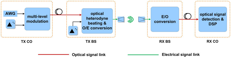
Figure 1 shows the principle of our optical wireless-fiber integration system[14]. The multi-level modulated wireless mm-wave signal is based on the heterodyning technique and is demodulated based on DSP[10]. The red solid lines show the optical signal links, and the green solid lines show the electrical signal links. At the central transmission office, a multi-level, modulated optical baseband signal is generated. After the multi-level, modulated optical signal is transmitted over a SMF-28 wire link, it is heterodyne-beaten with a continuous wavelength (CW) optical signal at the transmitter base station, and then detected by a PD to realize O/E conversion. Then, the multi-level, modulated radio mm-wave signal is delivered over a radio link with a pair of horn antennas (HAs) and a transmitter unit and receiver unit.
Sign up for Chinese Optics Letters TOC. Get the latest issue of Chinese Optics Letters delivered right to you!Sign up now

Figure 1.Principle of the wireless optical fiber integration system.
E/O conversion is accomplished at the receiver base station. Up until now, researchers have demonstrated techniques including intensity modulation with or without down-conversion[10,11], and phase modulation with or without down-conversion[12], to realize E/O conversion. Here, we use a DML, a low-cost scheme, to realize E/O conversion, and the 16QAM modulation format is used to increase spectrum efficiency. Here, the chirp from the DML is partly removed due to the adoption of the large DC bias[15]. At the receiver central office, we use direct detection with DSP to receive the multi-level modulated signal[16–22].
We compare the optical wireless link with or without the DML and the transmission fiber. First, we calculate the bit error ratio (BER) at different input powers into a 100 GHz PD without the DML and the transmission fiber. Then, we connect the DML and 2 km fiber in the receiver, and we calculate BER at different input powers in a 15 GHz PD. By comparing the two cases, we can investigate the performance of the wireless-fiber integration system with the DML as an E/O converter.
Figure 2 shows the experimental setup for the 10 Gb/s 16QAM signal transmission over the wireless-fiber integration link without the DML and the fiber. The two external cavity lasers (ECLs) have a linewidth smaller than 100 kHz. At the transmitter, the CW lightwave from ECL1 at 1558.47 nm is modulated by an in-phase/quadrature (I/Q) modulator, and then boosted by an erbium-doped fiber amplifier (EDFA). In order to generate the 16QAM modulated optical signal, two 2.5 Gbaud electrical four-level signals with samples and a word length of are generated by an arbitrary waveform generator (AWG) to drive the I/Q modulation. Before the I/Q modulation, two 2.5 Gbaud electrical four-level signals are pre-equalized to overcome the nonlinear characteristics of the two parallel Mach–Zehnder modulators in each I/Q modulator. Then, each electrical four-level signal is amplified by an electrical amplifier (EA) before driving the I/Q modulation[16,17]. In this experiment, EA1 and EA2 are linear amplifiers with a DC in the operating range, a gain of 30 dB, and an output power of 2 V. After generating the 16QAM modulated optical signal, ECL2 at 1559.79 nm is used as a local oscillator (LO), and the frequency difference between ECL1 and ECL2 is about 85.25 GHz. The LO has the same optical power as the received optical signal. A polarization-maintaining optical coupler (PM-OC) is used to couple the LO signal and the received optical signal. Figure 2(a) shows the optical spectrum (at a resolution of 0.01 nm) for a 2.5 Gbaud rate (10 Gb/s) 16QAM signal after the PM-OC. The total optical power is 12 dBm. A variable optical attenuator (ATT) is adopted to adjust the input power into a 100 GHz PD. The input power into the PD is . A single-ended PD, with a 100 GHz, 3 dB bandwidth, directly up-converts the optical 16QAM signal into an electrical 16QAM signal. The generated electrical signal is amplified by a W band EA, with 4 dBm saturation power, before being delivered to the air link. Figure 2(b) shows the gain curve of the W band amplifier; the gain is 22 dB at 85 GHz. The transmitter and receiver HAs have a 10 m wireless distance. Each HA has a 50.8 dBi gain and a 0.4° beam width.
Figure 2.Experimental setup for the 10 Gb/s 16QAM signal transmission over the wireless-fiber integration link without the DML or the fiber. (a) Optical spectrum (0.01 nm resolution) after PM-OC. (b) The gain curve of the W band amplifier.
Two-stage down conversion is implemented at the W band receiver. The received 85 GHz wireless mm-wave signal is first down-converted into a 10 GHz electrical intermediate-frequency (IF) signal in the analog domain in order to overcome the insufficient bandwidth of the subsequent electric devices[1,12]. A 12.5 GHz sinusoidal RF signal first passes through an active frequency doubler () and an EA in series. Next, the generated 25 GHz RF signal passes through a passive frequency tripler () and an EA. As a result of this cascaded frequency multiplication, an equivalent 75 GHz RF signal is provided for the balanced mixer, and a 10 GHz electrical IF signal is obtained after the analog down conversion. The conversion loss of the mixer is 7 dB. Then, a DC amplifier with a 35 dB gain and 22 dBm saturation power is employed to boost the 10 GHz electrical IF signal. The analog-to-digital conversion is realized in the digital storage oscilloscope (OSC) with a 50 GSa/s sampling rate and a 12 GHz electrical bandwidth. The baseband DSP is carried out after the analog-to-digital conversion by the OSC and includes timing recovery, IF down conversion[1,20], CD compensation, constant-multi-modulus-algorithm (CMMA) equalization, carrier recovery, differential decoding, and BER counting.
Figure 3 shows the BER versus the input power going into the PD for the 10 Gb/s 16QAM signal transmission without the DML or the fiber. The distance between the transmitter HA and the receiver antenna is 10 m. The required input power into the PD at a BER of is . Figure 3(a) shows the electrical signal spectrum before the digital storage OSC when the input power into the 100 GHz PD is . We can see that the IF is 10 GHz. The corresponding constellation after DSP is also shown in Fig. 3(b).
Figure 3.BER versus different powers being input into a 100 GHz PD. (a) Electrical signal spectrum before the digital storage OSC ( input power into a 100 GHz PD). (b) Constellation after DSP ( input power into a 100 GHz PD).
Figure 4 shows the experimental setup for the 10 Gb/s 16QAM signal transmission over the wireless-fiber integration link with the DML and a 2 km fiber in the receiver[23–25]. The transmitter and the HAs are the same as those in the above. At the receiver, we adopt the same scheme as in the first experiment to down convert the received 85 GHz 16QAM wireless mm-wave signal to a 10 GHz electrical IF signal. Then, two cascaded EAs (EA3 and EA4), each with a 40 GHz, 3 dB bandwidth, are used to boost the IF signal before it is used to drive a DML with a large DC bias of 86 mA, a RF peak-to-peak driving voltage of 3.1 V, and a bandwidth of 20 GHz. The model number of this DML is NLK1551SSC; it is from the NEL company. Figure 4(a) shows the DML power versus the DC bias. We can see that the DML works in a linear area when the DC bias is 86 mA and the corresponding output power is 8.2 dBm. Figure 4(b) shows the optical spectrum of the DML. We can see that the central wavelength is 1560.1 nm. The spectrum of the DML is not symmetrical due to the inherent residual chirp from the DML. Then, a variable optical attenuator (ATT2) is adopted to adjust the input power into a 2 km SMF-28, and an EDFA is cascaded to amplify the optical signal. The optical power after ATT2 is 0.7 dBm. Subsequently, a variable optical attenuator (ATT3) is adopted to adjust the input power into the PD with a 15 GHz bandwidth. The analog-to-digital conversion is realized in the digital storage OSC with a 50 GSa/s sampling rate and a 12 GHz electrical bandwidth. The baseband DSP is carried out after the analog-to-digital conversion by the OSC and includes timing recovery, IF down conversion[26,27], CD compensation, CMMA equalization, carrier recovery, differential decoding, and BER counting.
Figure 4.Experimental setup for the 10 Gb/s 16QAM signal transmission over the wireless-fiber integration link with the DML and 2 km fiber in the receiver. (a) DML power versus DC bias. (b) Optical spectrum of the DML.
Figure 5 shows the BER versus the input power into a 15 GHz PD for the 10 Gb/s 16QAM signal transmission with the DML. The distance between the transmitter HA and the receiver antenna is 10 m. Here, no fiber indicates that the optical signal is being transmitted back and forth from ATT2 to the EDFA. After 2 km, the fiber indicates that the optical signal is transmitted over a 2 km SMF-28. Compared to the case with no fiber, there is almost no input power into the 15 GHz PD for the case of the 2 km fiber. Figure 5(a) shows the electrical signal spectrum before the digital storage OSC when the input power into the 15 GHz PD is . According to the down-conversion structure, the IF should be 10.25 GHz. Instead; the IF in the electrical signal spectrum is around 9 GHz, due to the inherent residual chirp from the DML. The corresponding constellation after DSP is also shown in Fig. 5(b). The distortion of the 16QAM signal constellations is mainly caused by the saturation effect in the 100 GHz photodiode, the W band amplifier, and the DML.
Figure 5.BER versus input power into a 15 GHz PD for the 10 Gb/s 16QAM signal transmission with the DML. (a) Electrical signal spectrum before the digital storage OSC ( input power into a 15 GHz PD). (b) Constellation after DSP ( input power into a 15 GHz PD).
When the input power into the 15 GHz PD is , the BER is below , while the required input power into the PD at a BER of is for the case without the DML. The constellation of the DML scheme ( input power into a 15 GHz PD after the 2 km fiber) is as clear as the scheme without DML ( input power into a 100 GHz PD).
In conclusion, we demonstrate that a DML with a small size and low cost can be used to realize E/O conversion at wireless-fiber link. In this system, we demonstrate a 10 m wireless and a 2 km fiber connection. Our experimental results show that the DML is good device to be used for the E/O conversion of a 16QAM signal.
References
[1] J. Yu, X. Li, N. Chi. Opt. Express, 21, 22885(2013).
[2] C. H. Chang, P. C. Peng, H. H. Lu, C. L. Shih, H. W. Chen. Opt. Lett., 35, 4021(2010).
[3] S. Koenig, F. Boes, D. L. Diaz, J. Antes, R. Henneberger, R. M. Schmogrow, D. Hillerkuss, R. Palmer, T. Zwick, C. Koos, W. Freude, O. Ambacher, I. Kallfass, J. Leuthold. Proceedings of OFC 2013, PDP5B.4(2013).
[4] A. Kanno, K. Inagaki, I. Morohashi, T. Sakamoto, T. Kuri, I. Hosako, T. Kawanishi, Y. Yoshida, K. I. Ki-tayama. Proceedings of ECOC, We.10.P1.112(2011).
[5] C. W. Chow, F. M. Kuo, J. W. Shi, C. H. Yeh, Y. F. Wu, C. H. Wang, Y. T. Li, C. L. Pan. Opt. Express, 18, 473(2010).
[6] X. Pang, A. Caballero, A. Dogadaev, V. Arlunno, R. Borkowski, J. S. Pedersen, L. Deng, F. Karinou, F. Roubeau, D. Zibar, X. Yu, I. T. Monroy. Opt. Express, 19, 24944(2011).
[7] X. Li, J. Yu, N. Chi, J. Xiao. Opt. Lett., 39, 1169(2014).
[8] R. Sambaraju, D. Zibar, R. Alemany, A. Caballero, J. Herrera, I. T. Monroy. Proceedings of Optical Fiber Communication Conference 2010, OML1(2010).
[9] J. Yu, Z. Jia, L. Yi, Y. Su, G. K. Chang, T. Wang. Photon. Technol. Lett., 18, 265(2006).
[10] X. Li, J. Yu, N. Chi, J. Zhang. Opt. Lett., 38, 4712(2013).
[11] X. Li, J. Yu, J. Zhang, F. Li, Y. Xu, Z. Zhang, J. Xiao. IEEE Photon. Technol. Lett., 26, 1825(2014).
[12] X. Li, J. Yu, J. Xiao, Y. Xu. IEEE Photon. Technol. Lett., 26, 1948(2014).
[13] A. Yariv, P. Yeh. Photonics: Optical Electronics in Modern Communications(2006).
[14] J. Xiao, C. Tang, X. Li, J. Yu, X. Huang, C. Yang, N. Chi. Chin. Opt. Lett., 12, 050603(2014).
[15] D. Mahgerefteh, Y. Matsui, X. Zheng, K. McCallion. IEEE J. Sel. Top. Quant. Electron., 16, 1126(2010).
[16] J. Yu, X. Zhou. IEEE Commun. Mag., 48, S56(2010).
[17] Z. Dong, J. Yu, X. Li, G. K. Chang, Z. Cao. Proceedings of the Optical Fiber Communication Conference, OM3D.2(2013).
[18] J. Yu, X. Li, J. Zhang, J. Xiao. Proceedings of ECOC 2014, We.3.6.6(2014).
[19] D. Zibar, R. Sambaraju, A. Caballero, J. Herrera, U. Westergren, A. Walber, J. B. Jensen, J. Martí, I. T. Monroy. Photon. Technol. Lett., 23, 810(2011).
[20] J. Zhang, Z. Dong, J. Yu, N. Chi, L. Tao, X. Li, Y. Shao. Opt. Lett., 37, 4050(2012).
[21] S. J. Savory. IEEE J. Sel. Top. Quant. Electron., 16, 1164(2010).
[22] Z. Dong, X. Li, J. Yu, J. Yu. Opt. Express, 21, 1773(2013).
[23] Y. Xu, Z. Zhang, X. Li, J. Xiao, J. Yu. IEEE Commun. Lett., 18, 2105(2014).
[24] C. Tang, R. Li, Y. Shao, N. Chi, J. Yu, Z. Dong, G. K. Chang. Chin. Opt. Lett., 11, 020608(2013).
[25] J. Yu, X. Li, J. Yu, N. Chi. Chin. Opt. Lett., 11, 110606(2013).
[26] F. Li, Z. Cao, X. Li, Z. Dong, L. Chen. J. Lightwave Technol., 31, 2394(2013).
[27] X. Li, Z. Dong, J. Yu, N. Chi, Y. Shao, G. K. Chang. Opt. Lett., 37, 5106(2012).