
Jian Chen, Ling Fang, Qianwu Zhang, Junjie Zhang, Yingxiong Song, Yingchun Li, Min Wang. Experimental demonstration of 60 Gb/s optical OFDM transmissions at 1550 nm over 100 m OM1 MMF IMDD system with central launching[J]. Chinese Optics Letters, 2017, 15(6): 060603
- Chinese Optics Letters
- Vol. 15, Issue 6, 060603 (2017)
Abstract
Multi-mode fibers (MMFs) have been widely used in broadband local area networks (LANs) to provide cost-effective transmissions due to their large core diameters, which usually enable significant cost reduction in component manufacturing, installation, and maintenance[
In this Letter, record-high 60 Gb/s optical OFDM transmissions over IMDD-based 100 m OM1 MMF links are experimentally demonstrated, utilizing a 10 GHz electro-absorption modulated laser (EML) intensity modulators at a single 1550 nm wavelength. Adaptive subcarrier bit loading[
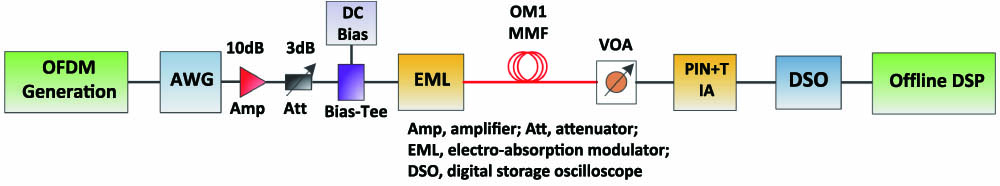
Our experimental setup is shown schematically in Fig.
Sign up for Chinese Optics Letters TOC. Get the latest issue of Chinese Optics Letters delivered right to you!Sign up now
| Parameter | Value |
|---|---|
| Modulation format | 64/32/16/4-QAM |
| IFFT/FFT size | 64 points |
| CP length | 16 points |
| Signal line rate | 60 Gb/s |
| OFDM symbols per frame | 100 symbols |
| MMF length | 100 m |
| MMF core size (fiber type) | 62.5 μm (OM1) |
| EML modulation bandwidth | 10 GHz |
| EML wavelength | 1550 nm |
| EML reverse DC bias voltage | |
| EML driving voltage | 1.23 Vpp |
| PIN detector bandwidth | 12 GHz |
| AWG sampling rate | 24 GS/s |
| DSO sampling rate | 80 GS/s |
| DSO/AWG resolution | 8 bit |
Table 1. Transceiver and System Parameters
![]()
Figure 1.Experimental setup for the 60 Gb/s OFDM MMF system.
At the receiver side, a 12 GHz PIN transimpedance amplifier (TIA) is utilized for O-E conversion by directly detecting the optical OFDM signal. And the received optical power (RoP) can be adjusted by a variable optical attenuator (VOA). The electric OFDM signal is then captured by a 25 GHz digital storage oscilloscope (DSO, Agilent DSO92504A) with an 8 bit analog-to-digital converter (ADC) operating at an 80 GS/s sampling rate. Signal demodulation can be realized by offline DSP procedures, which include symbol synchronization, CP removal, fast Fourier transforms (FFTs), channel estimation, QAM demodulation, and bit error counting. The transceiver parameters and operating conditions are fixed when the system performance measurements are made.
Adaptive subcarrier bits loading and online optimization of the EML operating conditions are applied for achieving maximum signal transmission capacity. At the first place of the bit loading procedure, the 64-QAM modulation format is assigned to all subcarriers, and then optimizations of transceiver parameters, including laser bias and modulation signal amplitude, are undertaken to push the total bit error rate (BER) lower than forward error correction (FEC) limit. If the total BER is still higher than the FEC limit after the mentioned optimizations, 1 bit is then decreased from the highest frequency subcarrier, according to the unequal bit error distribution caused by the system frequency roll-off. The abovementioned procedure can be repeated until the total BER meets the FEC requirement. The obtained optimum subcarrier bits allocation profile under a 100 m OM1 MMF with a central launching configuration is shown in Fig.
![]()
Figure 2.Adaptively loaded optimum subcarrier bit allocation profile for 60 Gb/s over a 100 m OM1 MMF.
Using the optimized adaptive loading parameters, the results in Fig.
![]()
Figure 3.BER performance of a 60 Gb/s OFDM signal at the OBTB, central launching, and offset launching condition over a 100 m OM1 MMF.
Compared to the central launching case, another 1 dB power penalty is introduced by using the 9 μm offset launching condition at the FEC threshold. Offset launching is usually adopted in MMF systems to avoid a central axial defect, which is mainly introduced during fiber manufacturing. In this case, the better performance of central launching can be contributed by (a) the employed adaptive loaded scheme, which is effective against fiber channel defects and (b) less intermodal dispersion impairment compared with the offset launching scheme. This indicates that the OM1 MMF can successfully support up to a 60 Gb/s signal line rate by using adaptive loaded optical OFDM signals with a simple central launching scheme without an additional mode conditioning patch cord, which gives a good potential solution to upgrading legacy MMF systems in data center interconnections. To our knowledge, this work is the highest capacity in MMF transmission systems with a directly modulated laser and direct detection.
To deeply understand the above behaviors of system performance, the frequency responses of systems from the input of EML in the transmitter to the output of the PIN detector in the receiver under the aforementioned three different configurations are experimentally measured via a vector network analyzer (VNA). It can be seen from Fig.
![]()
Figure 4.Frequency responses of OBTB, central launching, and offset launching condition over a 100 m OM1 MMF.
We can also find that the frequency roll-off of the offset launching case is more serious than the central launching case. Consider that the offset launching scheme inspires higher-order mode groups than the central launching scheme, which suffers a more serious intermodal dispersion impairment, so center launching scheme still can achieve a better performance even under the experience of slight deterioration due to the imperfect fiber structure. At this point, the MMF high-order mode dispersion becomes the dominant factor for influencing the performance on the current system configuration. This also explains the similar BER behaviors under the abovementioned three system configurations.
The received constellations of the representative subcarriers recorded after channel equalization are shown in Fig.
![]()
Figure 5.Constellations of (a) 12th subcarrier (SC), (b) 21st SC, (c) 25th SC, (d) 31st SC for the central launching system over a 100 m OM1 MMF.
In conclusion, record-high 60 Gb/s optical OFDM transmissions over IMDD-based 100 m OM1 MMF systems are experimentally demonstrated by using 10 GHz EML intensity modulators at a single 1550 nm wavelength. Adaptive subcarrier bit loading is also employed to combat the channel fading. Better system performance can be achieved by using simple central launching compared to the conventional offset launching.
References
[1] M. E. A. Diab, J. D. Ingham, R. V. Penty, I. H. White. J. Lightwave Technol., 25, 2976(2007).
[2] C. Kachris, I. Tomkos. Proceedings of OSA/OFC/NFOEC, JTh2A(2012).
[5] E. Giacoumidis, S. K. Ibrahim, J. Zhao, J. M. Tang, A. D. Ellis, I. Tomkos. IEEE Photon. Technol. Lett., 24, 52(2012).
[6] E. Hugues-Salas, Q. W. Zhang, R. P. Giddings, M. Wang. Future Network and Mobile Summit, 1(2013).
[8] L. Cheng, H. Wen, X. Zheng, H. Zhang, Y. Guo. Chin. Opt. Lett., 8, 377(2010).
[9] J. Shang, J. Chen, R. Lin, Y. Song, Y. Li. Chin. Opt. Lett., 11, S20607(2013).
[10] Z. Yin, G. Liu, F. Chen, B. Liu. Chin. Opt. Lett., 13, 071404(2015).
[11] R. Zhang, J. Li, Z. Huang, Y. Ji. Chin. Opt. Lett., 13, 072302(2015).
[12] J. Su, X. Li, J. Yu. Chin. Opt. Lett., 14, 050608(2016).
[13] X. Q. Jin, J. M. Tang. J. Opt. Network, 7, 198(2008).
[15] X. Gu, H. Chen, M. Chen, S. Xie. Chin. Opt. Lett., 10, 020601(2012).
[16] Y. G. Wang, Y. Q. Wang, N. Chi. Photon. Res., 2, 138(2014).
[17] C. C. Gui, J. Wang. Photon. Res., 4, 168(2016).
[19] J. W. Luo, J. P. Li, Q. Sui, Z. H. Li. Proceedings of ACP, AS4D(2015).
[20] J. Xu, C. Ruprecht, J. Von Hoyningen-Huene, W. Rosenkranz. Proceedings of OSA/OFC, OTh4A.2(2013).
[21] W. Z. Yan, T. Tanaka, B. Liu, M. Nishihara, L. Li, T. Takahara, Z. N. Tao, J. Rasmussen, T. Drenski. Proceedings of OFC/NFOEC, 1(2013).
[22] T. Tanaka, M. Nishihara, T. Takahara, W. Z. Yan, L. Li, Z. N. Tao, M. Matsuda, K. Takabayashi, J. Rasmussen. Proceedings of OSA/OFC, M2l.5(2014).
[23] Q. Yang, W. Shieh, Y. Ma. IEEE Photon. Technol. Lett., 20, 1305(2008).
[24] D. H. Sim, Y. Takushima, Y. C. Chung. J. Lightwave Technol., 27, 1018(2009).
[25] M. Webster, L. Raddatz, I. H. White, D. G. Cunningham. J. Lightwave Technol., 17, 1532(1999).

Set citation alerts for the article
Please enter your email address
© Copyright 2018-2021 | Chinese Laser Press. All Rights Reserved 沪ICP备15018463号-20