To obtain a laser output with a high-quality beam and a square, super-Gaussian, flat-top distribution, a high-energy laser needs to conduct spatial reshaping of the geometric outline of an injected Gaussian laser pulse and the non-uniform gain of multi-level energy amplification units. A digital micro-mirror device is very suitable for a working environment that has a high electromagnetic interference in a high-energy laser system. We present an algorithm and an experiment of spatial beam shaping that is based on the use of a digital micro-mirror device. Through secondary shaping, the near-field modulation degree of the beam (the ratio of the maximum value of the light intensity to the average value) decreases from ∶ (after primary shaping) to ∶, an improvement of 30.7%. The energy loss is 32.9%. Meanwhile, the beam after secondary shaping possesses extremely strong stability. Under the condition where the input-shaping aperture remains unchanged, the dispersity of the near-field modulation degree of the output beam is only 1.6%. Thus, the influences of the environmental changes and the random distribution of the “noise” in the beam intensity distribution are reduced.
To improve the fill factor of working material, increase the efficiency of the extraction of stored energy, and avoid the nonlinear “self-focusing” phenomenon that is caused by excessively strong partial light intensity damaging the optical components, the uniform distribution of the light intensity distribution in a high-energy laser is required. The ideal beam to achieve this uniform distribution is not a fundamental-mode Gaussian beam, but rather a super-Gaussian, flat-top, distributed beam. So, it is necessary to obtain a Gaussian beam shape from the geometric shape and the beam intensity distribution and to match them with the caliber of the working material. This suppresses the diffraction modulation and small-scale, high frequency spatial noise, and improves the near-field spatial distribution of the beam and output near the “flat-top, distributed” super-Gaussian beam with a high fill factor[1–3]. Because there are multi-level amplification units in a high-energy laser, the beam-shaping unit needs to have the ability to repair the beam distribution injected from the pre-amplifier unit, and also to pre-compensate for the non-uniform gain of the main amplifier unit. The spatial beam-shaping unit also needs to achieve a real-time feedback function, and to adjust the beam distribution in real time according to the changes in the output beam of the high-energy laser. This ensures that the output beam maintains a high uniformity and consistency for a long time.
A serrated-aperture apodizer provides a solution to change the edge distribution of the beam and avoid edge diffraction during the process of a Gaussian beam becoming a super-Gaussian, flat-topped beam[4]. However, it cannot change the intensity of the inhomogeneous distribution of the internal spot due to the non-uniform gain of the amplifiers in a high-energy laser system. Therefore, a device for the spatial beam shaping of a high-energy laser should be an active spatial light modulator in which each pixel point can be controlled through programming and can change flexibly according to the requirements and changes in the actual beam. Currently, the spatial light modulators that meet these requirements mainly include the liquid crystal spatial light modulator and the digital micro-mirror device. A liquid crystal spatial light modulator is an active and encodable spatial light modulator[5–7]. However, it has a shorter service life because it takes a long time to power on and the electrode becomes hot when loading under intense light. A liquid crystal spatial light modulator carries out analog modulation. A digital micro-mirror device is a kind of reflective, rapid digital optical switch composed of many small aluminum reflecting mirrors. Compared with the liquid crystal spatial light modulator, the digital micro-mirror device has the advantages of high reflectivity and a high damage threshold. In addition, a digital micro-mirror device carries out digital modulation, which has the advantages of a high-resolution ratio and an excellent anti-interference property when compared to the analog modulation of the liquid crystal spatial light modulator[8]. Thus, it is quite suitable for the working environment of a high-energy laser, which has a strong electromagnetic interference. Although, beam shapers based on the liquid crystal spatial light modulator and the digital micro-mirror device have been demonstrated in laser systems[9–11], particularly in high-energy laser systems, in this Letter, the beam only passes through the beam shaper and then reaches the image plane by an image lens. Because of the lack of energy amplifiers in these experimental setups, they do not demonstrate the function of eliminating the inhomogeneous intensity distribution of the internal spot due to the non-uniform gain of amplifiers, and the beam shapers simply play a similar role to that of a serrated-aperture apodizer.
In this Letter, we study spatial shaping technology based on the digital micro-mirror device in a high-energy laser system with a multi-level energy amplification unit. Spatial beam shaping is conducted twice, using the digital micro-mirror device. Not only does the edge distribution of the beam change, but also the inhomogeneous intensity distribution of the internal spot from the pre-amplifier unit and main-amplifier unit is repaired. Additionally, a super-Gaussian, flat-top, distributed laser output with high beam quality and high caliber () is achieved.
Sign up for Chinese Optics Letters TOC. Get the latest issue of Chinese Optics Letters delivered right to you!Sign up now
A digital micro-mirror device is a reflective, rapid digital optical switch integrated on an addressing integrated chip, and is composed of many small aluminum reflecting mirrors. The quantity of mirrors depends on the display resolution. A small mirror corresponds to a pixel. A pair of addressing electrodes is below each micro-mirror unit. The addressing electrode is connected through an electric channel to a complementary end of a complementary metal oxide semiconductor (CMOS) circuit of a static random access memory (SRAM) unit. The SRAM unit is used to address each micro-mirror. By changing the address voltage of each micro-mirror under the CMOS, an electrostatic force can be generated to drive a micro-mirror to turn over along the diagonal axis backwards and forward. When the light is incident on the digital micro-mirror device, the positive and negative working modes of the micro-mirrors reflect the incident light at different angles. By adjusting the angle of the incident light, the micro-mirrors in the two working modes systematically correspond to dark and bright pixels so that the light being projected to the digital micro-mirror device can reflect selectively to form black and white pixels, i.e., “off” and “on” states. Thus, the digital micro-mirror device can be designed to be a reflective spatial light modulator whose pixel level can be controlled through programming to work on the spatial shaping of the beam. The reallocation of the incident spot transmittance is managed by depending on the programmable control of the spatial distribution of the “black” and “white” pixels in the aperture in the digital micro-mirror device.
A high-energy laser possesses multi-level amplification units and numerous various components. The changes in the structure and temperature caused by environmental vibration, airflow, and pressure flow will influence the stability of the system, thus causing the output of the laser intensity distribution to change with time. Meanwhile, the image input, collection, and processing will introduce random “noise.” This will also cause changes in the output of the laser intensity distribution with time after the feedback to the spatial beam shaping process. If an error diffusion algorithm is introduced into the shaping algorithm, the error diffusion process will effectively reduce the error resulting from the nonlinear system so that the intensity distribution is no longer sensitive to environmental changes and random “noise” distribution[12,13]. In this Letter, we modify the error diffusion algorithm and adopt a self-adaptation partitioning threshold value method in the threshold value selection. In other words, each sub-block has an independent threshold value, instead of using a single threshold value for the whole image. We choose an average value as the threshold value.
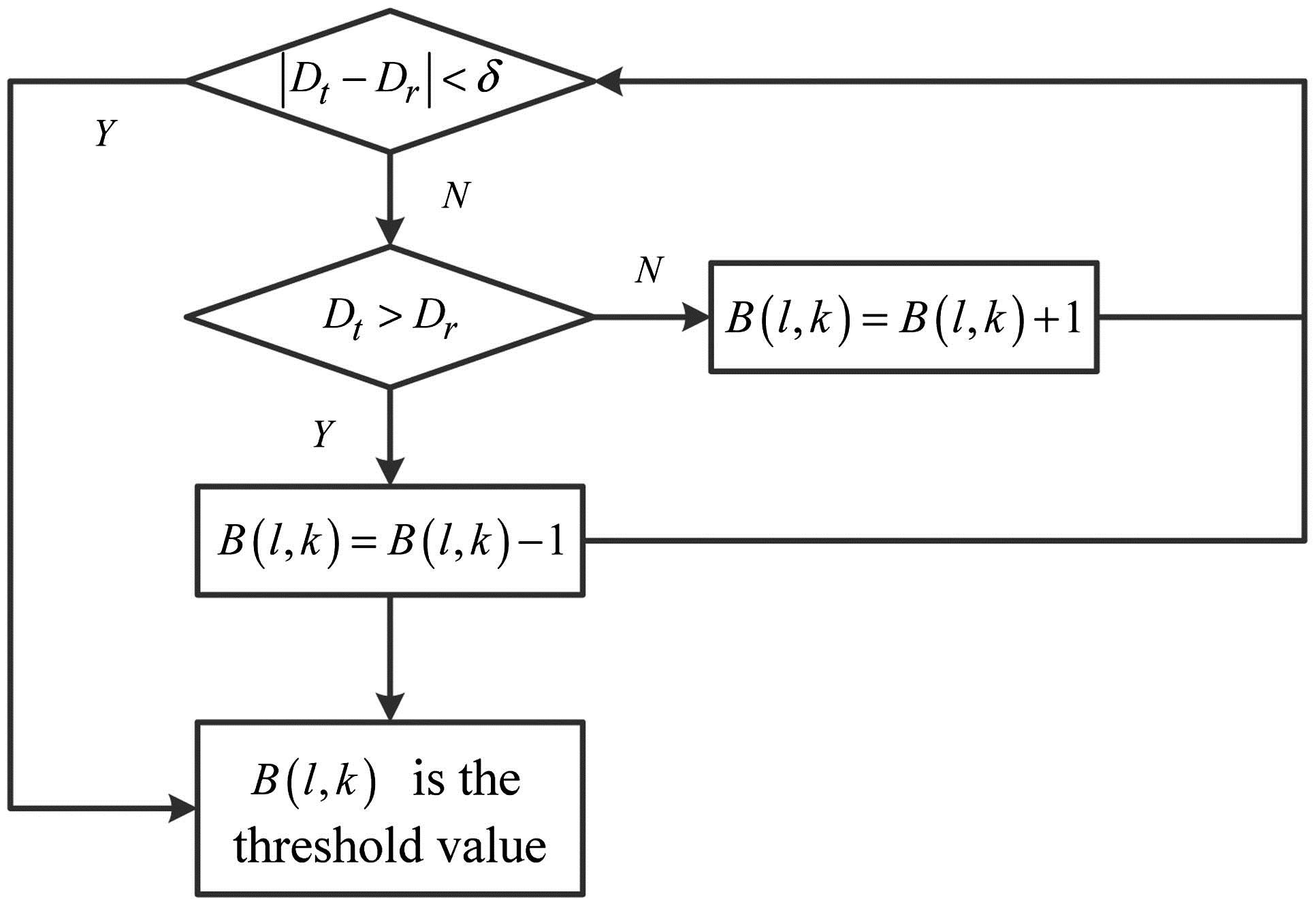
Prior to error diffusion, we first divide the original image into several sub-blocks with the pixel size of y × y, and solve for the average gray value of each sub-block. The computational formula is as follows: where is the gray value of the pixel point in the th line and th row. and are decided by the image size and . We count the number and of the pixels in the sub-blocks with a gray value more than and less than , respectively. We calculate the threshold value of according to the flow chart shown in Fig. 1. Different values will be found for the different sub-blocks. Then, the Floyd–Steinberg error diffusion process [as shown in Fig. 2(b)] is adopted for a binary calculation of the image. The target image is expressed as . The error is . We then diffuse it towards the adjacent four directions according to the proportion of ∶∶∶. The adjacent four pixels gain 7/16, 3/16, 5/16, and 1/16 of the error, respectively, i.e.:
Then, we compare these points with the threshold value and conduct binarization and the next process according to the flow shown in Fig. 3. The function takes for its value , , , and .
Figure 1.Flow chart for the threshold value calculation.
The schematic diagram of the experimental setup is shown in Fig. 4. In the experiments, a Nd:phosphate glass is used as the laser’s working substance. A multi-level, double-pass amplification of the laser diode (LD) side-pumped Nd:glass rod with a small diameter of 2 mm is used for the preamplifier unit. A LD end-pumped flake Nd:glass with a large caliber of 30 mm and multi-pass amplification is used for the main amplifier unit. A linearly polarized Gaussian laser pulse with the energy of 1 nJ, a wavelength of 1053 nm, a pulse width of 3 ns, and beam caliber of is injected into the preamplifier unit to amplify the energy to 20 mJ. Then it enters a beam expander group composed of L1 and L2 to expand the spot to from there, it enters the digital micro-mirror device. Because of the positive and negative working modes of the micro-mirrors, they reflect incident light at different angles. When black pixels are written on the digital micro-mirror device, the reflected light is transmitted in the direction of the light absorber. Conversely, when white pixels are written on the digital micro-mirror device, the reflected light is transmitted in the direction of the main amplifier unit. After the reflection by the digital micro-mirror device, the beam presents a square, Gaussian, flat-top, distributed spot with a beam caliber of and an energy of 2.75 mJ. After expanding the beam to , the main amplifier unit amplifies the energy to 100 mJ and then outputs the energy. A scientific CCD is used to measure the spatial beam distribution on the image plane of the laser output spot. At the same time, a drive and control unit is adopted to control the scientific CCD and the digital micro-mirror device to realize the real-time online feedback function.
The preamplifier unit of a high-energy laser is used to amplify the energy of the round Gaussian distribution beam. In order to gain a super-Gaussian, flat-top, distributed laser output, it is necessary to shape the geometrical shape and outline distribution of the laser beam. We use the digital micro-mirror device to write the initial square spot. This shapes the approaching round Gaussian distribution beam into a square Gaussian, flat top, distributed beam.
For this work, a Texas Instruments digital light processing, binary-amplitude spatial light modulator based on the digital micro-mirror device is used. It has a wide range of wavelengths from 350 to 2700 nm. The array size of the digital micro-mirror device used is . The micro-mirror size is μμ, and the size of the micro-mirror screen is . A schematic diagram of each beam caliber is shown in Fig. 5. To eliminate the internal diffraction modulation of the square spot, the following two questions need consideration. On the one hand, the four right angles of the square spot will lead to closed-angle diffraction. Thus, it is necessary to carry out fillet processing for the right angles of the square spot. The definition of fillet is: . To have the duty ratio of the spot as large as possible and eliminate the closed-angle diffraction effect, the size of the fillet is set to 0.15. On the other hand, in a bid to eliminate the modulation phenomenon resulting from the hard-edge spot, it is necessary to soften the spot edge. The softening factor is defined as the ratio of the geometric distance of the beam intensity between the full-intensity caliber and zero-intensity caliber to the zero-intensity caliber, i.e., (as shown in Fig. 6). To improve the fill factor of the beam and restrain the diffraction effect as far as possible, the softening factor is set to 10%. So, in line with the error diffusion algorithm based on the self-adaptive partitioning threshold value method, the initial spot is written onto the digital micro-mirror device, as shown in Fig. 7. The beam in the laser takes the digital micro-mirror device as the object plane to conduct a conformal transmission to create the “image transfer” relationship.
Figure 5.Schematic diagram of the beam caliber in the digital micro-mirror device.
When writing on the primary shaping aperture in the digital micro-mirror device as shown in Fig. 7, a two-dimensional distribution and three-dimensional distribution of the spot, and a one-dimensional distribution of its specific position are collected on the surface at the outlet of the laser, as shown in Fig. 8. Since the primary shaping light shapes the geometrical shape and outline distribution of the spot, it has no ability to repair the beam injected by the preamplifier unit and thus to pre-compensate for the non-uniform gain of the main amplifier unit. As can be seen from the morphology of the output spot, the beam uniformity is poor, the intensity distribution fluctuates greatly, and the outline of the spot does not show flat-topped distribution. In a word, to realize beam output with a high beam quality and flat-topped distribution, secondary shaping, which is another step of the program, is required to improve the uniformity of the spot intensity.
Figure 8.(a) Two-dimensional distribution of the output spot. (b) Three-dimensional distribution of the output spot. (c) One-dimensional distribution of the pixel after primary shaping.
A near-field modulation degree is used to measure the uniformity of the output beam. The near-field modulation degree is defined as the ratio of the peak intensity to the mean intensity in a full-intensity caliber distributed in a laser pulse space. It is one of key indices to measure the beam quality of a high-energy laser. The mathematical expression is as follows: where is the peak intensity of the spatial beam distribution and is the average intensity of the spatial beam distribution. This mathematical expression is used to calculate the spot shown in Fig. 8. The near-field modulation degree is ∶. However, in a high-energy laser with a high beam quality, the near-field modulation degree of a super-Gaussian, flat-top, distributed beam that is required is less than ∶.
In accordance with the above algorithm, we calculate the secondary shaping aperture written on the digital micro-mirror device, as shown in Fig. 9. We find by comparing it to Fig. 8(a) that this figure is exactly complementary with it in terms of the intensity distribution. After secondary spatial beam shaping, the two-dimensional distribution and three-dimensional distribution of the spot, and the one-dimensional distribution of the specific position collected on the surface at the outlet of the laser are shown in Fig. 10. It can be seen from the figure that the uniformity of the spot intensity has greatly improved. At this moment, the near-field modulation degree of the spot is ∶, an improvement of 30.7% when compared to the primary spatial beam shaping.
Figure 9.Secondary shaping aperture written in the digital micro-mirror device.
Figure 10.(a) Two-dimensional distribution of the output spot. (b) Three-dimensional distribution of the output spot. (c) One-dimensional distribution of the pixel after secondary shaping.
The energy of the round Gaussian beam with a diameter of φ before entering the digital micro-mirror device is 20 mJ. When writing the primary shaping aperture with a fillet of 0.15, a softening factor of 0.1, and the caliber of onto the digital micro-mirror device, the energy of the digital micro-mirror device is 4.1 mJ. There is a 79.5% energy loss from the interception of the square spot by the round spot; another energy loss is derived from the diffraction effect of the reflector array with a net-shaped arrangement. When writing the secondary shaping aperture (as shown in Fig. 9) onto the digital micro-mirror device, the energy of the digital micro-mirror device is 2.75 mJ. There is a 32.9% energy loss introduced again. This part of the energy loss comes from the reassignment of the beam intensity, which is aimed at the non-uniform gain of the preamplifier and main amplifier units.
The dispersity of the near-field modulation degree of the output beam is used to measure the stability of the beam intensity distribution after shaping. When writing the secondary shaping aperture as shown in Fig. 9 onto the digital micro-mirror device, we collect the laser output 20 consecutive times. The scatter diagram of the near-field modulation degree of each time is shown in Fig. 11. The dispersity of the near-field modulation degree of the beam is 1.6%. This indicates that the near-field modulation degree of the output beam has excellent stability.
Figure 11.Near-field modulation degree distribution of 20 output beams.
In conclusion, we study the algorithm and perform an experiment on spatial beam shaping in a high-energy laser. We show the ability of spatial beam shaping to repair the beam intensity distribution injected from the preamplifier unit, and to pre-compensate for the non-uniform gain of the main amplifier unit by means of an improved error diffusion algorithm and a digital micro-mirror device. Through secondary shaping, the intensity uniformity of a square output laser improves significantly. The near-field modulation degree is reduced from ∶ after primary shaping to ∶, an improvement of 30.7%. The energy loss introduced is 32.9%. Under the circumstance where the secondary shaping aperture written onto the digital micro-mirror device remains unchanged, the dispersity of the near-field modulation degree of output beam is just 1.6%. This indicates very strong shaping stability.