Abstract
Transition radiation (TR) induced by electron–matter interaction usually demands vast accelerating voltages, and the radiation angle cannot be controlled. Here we present a mechanism of direction controllable inverse transition radiation (DCITR) in a graphene-dielectric stack excited by low-velocity electrons. The revealed mechanism shows that the induced hyperbolic-like spatial dispersion and the superposition of the individual bulk graphene plasmons (GPs) modes make the fields, which are supposed to be confined on the surface, radiate in the stack along a special radiation angle normal to the Poynting vector. By adjusting the chemical potential of the graphene sheets, the radiation angle can be controlled. And owing to the excitation of bulk GPs, only hundreds of volts for the accelerating voltage are required and the field intensity is dramatically enhanced compared with that of the normal TR. Furthermore, the presented mechanism can also be applied to the hyperbolic stack based on semiconductors in the infrared region as well as noble metals in the visible and ultraviolet region. Accordingly, the presented mechanism of DCITR is of great significance in particle detection, radiation emission, and so on.1. INTRODUCTION
Electron–matter interaction, which has been studied for a long time [1–14], is of great significance in many fields, such as particle detection [15,16], radiation emission [17–20], and scanning electron microscopes [21–24]. It is known that radiation emits when electrons traverse the interface of the different mediums due to the mismatch of the boundary conditions, corresponding to transition radiation (TR) [1,2], which distributes in a wide angular range. While the electrons move faster than the light velocity in the medium, the accompanying fields of the moving electrons are thrown away to radiate in the medium in a cone determined by both the electron velocity and the medium permittivity, known as Cherenkov radiation (CR) [4,5]. According to these mechanisms, both the TR and CR require a vast accelerating voltage to get relativistic electrons, and the radiation angle is difficult to be controlled, which limits the further development of the amplification of electron–matter interaction.
The progress of artificial materials paves a promising route to explore novel phenomena of the conventional electron–matter interaction to address these problems [25–29]. It is reported that the threshold-free inverse CR is found in hyperbolic metamaterials (HMMs) consisting of periodically arranged Au and dielectric layers [26], as well as angle-controllable CR by resonance TR in designed photonic crystals [27]. Besides, the inverse Doppler and Smith–Purcell effects [28,29] have also been presented by employing kinds of metamaterials.
Among these kinds of artificial materials, HMMs exhibit electromagnetic features unattainable in conventional mediums due to the unique hyperbolic iso-frequency dispersion induced by the coupling of propagating or localized surface plasmons (SPs) [30–34]. The coupling enables the propagation of evanescent waves and enhances the field, for which HMMs have attracted great interest in nanophotonics and light emissions, for instance, in hyperlenses [35] and enhanced spontaneous and thermal emissions [36,37]. Due to the excellent electronic properties, graphene, a two-dimensional honeycomb of carbon atoms, has attracted great interest in modern science and technologies such as nonlinear photonics, absorbers for ultrafast pulsed lasers, broadband polarizers, and optical cavities [38–41]. And owing to the SPs’ sustainability induced by the dynamic conductivity and tunability resulting from the bias voltage gating, the graphene sheet is also considered a promising candidate for HMMs in the terahertz region [42,43]. For a monolayer graphene sheet, it is reported that swift electrons excite both TR and graphene plasmons (GPs) on the surface [44–46], and a conventional TR distributed in a wide angular range based on graphene HMMs excited by swift electrons was also presented [47].
Sign up for Photonics Research TOC. Get the latest issue of Photonics Research delivered right to you!Sign up now
Here we present a mechanism of direction controllable inverse transition radiation (DCITR) based on the interaction between low-velocity electrons and graphene HMMs by a rigorous method of transfer matrix and GP excitation. The mechanism reveals that the DCITR originates from a spatial dispersion depending on wavevectors induced by the GP coupling and the superposition of the individual coupled bulk GP modes in graphene HMMs. Thus, distinct from the conventional TR, the DCITR propagates along a special inversed radiation angle, which is normal to the Poynting vector and can be controlled by adjusting the chemical potential of the graphene sheets. Further, due to the excitation of the GPs, only hundreds of volts for the accelerating voltage are required and the field of DCITR is greatly enhanced in the HMMs.
2. MECHANISM AND METHODS
When electrons traverse the interface between two different mediums, the waves accompanied with the moving electrons cannot satisfy the boundary conditions, which results in the excitation of additional fields, including the TR propagating outward from the incident spot, and the evanescent waves attenuating rapidly on the interface [1,2]. For an interface loaded with a doped graphene sheet, the additional evanescent waves could also excite the GPs further, causing them to propagate and become strongly confined on the interface [24].
For the stacked graphene consisting of periodically arranged alternative graphene sheets and dielectric buffers shown in Fig. 1, there are more distinctive characteristics of the GPs in the stack due to the strong coupling between the adjacent graphene sheets. On the one hand, a number of GP modes are excited, which indicates a much more complex frequency dispersion induced by the coupling. On the other hand, the strong coupling makes the GPs become bulk modes, which introduces a spatial dispersion for the stack depending on the wavevector. Thus, the superposition of the bulk modes and the induced spatial dispersion give rise to a DCITR.
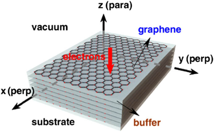
Figure 1.Schematic of the stacked graphene. The free electrons traverse the stack, which consists of periodically arranged alternative graphene sheets and dielectric buffer with permittivity and thickness , along the (parallel to the electrons) direction. The excited GPs propagate along the and (perpendicular to the electrons) directions.
To analyze the DCITR, the stack with layers of graphene sheets is divided into regions for the different buffers. The free electrons traverse normally to the surface of the stack along the direction. Because of the low velocity of the electrons, we only consider the electrons traversing the first graphene sheet with a constant velocity and charge quality . The conductivity of graphene sheet is [44,45], and the thickness and permittivity of the dielectric buffer are and , respectively. Then the fields accompanied by the moving electrons are expressed as [48] where the subscript denotes the incident region or the first buffer region, denotes the perpendicular direction (the and directions), and is the wavevector in a vacuum.
By employing the additional fields, including the TR and GP fields, the boundary conditions on the first graphene sheet are expressed by the continuity of the fields as where the superscript denotes the additional fields. In the stack, the fields in the first buffer region are coupled with those in the adjacent regions, which can be obtained by a transfer matrix as where the matrices and are the propagating and boundary transfer matrices in region , respectively, and where is the wavevector along the direction in region , , and is the wave impedance in a vacuum.
Solving Eq. (3), the coupled fields in region 1 are modified by factors and , corresponding to the waves propagating along the positive and negative direction, respectively. Then the additional fields in the substrate are given by Eq. (2) through an integral in wavevector domain [24,47,48] as where and .
It is found that Eq. (5) represents a propagating wave when is smaller than , corresponding to the conventional TR. For the case of being larger than , the denominator of Eq. (5) is just the frequency dispersion relation of the coupled GPs in the stack, indicating the excitation of the GPs when it reaches zero value at the plasmon poles. The GPs confined in the stack’s energies are much stronger than those of TR. Accordingly, the excited GPs could be obtained by the pole approximation of plasmons and the Taylor expansion [24]. We mark the wavevectors at the poles as , and then the DCITR fields are expressed by the superposition of the modes as [24,48] where is the distance between the electrons spot and observation points, is the molecule, and is the derivatives of the denominator of Eq. (5), respectively. Then all the fields in the stack can be obtained by the transfer matrix as shown in Eq. (3). For the excitation of GPs, only TM modes are considered in this paper.
3. RESULTS
Based on the presented mechanism, to study the features of DCITR, the frequency dispersion and excitation probabilities of GPs in the stack are studied first. Assuming a stack consisting of 10 layers of the graphene sheet, the dispersion curves for 10 individual modes are demonstrated in Fig. 2(a). Due to the multi-boundary in the stack, there could be two fundamental GP modes corresponding to the vacuum/buffer and buffer/buffer interfaces shown as the green dashed lines in Fig. 2(a). It is found that the dispersion curves deviate around the fundamental modes, since all 10 individual modes originate from the modification of the fundamental modes induced by the coupling between the adjacent graphene sheets. In the strong coupling region, because of the rising difference between the two wavevectors of the fundamental modes, these dispersion curves are distributed in an increasingly wide region with the increase of frequency. As shown in Fig. 2(b), the plasmon poles for 15 THz are more widely distributed than those for 12 THz. With the further increase of frequency, the coupling is reduced due to the decrease of the penetration depth of each GP mode on the interfaces. Accordingly, it can be seen in Fig. 2(a) that most of the deviated dispersion lines are again gradually approaching the fundamental modes at high frequencies. As shown in Fig. 2(b), the poles for 17 THz present a narrower distribution than for 15 THz; for 22 THz, the poles would almost be concentrated at the fundamental modes.

Figure 2.Dispersion curves of the stack and the poles distribution. (a) The frequency dispersion curves with normalized excitation probabilities in the logarithmic scale; is 100 nm, and are 2.1, and the chemical potential of the graphene sheets is 0.15 eV. There appear 10 curves around two fundamental modes for the stack with 10 layers of graphene sheets, induced by the GP coupling. (b) The GP pole distributions at 12, 15, and 17 THz.
The normalized excitation probabilities, defined by according to Eq. (6), are drawn as the gradually changing color in Fig. 2(a), which shows that the GP modes could be excited efficiently at the poles with low group velocities. Thus, it is found that the amplitudes of the modes reach the maximum values around 15 THz and drop sharply with the increase or decrease of the frequency. The detailed excitation probabilities are shown in Fig. 2(b) at the fixed frequencies 12, 15, and 17 THz. It is demonstrated that most of the GP modes are excited efficiently in the strong coupling region, like those at 12, 15, and 17 THz. For 22 THz, only the modes contiguous to the fundamental modes are excited.
To confirm the details of the presented mechanism of the DCITR, the contour maps of the individual bulk GP modes are also studied at a fixed frequency, which is chosen to be 12 THz for a more obvious DCITR at this frequency component. As shown in Fig. 3(a), the contour map of the fourth mode at 12 THz demonstrates that the fields propagate along the ( and ) direction, and they distribute along the direction as a standing wave, shaping a -like bulk mode in the stack. From a detailed viewpoint, it can be found that the amplitude reaches the maximum on the interfaces of the graphene sheets, indicating that the GPs, which are supposed to be confined on the interfaces, are coupled into a bulk mode by the field interactions between the adjacent graphene sheets. Accordingly, the GP fields can be considered as a propagating wave with a wavevector larger than along the direction determined by the plasmon poles and an effective one along the direction induced by the coupling, which strongly indicates a hyperbolic-like dispersion of the stack. For a higher-order mode, like the tenth mode shown in Fig. 3(b), the fields are mainly distributed on the top several graphene sheets and attenuate rapidly along the direction. This is induced by the weak coupling due to the raising plasmon poles, which results in a shorter penetration depth for the high-order mode and makes the stack present a plasmonic-like dispersion. Therefore, due to the GP coupling, the graphene stack presents a spatial dispersion depending on the wavevector, which is the physics of the DCITR.
Figure 3.Contour maps of the electric field along the direction for individual modes. (a) The contour map and field amplitude profile of the 4th mode at 12 THz, in which a -like mode is formed by the coupling, indicating a hyperbolic-like spatial dispersion. (b) The contour map and field amplitude profile of the 10th mode at 12 THz, in which the fields are mainly confined on the upper surface, indicating a plasmonic-like spatial dispersion.
Next we move on to the synthesized fields of these individual bulk GP modes at 12 THz. As demonstrated in Fig. 4(a), the overlying modes make the fields appear to have unique characteristics that are distinct from the conventional TR or GPs on a monolayer graphene sheet, as shown in Figs. 4(b) and 4(c).
Figure 4.DCITR from the individual bulk GP modes. (a) The contour map of the electric field along the direction of DCITR at 12 THz, in which the field propagates along an radiation angle normal to the Poynting vector. The inset is that at 22 THz, which is confined on the first several graphene sheets. (b) The contour map of the TR in normal medium at 12 THz. (c) The electric field contour map of the GPs on the monolayer graphene sheet at 12 THz; (d) and (e) the normalized field intensity via the number of graphene sheet, in which the field intensity of DCITR attenuates in the form of an inverse proportional function of the graphene sheet number.
First, parts of the fields are confined around the first several graphene sheets to form the GP-like fields, which are induced by the superposition of the high-order GP modes at large wavevectors with plasmonic-like spatial dispersion. The others are leaked from the upper surface into the graphene stack in a special upwards radiation angle and reflect in the stack to form interference spots corresponding to the propagating-like fields. This is because the hyperbolic-like spatial dispersions of low-order GP modes with small wavevectors enable the GP modes, which are supposed to be confined on the graphene surface, to propagate in the stack. Meanwhile, the composition of these low-order GP modes also makes the propagating fields appear at a unique radiation angle further, which is determined by the plasmon pole distribution of these modes. This is confirmed further by the contour at 22 THz in the stack. It is found in the inset of Fig. 4(a) that the fields are all confined on the surface of the stack, resulting from the plasmonic-like spatial dispersion at a large wavevector due to weak GP coupling.
Second, further calculation shows that the Poynting vector of the GP-like fields lies in the direction, but that of the propagating-like fields is in the direction of (normal to the direction of propagation), which greatly distinguishes it from those of conventional TR or individual GP modes as shown in Figs. 4(b) and 4(c). Furthermore, the dependence of the field intensity on the number of graphene sheets presented in Fig. 4(d) also indicates that the fields probed on the last graphene sheet decrease in the form of an inverse proportional function of the graphene sheet number, which is consistent with the radiation feature. But the fields for a monolayer graphene sheet attenuate exponentially with distance as shown in Fig. 4(e). Accordingly, the DCITR, resulting from the hyperbolic-like spatial dispersion and overlying of the coupled bulk GP modes, is realized.
Based on the mechanism presented above, it can be concluded that the radiation angle and field intensity of DCITR strongly depend on the pole distribution and mode excitation. The dependences of the radiation angle and field intensity on the frequency probed on the lower surface are shown in Fig. 5(a). The stack is chosen to be 30 layers to exclude the GP-like part from fields for the attenuation features of the GP-like and DCITR fields. For a more concentrated pole distribution, the DCITR would be closer to the GPs, which induces a larger radiation angle, until it propagates along the direction. As the red line shows in Fig. 5(a), the radiation angle decreases with the rising frequency until 15 THz, and then it increases, which is in accordance with the frequency dispersion given in Fig. 2(a). For the field intensity, the maximum is also obtained around 15 THz as the solid blue line shows in Fig. 5(a), which is induced by the largest excitation probability given in Fig. 2(a).
Figure 5.Radiation angle and normalized field intensities. (a) The dependences of the field intensities and radiation angle on the frequencies. (b) The dependences of the field intensities on the electrons velocities at 12 and 15 THz, respectively. (c) The dependence of the field intensity on the chemical potential of the graphene sheets. (d) The dependence of the radiation angle on chemical potentials of the graphene sheets.
Further, due to the excitation of GPs and propagation of the DCITR, the field intensity is greatly enhanced by about 10 orders of magnitude compared with that of conventional TR or GPs on a monolayer graphene sheet as shown in Fig. 5(a). Therefore, the field intensity of the DCITR can be optimized by adjusting the velocity of these traversing electrons. As shown in Fig. 5(b), the fields reach the maximum for the relatively slow electrons corresponding to an accelerating voltage of about 150 V, which are much smaller than those of conventional TR or CR and are in accordance with those of GPs excited by perpendicular moving electrons [44–46].
The pole distributions and excitation probabilities are strongly determined by the coupling of the graphene sheets, which depends on the penetration depths of the GP modes on the individual graphene sheets, and the features of the DCITR can be controlled by adjusting the chemical potentials as well as the thickness and dielectric permittivity of the dielectric buffer. For instance, the rising chemical potential shifts the GP dispersion into a higher frequency region, and then the poles of the fixed frequency are shifted from the weak coupling region into the strong region. Thus, both the excitation probabilities and the range of the pole distribution increase first and then decrease, which indicates thresholds of chemical potential for both the field intensity and radiation angle of the DCITR. As shown in Fig. 5(c), the fields of DCITR at 12 THz reach the maximum at 0.112 eV. Meanwhile, the increasing GP pole distribution range leads to an increasing radiation angle, and a decreasing range induces a decreasing angle. Accordingly, the radiation angle at 12 THz is deduced from 67° to 38.7° by adjusting the chemical potential from 0.05 to 0.1 eV and is raised from 38.7° to 64.6° for the chemical potential ranging from 0.1 to 0.3 eV as shown in Fig. 5(d).
4. SUMMARY
In summary, the mechanism of DCITR in the graphene stack excited by low-velocity electrons is presented. The detailed analyses show that the DCITR originates from the hyperbolic-like spatial dispersion induced by the GP coupling between the adjacent graphene sheets, and the excited bulk GP mode superposition makes the DCITR propagate along an inverse radiation angle normal to the Poynting vector. Therefore, the features of the DCITR strongly depend on the plasmon poles’ distribution and excitation probabilities. Thus, the radiation angle of DCITR can be controlled by adjusting the chemical potential as well as the design of the stack. Further, owing to the excitation of the GP modes, only hundreds of volts for the accelerating voltage are required for the traversing electrons, which is much lower than that of the relativistic electrons used in conventional TR or CR. The field intensities of DCITR are also dramatically enhanced by the excited GP modes.
On the other hand, the mechanism revealed here by rigorous electromagnetic theory also shows how the evanescent waves in a normal medium are transformed into radiation fields in HMMs. Thus, the mechanism can also be applied to HMMs based on the stacked semiconductors in the infrared region as well as stacked noble metals in the visible and ultraviolet region. Even a DCITR in non-periodical stacked plasmonic materials can be analyzed by this mechanism, for instance, the non-periodical graphene chemical potential or dielectric buffer. Accordingly, the presented mechanism of DCITR is of great significance in particle detection, radiation emission, and so on.
References
[1] F. G. Bass, V. M. Yakovenko. Theory of radiation from a charge passing through an electrically inhomogeneous medium. Sov. Phys. Usp., 8, 420(1965).
[2] V. L. Ginzburg. Transition radiation and transition scattering. Phys. Scripta, T2A, 182-191(1982).
[3] I. Frank, I. Tamm. Coherent visible radiation from fast electrons passing through matter. C.R. Acad. Sci. USSR, 14, 109-114(1937).
[4] P. A. Cherenkov. Visible emission of clean liquids by action of γ radiation. Doklady Akademii Nauk SSSR, 2, 451(1934).
[5] W. Galbraith, J. V. Jelley. Light pulses from the night sky associated with cosmic rays. Nature, 171, 349-350(1953).
[6] C. J. Hirschmugl, M. Sagurton, G. P. Williams. Multiparticle coherence calculations for synchrotron-radiation emission. Phys. Rev. A, 44, 1316-1320(1991).
[7] G. L. Orlandi. Coherence effects in the transition radiation spectrum and practical consequences. Opt. Commun., 211, 109-119(2002).
[8] A. Yurtsever, M. Couillard, D. A. Muller. Formation of guided Cherenkov radiation in silicon-based nanocomposites. Phys. Rev. Lett., 100, 217402(2008).
[9] C. Kremers, D. N. Chigrin, J. Kroha. Theory of Cherenkov radiation in periodic dielectric media: emission spectrum. Phys. Rev. A, 79, 013829(2009).
[10] O. Lundh, J. Lim, C. Rechatin, L. Ammoura, A. Ben-Ismail, X. Davoine, G. Gallot, J.-P. Goddet, E. Lefebvre, V. Malka, J. Faure. Few femtosecond, few kiloampere electron bunch produced by a laser-plasma accelerator. Nat. Phys., 7, 219-222(2011).
[11] O. Lundh, C. Rechatin, J. Lim, V. Malka, J. Faure. Experimental measurements of electron-bunch trains in a laser-plasma accelerator. Phys. Rev. Lett., 110, 065005(2013).
[12] T. J. Maxwell, C. Behrens, Y. Ding, A. S. Fisher, J. Frisch, Z. Huang, H. Loos. Coherent-radiation spectroscopy of few-femtosecond electron bunches using a middle-infrared prism spectrometer. Phys. Rev. Lett., 111, 184801(2013).
[13] M. V. Tsarev, P. Baum. Characterization of non-relativistic attosecond electron pulses by transition radiation from tilted surfaces. New J. Phys., 20, 033002(2018).
[14] I. Kaminer, M. Mutzafi, A. Levy, G. Harari, H. H. Sheinfux, S. Skirlo, J. Nemirovsky, J. D. Joannopoulos, M. Segev, M. Soljačić. Quantum Čerenkov radiation: spectral cutoffs and the role of spin and orbital angular momentum. Phys. Rev. X, 6, 011006(2016).
[15] I. Adam, R. Aleksan, L. Amerman, E. Antokhin, D. Aston, P. Bailly, C. Beigbeder, M. Benkebil, P. Besson, G. Bonneaud, M. Zito. The DIRC particle identification system for the BaBar experiment. Nucl. Instrum. Methods Phys. Res. A, 538, 281-357(2005).
[16] I. Georgescu. Čerenkov radiation: light from ripples. Nat. Phys., 8, 704(2012).
[17] A. M. Cook, R. Tikhoplav, S. Y. Tochitsky, G. Travish, O. B. Williams, J. B. Rosenzweig. Observation of narrow-band terahertz coherent Cherenkov radiation from a cylindrical dielectric-lined waveguide. Phys. Rev. Lett., 103, 095003(2009).
[18] G. Adamo, K. F. MacDonald, Y. H. Fu, C.-M. Wang, D. P. Tsai, F. J. García de Abajo, N. I. Zheludev. Light well: a tunable free-electron light source on a chip. Phys. Rev. Lett., 103, 113901(2009).
[19] S. Liu, P. Zhang, W. Liu, S. Gong, R. Zhong, Y. Zhang, M. Hu. Surface polariton Cherenkov light radiation source. Phys. Rev. Lett., 109, 153902(2012).
[20] S. Liu, C. Zhang, M. Hu, X. Chen, P. Zhang, S. Gong, T. Zhao, R. Zhong. Coherent and tunable terahertz radiation from graphene surface plasmon polaritons excited by an electron beam. Appl. Phys. Lett., 104, 201104(2014).
[21] N. Yamamoto, A. Toda, K. Axaya. Imaging of transition radiation from thin films on a silicon substrate using a light detection system combined with TEM. Microscopy, 45, 64-72(1996).
[22] N. Yamamoto, H. Sugiyama, A. Toda. Cherenkov and transition radiation from thin plate crystals detected in the transmission electron microscope. Proc. R. Soc. London, 452, 2279-2301(1996).
[23] S. Lazar, G. A. Botton, H. W. Zandbergen. Enhancement of resolution in core-loss and low-loss spectroscopy in a monochromated microscope. Ultramicroscopy, 106, 1091-1103(2006).
[24] F. J. G. De Abajo. Optical excitations in electron microscopy. Rev. Mod. Phys., 82, 209-275(2010).
[25] Y. Zhang, Z. D. Gao, Z. Qi, S. N. Zhu, N. B. Ming. Nonlinear Čerenkov radiation in nonlinear photonic crystal waveguides. Phys. Rev. Lett., 100, 163904(2008).
[26] F. Liu, L. Xiao, Y. Ye, M. Wang, K. Cui, X. Feng, W. Zhang, Y. Huang. Integrated Cherenkov radiation emitter eliminating the electron velocity threshold. Nat. Photonics, 11, 289-292(2017).
[27] X. Lin, S. Easo, Y. Shen, H. Chen, B. Zhang, J. D. Joannopoulos, M. Soljačić, I. Kaminer. Controlling Cherenkov angles with resonance transition radiation. Nat. Phys., 14, 816-821(2018).
[28] C. Luo, M. Ibanescu, E. J. Reed, S. G. Johnson, J. D. Joannopoulos. Doppler radiation emitted by an oscillating dipole moving inside a photonic band-gap crystal. Phys. Rev. Lett., 96, 043903(2006).
[29] J. Chen, Y. Wang, B. Jia, T. Geng, X. Li, L. Feng, W. Qian, B. Liang, X. Zhang, M. Gu, S. Zhuang. Observation of the inverse Doppler effect in negative-index materials at optical frequencies. Nat. Photonics, 5, 239-245(2011).
[30] T. Xu, H. J. Lezec. Visible-frequency asymmetric transmission devices incorporating a hyperbolic metamaterial. Nat. Commun., 5, 4141(2014).
[31] A. A. Orlova, S. V. Zhukovsky, I. V. Iorsh, P. A. Belov. Controlling light with plasmonic multilayers. Photon. Nanostr. Fundam. Appl., 12, 213-230(2014).
[32] J. S. Gomez-Diaz, M. Tymchenko, A. Alù. Hyperbolic plasmons and topological transitions over uniaxial metasurfaces. Phys. Rev. Lett., 114, 233901(2015).
[33] L. Tengfei, J. B. Khurgin. Hyperbolic metamaterials: beyond the effective medium theory. Optica, 3, 1388-1396(2016).
[34] J. S. T. Smalley, F. Vallini, X. Zhang, Y. Fainman. Dynamically tunable and active hyperbolic metamaterials. Adv. Opt. Photon., 10, 354-408(2018).
[35] L. Ferrari, C. Wu, D. Lepage, X. Zhang, Z. Liu. Hyperbolic metamaterials and their applications. Prog. Quantum Electron., 40, 1-40(2015).
[36] I. Iorsh, A. Poddubny, A. Orlov, P. Belov, Y. S. Kivshar. Spontaneous emission enhancement in metal-dielectric metamaterials. Phys. Lett. A, 376, 185-187(2012).
[37] T. Galfsky, H. N. S. Krishnamoorthy, W. Newman, E. E. Narimanov, Z. Jacob, V. M. Menon. Active hyperbolic metamaterials: enhanced spontaneous emission and light extraction. Optica, 2, 62-65(2015).
[38] Q. Bao, H. Zhang, Y. Wang, Z. Ni, Y. Yan, Z. X. Shen, K. P. Loh, D. Y. Tang. Atomic-layer graphene as a saturable absorber for ultrafast pulsed lasers. Adv. Funct. Mater., 19, 3077-3083(2009).
[39] H. Zhang, S. Virally, Q. Bao, L. K. Ping, S. Massar, N. Godbout, P. Kockaert. Z-scan measurement of the nonlinear refractive index of graphene. Opt. Lett., 37, 1856-1858(2012).
[40] Q. Bao, H. Zhang, B. Wang, Z. Ni, C. H. Y. X. Lim, Y. Wang, D. Y. Tang, K. P. Loh. Broadband graphene polarizer. Nat. Photonics, 5, 411-415(2011).
[41] Y. Zhang, C.-K. Lim, Z. Dai, G. Yu, J. W. Haus, H. Zhang, P. N. Prasad. Photonics and optoelectronics using nano-structured hybrid perovskite media and their optical cavities. Phys. Rep., 795, 1-51(2019).
[42] J. Yao, Y. Chen, L. Ye, N. Liu, G. Cai, Q. H. Liu. Multiple resonant excitations of surface plasmons in a graphene stratified slab by Otto configuration and their independent tuning. Photon. Res., 5, 377-384(2017).
[43] S. Das, A. Salandrino, R. Hui. Tunable hyperbolic photonic devices based on periodic structures of graphene and HfO2. J. Opt. Soc. Am. B, 35, 2616-2624(2018).
[44] T. Ochiai. Efficiency and angular distribution of graphene-plasmon excitation by electron beam. J. Phys. Soc. Jpn., 83, 054705(2014).
[45] F. J. G. De Abajo. Multiple excitation of confined graphene plasmons by single free electrons. ACS Nano, 7, 11409-11419(2013).
[46] K.-C. Zhang, X.-X. Chen, C.-J. Sheng, K. J. A. Ooi, L. K. Ang, X.-S. Yuan. Transition radiation from graphene plasmons by a bunch beam in the terahertz regime. Opt. Express, 25, 20477-20485(2017).
[47] K. Akbari, Z. L. Mišković, S. Segui, J. L. Gervasoni, N. R. Arista. Energy losses and transition radiation in multilayer graphene traversed by a fast charged particle. ACS Photon., 4, 1980-1992(2017).
[48] S. Gong, M. Hu, R. Zhong, X. Chen, P. Zhang, T. Zhao, S. Liu. Electron beam excitation of surface plasmon polaritons. Opt. Express, 22, 19252-19261(2014).


