1Department of Physics, Shanghai University, Shanghai 200444, China
2State Key Laboratory of High Field Laser Physics, Shanghai Institute of Optics and Fine Mechanics, Chinese Academy of Sciences, Shanghai 201800, China
3Centre d’Optique, Photonique et Laser (COPL) and Département de physique, de génie physique et d’optique, Université Laval, Québec, Québec G1V 0A6, Canada
We report on a systematic study of the laser polarization effect on a femtosecond laser filamentation in air. By changing the laser’s ellipticity from linear polarization to circular polarization, the onset position of laser filament formation becomes farther from the focusing optics, the filament length is shorter, and less laser energy is deposited. The laser polarization effect on air filaments is supported by a simulation and analysis of the polarization-dependent critical power and ionization rates in air.
The physical origin of the formation of filaments in air is described by the action of mainly two nonlinear physical effects: the optical Kerr effect, which acts against diffraction and tends to focus the beam on itself (self-focusing), and the ensuing ionization of the air molecules resulting in the plasma generation. The latter reduces the local refractive index of the medium and leads to beam defocusing[1,2]. While propagating in air, femtosecond laser filamentation finds a variety of applications, for example, on supercontinuum generation[3,4], THz radiation[5,6], conical emission[7], guiding corona discharges[8], water condensation and precipitation[9], air lasing[10,11], etc. The deposited energy during filamentation is very crucial for the applications[12,13]. For the applications, many parameters of the laser pulse have been used to directly control filaments, such as laser wavelength[14], pulse energy[7], chirp and pulse duration[4], and beam astigmatism and ellipticity[15,16]. In addition, laser polarization[17,18] also plays an important role, in particular, in driving some new phenomena during filamentation. For instance, a strong backward stimulated radiation at 337 nm has been observed from a filament in nitrogen gas driven by a circularly polarized femtosecond laser pulse centered at 800 nm[19]. Filament-induced supercontinuum generation in molecular gases was dramatically enhanced in elliptically-polarized laser filaments[20]. Numerical simulations of the formation and development of filaments in argon with close to linear or circular polarization pulses[17], polarization-dependent supercontinuum generation during filamentation[21], and multiple filamentation suppression with circularly polarized pulses[22] have been reported. Laser polarization dependence on filament pulse compression in argon[23], laser polarization dependence of the typical side fluorescence spectra of UV emitting by excited and molecules[24,25], and polarization dependence of the photo signal radiated by the molecules and molecules filament in air[18] were also experimentally studied.
In this Letter, we systematically investigate the polarization-dependent femtosecond laser filamentation in air. By experimentally tuning the laser polarization from linear to circular, the fluorescence images and their spectra, the laser pulse energy deposition ratios have been measured. The onset position of the filament and the filament length at different polarization states and at different pulse energies were analyzed. Simulation and analysis of the polarization-dependent critical power and ionization rates in air were performed to explain the experimental observation.
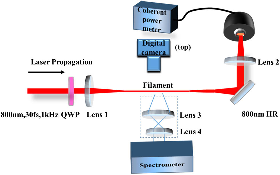
The schematic of the experimental setup is shown in Fig. 1. The femtosecond laser pulse (800 nm/1 kHz/30 fs, beam waist 6 mm) from a Ti:sapphire chirped pulse amplification (CPA) laser system was vertically polarized with pulse energy up to 8 mJ for the following measurements. The femtosecond laser pulse first passed through a quarter-wave plate (QWP) for laser polarization state control and then was focused by a plano-convex lens with a focal length of or to create stable air filaments. After filamentation, the pulse was reflected by a high-reflection mirror centered at 800 nm with a bandwidth of 100 nm and was collected to a power meter (coherent power meter LabMax-Top) by a plano-convex lens with a focal length . A digital camera (Nikon D7200) was used to capture real-color images of laser filaments from the top. Fluorescence signals from laser filaments under different polarizations were imaged from the side by a 4-f system (shown in Fig. 1) to a spectrometer (Princeton Instruments, SP-2560) for spectral analysis.
Sign up for Chinese Optics Letters TOC. Get the latest issue of Chinese Optics Letters delivered right to you!Sign up now
Figure 1.Schematic of the experimental setup. The QWP is a zero-order rotating quarter-wave plate. Lens 1–Lens 4 are UV-grade fused silica lenses with focal lengths of 30 (50), 20, 10, and 8 cm, respectively.
The polarization of the laser pulse after the QWP was characterized at the pulse energies of 3.94 mJ and 4.69 mJ. The experimental result is shown in Fig. 2(a), which fits well with the theoretical prediction of ellipticity (degree of polarization) through the definition of , where and are the minor axis and major axis of the electric field ellipse, respectively. This indicates that the ellipticity is insensitive to the pulse energies used in this work. At 45° of the QWP angle, the laser pulse was circularly polarized (CP), and at 0° or 90° the laser pulse approached linear polarization (LP).
Figure 2.(a) Measured light ellipticity for an initial LP pulse of 3.94 mJ and 4.69 mJ as a function of the rotating angle of the QWP. The red line shows the theoretical ellipticity evolution of an LP pulse after passing through a QWP. (b) Real-color images of a laser filament in air under different ellipticities. The filamenting pulse energy was 4.58 mJ and the focal length of the plano-convex lens was 50 cm. The vertical green line showed the onset position of the filament with a linear polarization pulse and the horizontal green lines were the top and bottom of the rectangular area of images that was integrated to calculate the fluorescence intensity distribution along the plasma channel.
Figure 2(b) shows the real-color images of the laser filament under different rotation angles of the QWP. The laser filament was generated in air by focusing a 4.58 mJ laser pulse by a plano-convex lens of 50 cm focal length. Obviously, the onset position of the filament and its length change when the ellipticity of the filamenting pulse is changed by rotating the QWP.
To quantitatively measure the onset position and the length of the laser filaments, the filament-induced fluorescence intensity distribution along the plasma channel was calculated by integrating the pixel intensity within identical rectangular areas defined by a pair of dotted horizontal green lines, shown in Fig. 2(b)[26]. The effective filament length was defined as the full width of the fluorescence intensity curve at , where is the standard deviation of the noise. The filament onset position was defined as the position where the fluorescence intensity reached at the leading edge of a filament. When the pulse polarization is LP and the energy is 1.872 mJ the filament onset position is defined as “0”. The onset positions of other elliptically polarized laser filaments are positive when the onset position is behind the LP one in the direction of laser propagation, i.e., the onset positions are farther away from the focusing lens. The measured filament onset position and the filament length as a function of the QWP rotation angle (polarization ellipticity) are shown in Figs. 3(a) and 3(b). The measured filament onset position and filament length as a function of the pulse energy at three fixed polarization states are shown in Figs. 3(c) and 3(d). When the polarization ellipticity was changed from LP (0° or 90°) to CP (45°), the filament onset position appears farther and farther away from the focusing lens [Fig. 3(a)], which is in agreement with the theoretical analysis in Refs. [27,28]. At the same time, the filament onset position was found to be closer and closer to the focusing lens as pulse energy was increased at a fixed polarization state [Fig. 3(c)]. Moreover, the relative filament onset distance between the LP pulse and the elliptical pulse or CP pulse became longer when a higher pulse energy was used [Fig. 3(c)]. The filament length was getting shorter and shorter as the laser polarization state changed from LP through elliptic polarization to CP [Fig. 3(b)], while the filament length was increased in a similar trend for a filamenting pulse with different polarizations as the pulse energy was increased [Fig. 3(d)].
Figure 3.(a) Onset positions of filamentation and (b) the length of filaments as a function of the QWP rotation angle. (c) Onset positions of the filamentation and (d) the length of filaments as a function of the pulse energy at three different polarization states. The effective length of the filaments was defined as the full width of the fluorescence intensity curve at , where is the standard deviation of the noise. The filament onset position was fixed at the position where the fluorescence intensity reached 3σ at the leading edge of the filaments. When the pulse polarization is LP, the filament onset position is defined as “0”. The other positions after the defined “0” position are positive, and the opposite positions before the defined “0” position are negative, which means the corresponding filament onset positions are in front of the defined “0” position and closer to the focusing lens.
We define the energy deposition ratio of a polarized light as where is the output pulse energy from the laser system for filamentation and is the rest of the pulse energy after filamentation.
Figure 4 shows the measured laser polarization dependence of the energy deposition ratio during filamentation. The energy deposition ratio in our experiments varied from a few percent up to around 16% and the energy deposition ratio is positively related to the filamenting pulse energy, i.e., the deposition ratio increased while the pulse energy increased from 2.074 mJ to 4.72 mJ. Interestingly, as the laser polarization changed from linear to circular, the deposition ratio decreased by for all pulse energies from 2.074 mJ to 4.72 mJ in our experiment.
Figure 4.Energy deposition ratio as a function of the rotation angle of the QWP under different filamenting pulse energies. The focal length of the focusing lens is 50 cm and the laser pulse duration is 30 fs.
The filament-induced UV fluorescence was collected from the side (Fig. 1). The fluorescence spectra from the LP, elliptical polarization (30° of the QWP), and CP filaments are shown in Fig. 5(a). Filaments were generated by focusing the laser pulse at an energy of 3.50 mJ and pulse duration of 30 fs through a 30 cm focal length lens (for 50 cm focal length lens, the side fluorescence signal emitted by the plasma channel is too long to be fully collected). In Fig. 5(a), the arrows marked by 1 refer to the first negative band system of ( transition); for instance, 391 nm (: 0-0), 428 nm (: 0-1), etc.[29]. Those marked by 2 refer to the second positive band system of ( transition); for instance, 337 nm (: 0-0), 358 nm (: 0-1), 380 nm (: 0-2), etc. In the transitions of , and denote the vibrational levels of upper and lower electronic states, respectively. The peak intensities of the two lines of 337 nm [2:(0-0)] and 391 nm [1:(0-0)] as a function of the rotation angle of QWP are shown in Fig. 5(b) together with the side scattered peak intensity of the filamenting pulse centered at 800 nm. When the filamenting pulse polarization was tuned from LP to CP, the 337 nm signal increased and peaked at CP, but the 391 nm signal decreased to a minimum at CP. This observation agrees with the results in Ref. [30]. Interestingly, the side scattered 800 nm filamenting pulse nicely follows the intensity trend of the 391 nm ionic line.
Figure 5.(a) Side fluorescence spectra in the range of 330–430 nm emitted by air filaments pumped by LP, elliptical polarization, and CP pulses, respectively. (b) 337 nm and 391 nm peak signals as a function of the rotation angle of the QWP together with the side-scattered peak intensity of the filamenting pulse centered at 800 nm. The focal length for filamentation is 30 cm. The laser pulse duration is 30 fs and the pulse energy is 3.50 mJ.
In order to understand the laser polarization effect on filamentation in air, a simulation based on the polarization-dependent ionization rate for molecules was performed. The extended ADK theory of ionization rate for diatomic molecules in a low frequency plane-polarized wave reads[31]with , where is the effective Coulomb charge, , is the ionization potential of the molecule, is the peak field strength, and are orbital and magnetic quantum numbers, respectively, is the normalized coefficient of the asymptotic wave function of a valence electron in a diatomic molecule, is the rotation matrix, and R is the Euler angles between the molecular axis and the field direction.
Considering an initial laser field with elliptical polarization, the extended ADK ionization rate for air molecules in a monochromatic elliptically polarized laser field is approximated[31–33] as where is the ellipticity of the laser field, F is the maximal electric-field amplitude along the major axis, and is the effective principal quantum number. The function , where is the modified Bessel function of the first kind, and the calculated parameters are listed in Table 1[31]. In our simulation, the air molecules were considered as a random distribution of 100% . The parameters were adapted from Refs. [31,34].
Cl
Parameter
Ip(eV)
l=0
l=2
l=4
N2(σg)
15.58
2.02
0.78
0.04
Table 1. Ionization Energy and the Cl Coefficients for Diatomic Molecules
To illustrate the effect of the laser ellipticity on the ionization rate of the molecule, the ratio of single-ionization rates using an elliptically polarized pulse over that using an LP pulse was calculated. The ratio as a function of laser ellipticity is shown in Fig. 6 under the three laser intensities of , , and . Clearly, the ratios of single-ionization rates decreased when the laser polarization was changed from LP (ellipticity 0) to CP (ellipticity 1). This decrease is more significant under low laser intensity. Note that although the simulation result is calculated based on an approximation of a monochromatic wave, the calculated ratio of single-ionization rates is still valid to predict the ionization behavior of a multiple-cycle femtosecond pulse because of the small contribution to the ionization rate from the laser frequencies other than the central wavelength[32,35].
Figure 6.Ratios of single-ionization rates in air for an elliptically polarized pulse over an LP pulse as a function of the ellipticity under different laser intensities.
The propagation distance of the self-focusing Gaussian beam until its collapse is rather well approximated by a semi-empirical formula when the input laser power is below 100 [2,36],where and are the wave number and the beam waist (the radius of the beam profile at the 1/e level of intensity), respectively, and is the critical power for self-focusing. For a focusing beam by a lens of focal length , the collapse distance can be estimated through [37].
When the initial pulse polarization state is changed from linear through elliptic to circular, gradually increases, finally for the CP pulse is nearly 1.5 times higher than that for the LP pulse[21,24], and the third-order nonlinearity coefficient decreases[18]. As a consequence, the collapse distance , as well as , becomes longer as increases for a fixed when the initial pulse polarization state is changed from linear through elliptic to circular. In other words, the onset position of the filaments becomes later and later as the ellipticity increases, which agrees well with our experimental observations in Figs. 3(a) and 3(c) and the results in Ref. [28]. For the initial pulse at a fixed laser polarization, the collapse distance , as well as , becomes shorter as increases. At the same time, by increasing the laser ellipticity from LP to CP, the critical power for self-focusing becomes higher, leading to the shorter filament length observed in Figs. 3(b) and 3(d), which also agrees with the theoretical prediction in Ref. [21].
As shown in our simulation in Fig. 6, the ionization ratio decreases as the ellipticity changes from LP to CP for three laser intensities. In the case of a filament in our experiment, the clamped intensity is roughly between under the free propagation condition[38,39] and under the moderately focusing condition, as in our experiment[40]. At these intensities, the ionization ratio is directly related to the electron density in the plasma channel. Therefore, the ionization-induced ionic nitrogen fluorescence signal, for instance, at 391 nm is stronger with the LP pulse compared with the signal from the CP pulse (Fig. 5) while the neutral nitrogen fluorescence at 337 nm is stronger at CP because of the stronger electron acceleration and collision within the CP pulse[41]. The higher ionization ratio for the LP pulse results in a higher electron density. This was confirmed by the scattered filamenting pulse signal at 800 nm. The scattered 800 nm signal, which is proportional to the electron density, nicely follows the ionic nitrogen fluorescence signal [Fig. 5(b)].
When a femtosecond pulse propagates in air, the effective length of the plasma channel and the average plasma density are the two main factors to deposit laser energy[42]. First, when tuning the laser ellipticity from LP through elliptic polarization to CP, the critical power for self-focusing is higher and the ionization efficiency, hence the ionization ratio, is smaller[18,43]. Consequently, the length of the plasma channel is shorter and shorter [Fig. 3(b)]. Second, the plasma density inside the filament decreases as the ellipticity increases from CP to LP, as confirmed by the scattered 800 nm signal in Fig. 5(b). Therefore, more laser energy will be used to generate a longer air filament with a higher plasma density by an LP filamenting pulse compared with that by a CP filamenting pulse; this was nicely observed in the experiments (Fig. 4).
Considering the higher-order Kerr effect (HOKE) on filamentation[44], Panov et al.[45] theoretically predicted that a CP filamenting pulse would have a maximum filament intensity, the value of the peak filament intensity was independent on the initial pulse polarization, and tended to be the peak intensity of either an LP or CP pulse. According to our experimental results and theoretical calculation on the ionization rates, the filament behaviors are highly dependent on the initial pulse polarization. In order to clarify the difference of the polarization effect on the peak intensity originating from the HOKE and plasma, experimental measurements of the peak filament intensity under different polarizations are necessary, which is also planned in the future work.
In summary, laser polarization-dependent femtosecond filamentation was experimentally studied in air. When the initial pulse polarization state rotates from LP through elliptical polarization to CP in the experiment, the relative onset of filament formation is farther and farther away from the focusing lens, the effective length of the filament is longer and longer as well, and the plasma density is lower as verified by the side fluorescence spectral intensity and the simulation of the ionization ratio of air molecules. Consequently, the shorter length of plasma filament and the lower plasma density for the CP pulse result in lower energy deposition during femtosecond filamentation in air. The results reported in this work could extend the understanding of polarized femtosecond pulse induced filaments in air.
References
[1] S. L. Chin. Femtosecond Laser Filamentation(2009).