Abstract
Five conical harmonic beams are generated from the interaction of femtosecond mid-infrared (mid-IR) pulses at a nominal input wavelength of 1997 nm with a 2D nonlinear photonic crystal with Sierpinski fractal superlattices. The main diffraction orders and the corresponding reciprocal vectors involved in the interaction are ascertained. Second and third harmonics emerging at external angles of 23.82° and 36.75° result from nonlinear erenkov and Bragg diffractions, respectively. Three pathways of fourth-harmonic generation are observed at external angles of 14.21°, 36.5°, and 53.48°, with the first one resulting from nonlinear erenkov diffraction, and the other two harmonics are generated via different cascaded processes.When a monochromatic wave passes through a homogeneous medium with its second-order nonlinear susceptibility varying in some regions, e.g., in a nonlinear photonic crystal (NPC), nonlinear diffraction can be detected for the harmonic rings or spots of the input fundamental wave[1–6]. Nonlinear diffraction, which is based on phase matching, includes nonlinear Čerenkov diffraction (NCD), nonlinear Raman–Nath diffraction (NRND), and nonlinear Bragg diffraction (NBD). For NCD, the longitudinal phase matching (LPM) is satisfied when the longitudinal direction is parallel to the incident fundamental laser beam. This phase matching can be achieved by the addition of integer multiples of the incident wave vector or the combination of the incident wave vector and reciprocal vectors. In the case of NRND, the transverse (perpendicular to the incident fundamental laser beam) phase matching (TPM) has to be satisfied. This can be achieved by the combination of the reciprocal vectors. However, for the NBD process to occur, both LPM and TPM need to be satisfied. In the past twenty years, second-harmonic generation (SHG) via various nonlinear diffractions in 1D and 2D NPCs had been the major focus[7–13]. Although high-order harmonics (HH) are very important to the field of nonlinear optics, until recently, publications on HH generation using NPCs have been almost nonexistent. Recently, there have been several significant efforts to generate third harmonics in periodic, short-range ordered or radially poled NPCs, NPC waveguide and random quadratic media by NCD and NRND[14–18]. Also, high efficiency quasi-phase-matched harmonic generation from the 2nd to 8th order have been observed within a single (LN) NPC[19]. However, fourth-harmonic generation (FHG) via nonlinear diffraction is rarely reported. The advantage of using a 2D fractal superlattice is that it may allow the freedom of optimization of many parameters such as input wavelength, harmonic order, angle, and efficiency. In this Letter, second, third, and especially multiple fourth harmonics are achieved by nonlinear diffractions in an LN NPC with Sierpinski fractal superlattices under femtosecond pulses.
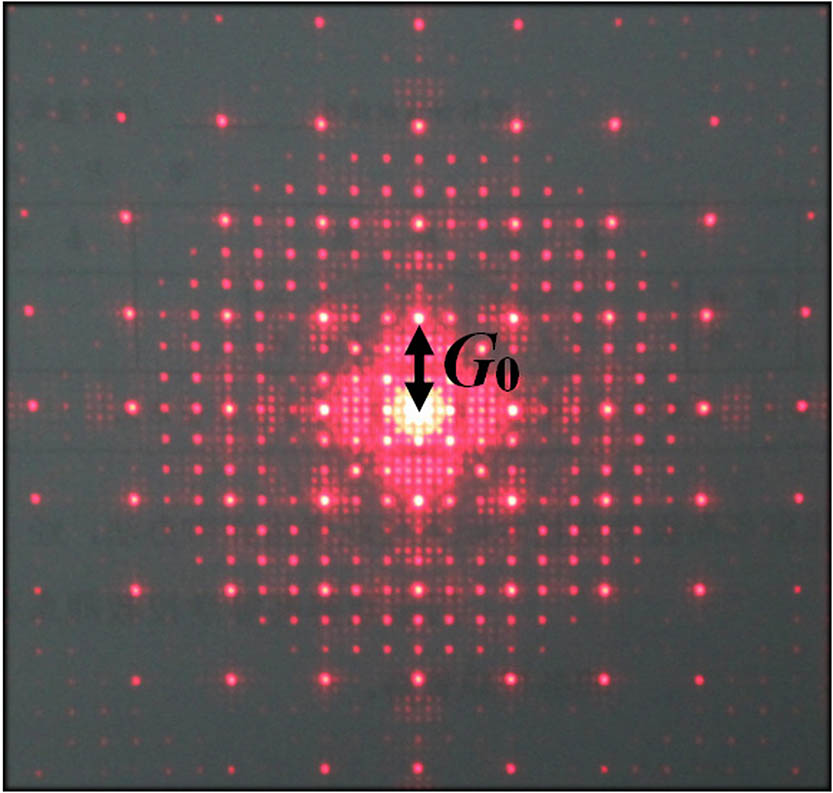
In our experiment, a fourth-order Sierpinski fractal superlattice as a unit is adopted in -cut LN NPC[20], where the second order is square and the other three orders are circles. On the basis of the fractal structure, the ratio of the distances between the two neighboring maximum circles and the two neighboring minimum circles is 27. This unit is then repeated in the plane. The interval between the repeated units is exactly the distance between the two neighboring minimum circles, i.e., 13.64 μm. The second-order susceptibilities in the circular and square regions are reversed by an external high-voltage electric field. The length, width, and thickness of the sample are 8, 8, and 0.4 mm, respectively. The diameters of the first-, third-, and fourth-order circles are 110, 12, and 5 μm, respectively, and the side length of the second-order square is 37 μm. Based on the formation of the Sierpinski superlattices, the magnitude of the basic reciprocal vector is set to be , as seen in Fig. 1. Multiple reciprocal vectors distribute in the plane.

Figure 1.Diffraction pattern of LN NPC with Sierpinski fractal superlattices.
The input fundamental 100 fs laser pulses with 2 μm central wavelength are generated from an optical parametric amplifier (OPA, Spectra-Physics) pumped by a home built 0.5 kHz Ti:sapphire laser operating at 780 nm wavelength with an 80 fs pulse width. The input fundamental wavelength is linearly (vertically) polarized with a pulse energy of approximately 30 μJ. The laser pulses are incident along the axis of the crystal so that they are perpendicular to the reciprocal vectors of LN NPC. The experimental setup is illustrated in Fig. 2. The focal length of the lens is 30 cm and the diameter of the focal spot is . The distance between the sample and the screen is denoted as . The harmonic radiation angles inside and outside the sample are defined internal and external angles, respectively, denoted as and .
Sign up for Chinese Optics Letters TOC. Get the latest issue of Chinese Optics Letters delivered right to you!Sign up now
Figure 2.Illustration of the experimental setup.
The harmonic patterns generated from the LN NPC with Sierpinski fractal superlattices are taken by a color camera, as shown in Fig. 3. At the center of the pattern, there is a red spot denoted as No. 0, which results from the collinear third-harmonic generation (THG). Around this spot, its linear diffraction spots clearly coexist, as shown in the partial enlargement of Fig. 3(a) (lower right inset). The similar red spot can also be generated in pure LN. More importantly, second, third, and multiple fourth harmonics are achieved by different nonlinear diffractions. Each harmonic on the screen is a ring formed by 6 arcs due to the 3 m symmetry of LN. As shown in Fig. 3(a), the infrared card is placed at the bottom, therefore the infrared second harmonic at 998.5 nm can be taken, and the red third harmonic can be observed clearly far away from the center. Further, with the radical distance increasing, the fourth harmonic at 499 nm is realized, i.e., the most outer ring in Fig. 3(b). It is so weak that only a part can be shown, as clearly seen in the left top inset in Fig. 3(a). Moreover, there are two other green harmonic rings. Their radii are shorter than the above outermost green ring. The second, third, and three fourth harmonics are denoted as No. 1, 2, and 3–5, respectively. The corresponding data of different harmonic rings are shown in Table 1. In the following, we will explain the coexistence of multiple harmonic rings in detail. It is noted that the experimental results are not as sensitive to the input position in the plane as that in Ref. [15], which increases the freedom of availability. It is also noted that, although efforts were made to measure the harmonic efficiency of the processes reported here, with the harmonics diverging rapidly and with the risk of damaging the sensitive energy meter by positioning it too short a distance from the back of the laser focus, it remains unknown at this point.
Figure 3.Second, third, and fourth harmonics by nonlinear diffractions in an LN NPC at a fundamental wavelength of 1997 nm. (a) Photos of centric red harmonic and its linear diffraction, and multiple harmonics. (b) Illustration of the multiple harmonics.
| No. | Wavelength (nm) | Order of Harmonic | External Conical Angle β (deg.) | Nonlinear Diffraction | Process |
|---|
| 1 | 998.5 | SHG | 23.82 | NCD | Direct |
| 2 | 665.7 | THG | 36.75 | NBD |
| 3 | 499 | FHG | 53.48 | NCD |
| 4 | 499 | FHG | 14.21 | No. 2 | TPM | Cascaded |
| 5 | 499 | FHG | 36.5 | No. 2 | TPM |
| No. 0 | LPM |
Table 1. Experimental Parameters of the Different Harmonics
According to NCD[3], the phase velocity of the nonlinear polarization wave driven by the input light field is faster than that of the harmonic. When laser beams are incident to the LN NPC as a birefringent crystal along its optical axis, double conical waves will be generated, as shown in Fig. 4(a). is the input fundamental wave vector and and are the generated Čerenkov and second harmonics from the processes [] and [], respectively. Correspondingly, and are the divergence angles of the Čerenkov and wave vectors from the incident wave vector inside the sample. From Fig. 4(a), the LPM means and . Based on the formula in quantum physics, in which and are the momentum and wave vectors, respectively, phase-matching satisfaction means momentum conservation. Theoretically, we calculate the Čerenkov conical angle as a function of the fundamental wavelength in Fig. 5, in which gray lines display the second harmonics. When the input fundamental wavelength is 1997 nm, we can get conical angles and for and waves inside the crystal. Further, on basis of the refraction index distribution in the LN ferroelectric material, we can calculate conical angles and outside the crystal. Experimentally, we measure the second harmonic conical output denoted as No. 1 outside the crystal in Fig. 3(b). It is noted that it looks like one blurry thick ring in the femtosecond laser pulses, not the clear double concentric rings under the picosecond pulses[20]. It may be attributed to the wide spectral range for the incident femtosecond pulse. The center of the generated thick Čerenkov rings is set as the reference position of the measured external angles. This external angle is about , shown as a gray dot in Fig. 5. It agrees very well with the theoretical values. By this reference, the calculated internal angle is simplified as , not and , as shown in Fig. 4(b).
Figure 4.Phase-matching diagram in nonlinear Čerenkov radiation. (a) Čerenkov second-harmonic and wave radiations. (b) Čerenkov second-, third- and fourth-harmonic waves.
Considering that the third-order susceptibility is far less than , it is widely recognized that THG is realized by the cascaded process in NPC, which includes SHG, and then the sum of SHG and the fundamental wave vector. For the Čerenkov third harmonic, LPM needs to be satisfied[17,18]. It means that and . We simulate the Čerenkov third harmonics at different fundamental wavelengths in the red lines in Fig. 5. Both inside and outside the crystal, the Čerenkov conical angles for third harmonics are wholly larger than that for second harmonics. At the input wavelength of 1997 nm, we get the internal angles and and external angles and , respectively. For 665.7 nm, third-harmonic waves are denoted as No. 2 in Fig. 3, and the measured external angle is as shown in red dot Fig. 5. This angle agrees very well with the above theoretical values.
Figure 5.Čerenkov radiation conical angle as a function of the input fundamental wavelength. The gray, red, and green lines correspond to Čerenkov second, third, and fourth harmonics. The solid and dotted lines correspond to generated and Čerenkov harmonics. Top: outside LN NPC; bottom: inside LN NPC.
Similar to the generated law of THG, the FHG can be accomplished by the cascaded process, which relates to the sum of the above Čerenkov THG and the fundamental wave vector. It means that and , i.e., LPM. In our experiment, we observe the fourth harmonic denoted as No. 3 at 499 nm in Fig. 3. Its measured external conical angle is , as shown in the green dot in Fig. 5. The calculated Čerenkov radiation angles for the fourth harmonics are larger than that for THG and even for SHG at the same fundamental wavelength in Fig. 5. For predicted 499 nm FHG and rings, the external angles are and , respectively. The theoretical results agree very well with the experimental values. Then this FHG can be attributed to NCD, i.e., LPM. The intensity of FHG is lower than that of THG, and even lower than that of SHG, which mainly results from the higher-order cascaded process.
In addition, two green fourth-harmonics No. 4 and 5 are observed at and , in Fig. 3. The intensity of No. 4 is a little stronger than that of No. 5, but both of them are weaker than the above conventional Čerenkov FHG radiation, and their external angles are less than the Čerenkov FHG angle .
In particular, for conical ring No. 4, its external angle is far less than the minimum Čerenkov external angles of FHG, i.e., about 40°, and also less than that of THG and SHG, i.e., 32.6° and 23.8° in Fig. 5, so it can not be caused by NCD. Based on the phase matching, for the fourth-harmonic wave vector , with the conical angle decreasing, the longitudinal vector will increase from the four times incident fundamental wave vector . This means that LPM is not satisfied.
It is noted that there are no other lower-order harmonic rings, such as multiple red third-harmonic rings. Considering the cascaded processes of THG and FHG, and the distribution of transverse reciprocal vectors in the plane, we assume that both LPM and TPM were simultaneously satisfied in THG as the first step in the cascaded processes of FHG, while only LPM was satisfied in SHG as the first step in the cascaded processes of THG. In the following, we will verify this assumption by a calculation.
First, we set as the average value of and in THG process, so . In the transverse direction, the involved vector is . Second, we set as the average value of and , so in the SHG process. In the transverse direction, the involved vector is . Then, it is obvious that TPM is satisfied in THG process, not in SHG process. So it can be concluded that THG No. 2 is due to NBD, i.e., both LPM and TPM. These results verify the above assumption. In fact, the research in Ref. [15] can also support our assumption. Therefore, the first step is crucial to the cascaded process.
Now the basic condition is provided for the cascaded fourth harmonics. The question remains which reciprocal vector in the transverse direction is involved in the second step. In Fig. 6, the phase-matching diagram for FHG is shown. First, we study the green fourth-harmonic No. 4 at in Fig. 3(b). By the relationship between the external and internal conical angles, the average internal angle . From Fig. 6, we can get , and TPM is perfectly satisfied by integer times of the basic reciprocal vector in LN NPC. So this process relates to NRND or TPM.
Figure 6.Phase-matching diagram in cascaded FHG process (No. 4).
For the green fourth-harmonic No. 5 at in Fig. 3, the corresponding internal angle is about . It is very close to THG No. 2. On the basis of the above law of the FHG No. 4, we also try to find the possible reciprocal vectors. Then we get in Fig. 7. The involvement of the non-integral reciprocal vector generated due to the self-similarity of the Sierpinski fractal superlattice can be used to explain the generation of the fourth-harmonic ring and why it is so weak that it is difficult to observe. It has been verified that this reciprocal vector can be effectively adopted in nonlinear processes in Ref. [20]. Then No. 5 results from No. 2 and NRND or TPM. In addition, we note that the relatively stronger third-harmonic No. 0 is generated at the center of the pattern in Fig. 3. In Fig. 7, the third harmonic and input fundamental wave vectors are collinear, then we calculate that the average internal conical angle of fourth-harmonic radiation No. 5 is 14°. Considering the calculation and experiment deviations, we can conclude that it approximately agrees with the experimental angle 15.29°. It other words, it can be partially attributed to the LPM or NCD. These two explanations for No. 5 correspond to the cascaded processes.
Figure 7.Phase matching diagram in two kinds of cascaded FHG processes (No. 5).
In conclusion, five concentric rings are observed from a LN NPC with Sierpinski fractal superlattices interacting with femtosecond mid-infrared pulses with a nominal wavelength of 1997 nm. Second and third harmonics result from NCD and NBD, respectively. Three pathways to FHG are observed. First, fourth-harmonic No. 3 can be generated by NCD based on LPM. Second, the third-harmonic ring generated by NBD is the first step in the cascaded process. In the second step, the reciprocal vectors are adopted. Then the fourth-harmonic No. 4 can be achieved by NRND based on TPM. Third, fourth-harmonic No. 5 may result from two kinds of cascaded processes. Then, it can be concluded that multiple fourth harmonics can be generated by different nonlinear diffractions or phase-matching processes by 2D fractal NPCs interacting with strong mid-infrared optical fields.
References
[1] Y. Zhang, Z. D. Gao, Z. Qi, S. N. Zhu, N. B. Ming. Phys. Rev. Lett., 100, 163904(2008).
[2] S. M. Saltiel, D. N. Neshev, R. Fischer, W. Krolikowski, A. Arie, Y. S. Kivshar. Phys. Rev. Lett., 100, 103902(2008).
[3] S. M. Saltiel, Y. Sheng, N. Voloch-Bloch, D. N. Neshev, W. Krolikowski, A. Arie, K. Koynov, Y. S. Kivshar. IEEE J. Quantum Electron., 45, 1465(2009).
[4] C. Ma, Y. Wang, L. Liu, X. Fan, A. Qi, Z. Feng, F. Yang, Q. Peng, Z. Xu, W. Zheng. Chin. Opt. Lett., 12, 030501(2014).
[5] Y. Chen, J. Zhang, H. Li. Chin. Opt. Lett., 11, 031601(2013).
[6] N. An, Y. L. Zheng, H. J. Ren, X. H. Zhao, X. W. Deng, X. F. Chen. Photon. Res., 3, 106(2015).
[7] Y. Sheng, S. M. Saltiel, W. Krolikowski, A. Arie, K. Koynov, Y. S. Kivshar. Opt. Lett., 35, 1317(2010).
[8] W. J. Wang, Y. Sheng, Y. F. Kong, A. Arie, W. Krolikowski. Opt. Lett., 35, 3790(2010).
[9] A. Shapira, A. Arie. Opt. Lett., 36, 1933(2011).
[10] H. Huang, C. P. Huang, C. Zhang, D. Zhu, X. H. Hong, J. Lu, J. Jiang, Q. J. Wang, Y. Y. Zhu. Appl. Phys. Lett., 100, 022905(2012).
[11] N. An, Y. L. Zheng, H. J. Ren, X. W. Deng, X. F. Chen. Appl. Phys. Lett., 102, 201112(2013).
[12] V. Roppo, K. Kalinowski, Y. Sheng, W. Krolikowski, C. Cojocaru, J. Trull. Opt. Express, 21, 25715(2013).
[13] A. M. Vyunishev, V. V. Slabko, I. S. Baturin, A. R. Akhmatkhanov, V. Ya. Shur. Opt. Lett., 39, 4231(2014).
[14] C. D. Chen, J. Lu, Y. H. Liu, X. P. Hu, L. N. Zhao, Y. Zhang, G. Zhao, Y. Yuan, S. N. Zhu. Opt. Lett., 36, 1227(2011).
[15] Y. Sheng, W. J. Wang, R. Shiloh, V. Roppo, A. Arie, W. Krolikowski. Opt. Lett., 36, 3266(2011).
[16] M. Ayoub, P. Roedig, J. Imbrock, C. Denz. Appl. Phys. Lett., 99, 241109(2011).
[17] Y. Sheng, W. J. Wang, R. Shiloh, V. Roppo, Y. F. Kong, A. Arie, W. Krolikowski. Appl. Phys. Lett., 98, 241114(2011).
[18] H. X. Li, S. Y. Mu, P. Xu, M. L. Zhong, C. D. Chen, X. P. Hu, W. N. Cui, S. N. Zhu. Appl. Phys. Lett., 100, 101101(2012).
[19] B. Q. Chen, C. Zhang, C. Y. Hu, R. J. Liu, Z. Y. Li. Phys. Rev. Lett., 115, 083902(2015).
[20] B. Q. Ma, B. Q. Chen, R. J. Liu, Z. Y. Li. J. Opt., 17, 085503(2015).