Author Affiliations
1Key Laboratory of Semiconductor Materials Science, Institute of Semiconductors, Chinese Academy of Sciences, Beijing 100083, China2Beijing Key Laboratory of Low Dimensional Semiconductor Materials and Devices, Beijing 100083, China3College of Materials Science and Opto-Electronic Technology, University of Chinese Academy of Sciences, Beijing 101408, China4e-mail: fqliu@semi.ac.cnshow less
Abstract
Power scaling in a broad area quantum cascade laser (QCL) tends to deteriorate beam quality with the emission of a multiple-lobe far-field pattern. In this paper, we demonstrate a coupled ridge waveguide QCL array consisting of five elements with chirped geometry. In-phase mode operation is secured by managing supermode loss with properly designed geometries of ridges. A single-lobe lateral far-field with a near diffraction limited beam pattern was obtained in the whole current dynamic range. The devices were fabricated with the wet and dry etching method. The regrowth technique of the InP:Fe insulation layer and InP:Si waveguide layer was employed. Such a structure has the potential to optimize the beam quality of the recently reported high-power broad-area QCL with a reduced cascade number.1. INTRODUCTION
Quantum cascade lasers (QCLs) have been rapidly developed and widely applied for their flexible wavelength in the midinfrared and terahertz spectrum region as portable and compact light sources [1–3]. A high-output power is pursued in many areas such as directed infrared countermeasures, remote sensing, and free-space optical communication [3]. Widening the active area is one of the most straightforward approaches to increase output power. However, simply increasing the ridge width will result in deterioration of the beam quality with the emission of a multiple-lobe far-field pattern [4,5]. Single-lobe emission has been obtained in the past with the methods of photonic crystal distributed feedback QCLs, angled-cavity QCLs, and master-oscillator power-amplifier QCLs [6–8]. Recently, phase-locked QCL arrays have been a popular approach to keep wide ridge QCL emitting with a coherent narrow beam pattern.
In fact, phase-locked arrays have been widely used for wide ridges with narrow divergence in near-infrared emitting lasers [9–13]. The phase-locked QCL arrays were first demonstrated by the coupling of evanescent-wave operating in out-of-phase mode with a two-lobe far-field pattern at 8.4 μm [14,15]. Later, Y-junction QCL arrays were demonstrated with unstable emission between in-phase and out-of-phase mode because of the spatial hole burning effect [16]. Resonant leaky-wave coupling QCL arrays were obtained by utilizing a complex regrowth process to form an antiwaveguide structure [17]. Our group has also reported evanescent wave-coupling QCL arrays with a coupled ridge waveguide and diffraction coupled QCL arrays by the Talbot effect [18–21]. Besides, the focused ion beam etching was used for wide ridge QCL emitting in a single-lobe far-field pattern [22]. However, these phase-locked QCL arrays usually either emit with high-order supermodes under high injection current [16,18,19] or produce extra waveguide loss resulting in a high threshold current density [20–22].
In this paper, we demonstrate a chirped couple ridge waveguide QCL array with a stable fundamental supermode far-field pattern at . A near diffraction limited (DL) divergence angle of 9.4° is obtained in the whole current dynamic range, which is defined as the difference of the maximum and threshold current. Because the recent studies on the reduced stage QCLs showed attractive results with an output power up to 4 W [3,23], power scaling in QCL using broad-area stripes with reduced cascade number has obtained continuous wave (CW) operation [24–26]. Once the chirped coupled ridge waveguide structure is employed in wide ridge QCL with a reduced cascade number, a near DL far-field pattern in CW mode will have the potential to be obtained. In addition, this method has lower waveguide loss than divided active region QCL arrays because the active region of devices is not destroyed.
Sign up for Photonics Research TOC. Get the latest issue of Photonics Research delivered right to you!Sign up now
2. WAFER GROWTH AND DEVICE FABRICATION
The QCL wafer was grown on an n-doped (Si, ) InP substrate wafer by solid-source molecular beam epitaxy (MBE) using an active-region structure similar to Ref. [27]. The active core structure presented in this work contains 40 periods of strain-compensated quantum wells and barriers. The specific layer sequence of one period, in nanometers, is as follows (layer thickness in nanometers): 4/1.7/0.9/5.06/0.9/4.7/1/3.9/1.8/3.2/1.7/2.8/1.9/2.7/2.8/2.6, where barrier layers are in bold, well layers are in roman, and n-doped layers () are underlined. The whole wafer structure before the fabrication is 4.5 μm lower InP cladding (Si, ), 0.3 μm thick layer (Si, ), 40 active/injector stages, 0.3-μm-thick layer (Si, ).
After the epitaxy in MBE, a traditional lithograph process was used to define the chirped arrays within a thin photoresist deposited on a 450 nm thick layer used as a hard mask. The pattern was transferred from the photoresist to the layer using inductively coupled plasma etching. Then, 2 μm thick semi-insulating InP:Fe was selectively regrown by a metal organic vapor phase epitaxy (MOVPE), for the purposes of thermal dissipation, optical coupling, and electrical insulation, as shown in Fig. 1(a), and highlighted by the region enclosed by the yellow lines in Fig. 1(b). The residual was removed with wet etching approach, which defined the width of the active region. Next, a 3 μm InP upper cladding layer (Si, ) was grown by MOVPE, followed with a 0.15 μm InP gradually layer doped (changing from to ) and 0.6 μm highly doped InP cladding layer (Si, ). Next, the contact metal, a 300 nm thick gold layer was evaporated to bury the devices. An additional 5 μm thick layer of gold electroplating was deposited. Then, the wafer substrate was thinned down to 120 μm, and the Ge/Au/Ni/Au metal contacts were formed as the bottom contact. Finally, the wafer was cleaved into 2 mm long, and the devices were soldered epilayer side down onto the copper heat sink with indium solder. Figures 1(a) and 1(b) show the schematic of the device’s cross section from the facet direction and the scanning electron microscopy (SEM) image of the device facet, respectively.
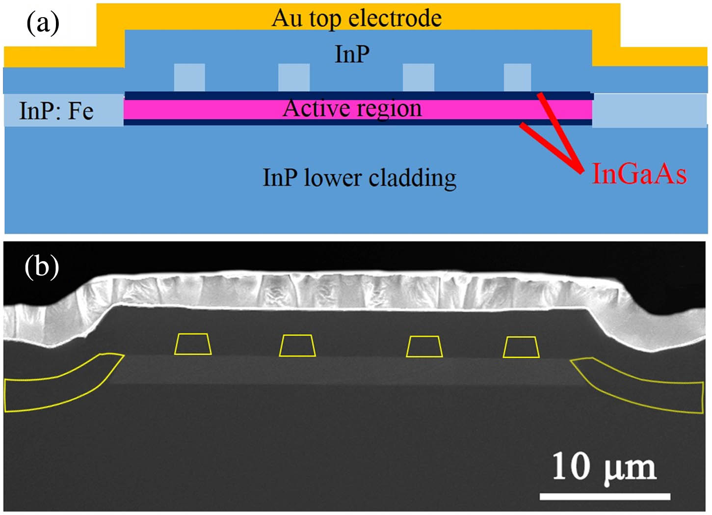
Figure 1.(a) Schematic of device cross section from the facet direction. (b) SEM image of the device facet; region enclosed by the yellow line denotes the regrown InP:Fe.
3. RESULT AND DISCUSSION
The far-field distributions of the chirped coupled ridge waveguide QCL arrays at different injection currents were measured using the lock-in technique and a room temperature mercury-cadmium-telluride (MCT) detector. The MCT detector was placed away from the array devices, which are mounted on a rotation stage controlled by a computer with a resolution of 0.05°. Figure 2 shows measured and simulated lateral far-field radiation patterns of the devices. The far-field distributions show a strong central lobe at 0°, indicating the in-phase supermode operation according to the couple-mode theory [9]. For a given optical power, a DL beam has the highest brightness. Considering the light extension from the active region to side waveguides of about 6–10 μm in total, the DL far-field divergence is 9.1°–9.9°. The dashed red line shows the theoretical far-field distribution, which is almost overlapped with measured results. The measured full width at half-maximum (FWHM) of the far-field pattern is nearly diffraction limited 9.4°. Unlike the uniform coupled ridge waveguide structure in Ref. [20], the far-field patterns have almost no extension at higher angles in the whole current dynamic range from 2.1 to 3.3 A, which is coincident with the loss difference between high-order and fundamental supermode in Fig. 3(a). Totally, our devices show a DL single-lobe far-field pattern with negligible beam steering as in Ref. [28] in the whole current dynamic range.

Figure 2.Measured (solid) and simulated (red dashed) lateral far-field radiation patterns for the coupled ridge waveguide QCL chirped devices. The driving currents changed from 2.1 to 3.3 A with a step of 0.3 A at a 5 kHz repetition frequency and 1% duty cycle pulsed mode operation.
Figure 3.(a) Losses of different order supermodes for five-element QCL chirped and uniform arrays of coupled ridge waveguide with different geometry. The ridge width of the chirped array elements is 4, 6, , 6, 4 μm with changing from 7 to 11 μm at a step of 1 μm; the interspace of chirped arrays is 2 μm. The uniform arrays center-to-center space is 8, and the interspace is 2 μm. (b) Losses of the fundamental and high-order supermodes and loss difference as a function of the centered ridge width for the chirped arrays. (c) Calculated near-field profile of five-element chirped structure taken with finite element method; red lines illustrate the current distribution in the QCL array showing the InP:Fe region without current distribution. The simulation is based on the finite element software COMSOL.
The stable fundamental supermode emission means that the fundamental supermode has lower modal loss than the high-order ones. The supermode loss in QCL arrays consists of a modal mirror loss and waveguide loss. The difference of modal mirror loss for the fundamental and high-order modes is quite small in coupled ridge waveguide arrays because it is inversely proportional to the transverse dimension of the active region [29]. Therefore, waveguide loss plays an essential role in mode discrimination of the fundamental supermode and high-order supermode. The modal losses of the fundamental and high-order supermodes of different geometry were simulated with COMSOL, as shown in Fig. 3(a). For both chirped arrays and uniform array, the fundamental supermodes have the lowest modal loss. The difference between high-order supermode and fundamental supermode in the uniform array is relatively lower than that of the chirped arrays. This means that the chirped structure of interelement widths helps somewhat with intermodal discrimination. In the chirped array, the higher-order supermode can be suppressed by tailoring the lateral gain distribution across the array such that the near-field envelopes of the fundamental and the higher-order supermodes can differ appreciably [9]. Figure 3(b) shows the losses of the fundamental and high-order supermodes and loss difference as a function of the central ridge width . Both the fundamental and high-order modal losses decrease when the central ridge width increases from 7 to 11 μm, so does the loss difference of the fundamental and high-order supermodes. Therefore, to achieve the fundamental supermode emitting preferentially and to make the loss not too high at the same time, a central ridge width is selected. Figure 3(c) shows the results of a numerical 2D simulation of the near-field electric field intensity distribution (patterns) of the fundamental mode and the current distribution (red lines) of five-element chirped coupled ridge waveguide QCL arrays. The transverse electric field intensity distribution can be applied to deduce the far-field pattern as shown by the red dashed line in Fig. 2, which presents an in-phase fundamental supermode operation. The in-phase array mode peaks under the two central InP:Fe ridges, making it similar to the in-phase mode of a four-element, evanescent-wave-coupled array with somewhat low-index semi-infinite regions away from its edges [14]. The red lines show the nonuniform current distribution in the waveguide because the insulation InP:Fe blocks flow of the current. A good thermal dissipation is expected because the whole waveguide is an InP structure.
The emitted optical power was measured with a calibrated thermopile detector placed directly in front of the laser facet. The spectrum measurements were performed using a Fourier transform infrared spectrometer with resolution in rapid scan mode. Figure 4 shows the power-current (P-I) characteristic under pulsed mode with the current driver maintained at 5 kHz with a duty cycle of 1%. For a wide QCL chirped array, a total peak power of 840 mW is obtained at 298 K with a threshold current density of and a slope efficiency of 0.4 W/A, as shown by the blue line. In contrast, the single laser device with a wide ridge shows a maximum peak power of 360 mW, a threshold current density of , and a slope efficiency of 0.48 W/A. The output power of single facet per unit area in phase-locked arrays and single laser is and , respectively. It can be thought that the output power scales almost linearly with the area of the active region of the arrays. The small reduction of the slope efficiency may be caused by thermal accumulation. When the cascade number of QCL active region is reduced, the chirped coupled ridge waveguide arrays may operate in CW mode. The inset of Fig. 4 shows the lasing spectrum of the phase-locked arrays at room temperature and 1.3 times threshold current. The center wavelength was measured to be 7.6 μm with a multimode nature resulting from the lack of a longitudinal-mode selection mechanism. The single-mode spectrum can be achieved by introducing a distributed feedback grating on the top cladding layer.
Figure 4.Total peak power change as a function of the current at 298 K for a wide chirped array (blue line) and a wide single laser (green line). The current driver is maintained at 5 kHz with a duty cycle of 1%. Inset is the lasing spectrum of the chirped arrays at 1.3 times threshold current, which peaks at .
4. CONCLUSION
In summary, we demonstrate chirped coupled ridge waveguide QCL arrays of 7.6 μm operating at in-phase mode with a DL divergence. The FWHM of the far-field pattern has no extension in the whole current dynamic range from the threshold to the full power current. Further studies should be taken on the devices with the active region of reduced cascade number. We expect a CW operation to be obtained on broad area QCL arrays with DL beam quality. Once optimized, the devices have potential for high brightness diffraction-limited broad-area QCL arrays.
Acknowledgment
Acknowledgment. The authors would like to thank Ping Liang and Ying Hu for their help in device processing.
References
[1] J. Faist, F. Capasso, D. L. Sivco, C. Sirtori, A. L. Hutchinson, A. Y. Cho. Quantum cascade laser. Science, 264, 553-556(1994).
[2] M. S. Vitiello, G. Scalari, B. Williams, P. De Natale. Quantum cascade lasers: 20 years of challenges. Opt. Express, 23, 5167-5182(2015).
[3] A. Lyakh, C. K. N. Patel, E. Tsvid, M. Suttinger, P. Figueiredo, R. Go. Progress in high-power continuous-wave quantum cascade lasers. Appl. Opt., 56, H15-H23(2017).
[4] Y. Bai, S. Slivken, S. R. Darvish, A. Haddadi, B. Gokden, M. Razeghi. High power broad area quantum cascade lasers. Appl. Phys. Lett., 95, 071101(2009).
[5] Y. Zhao, F. Yan, J. Zhang, F. Liu, N. Zhuo, J. Liu, L. Wang, Z. Wang. Broad area quantum cascade lasers operating in pulsed mode above 100°C λ ∼ 4.7 μm. J. Semicond., 38, 074005(2017).
[6] B. Gökden, Y. Bai, N. Bandyopadhyay, S. Slivken, M. Razeghi. Broad area photonic crystal distributed feedback quantum cascade lasers emitting 34 W at λ ∼ 4.36 μm. Appl. Phys. Lett., 97, 221104(2010).
[7] S. Menzel, L. Diehl, C. Pflügl, A. Goyal, C. Wang, A. Sanchez, G. Turner, F. Capasso. Quantum cascade laser master-oscillator power-amplifier with 1.5 W output power at 300 K. Opt. Express, 19, 16229-16235(2011).
[8] D. Heydari, Y. Bai, N. Bandyopadhyay, S. Slivken, M. Razeghi. High brightness angled cavity quantum cascade lasers. Appl. Phys. Lett., 106, 091105(2015).
[9] E. Kapon, J. Katz, A. Yariv. Supermode analysis of phase-locked arrays of semiconductor lasers. Opt. Lett., 9, 125-127(1984).
[10] M. Cronin‐Golomb, A. Yariv, I. Ury. Coherent coupling of diode lasers by phase conjugation. Appl. Phys. Lett., 48, 1240-1242(1986).
[11] D. Mehuys, K. Mitsunaga, L. Eng, W. Marshall, A. Yariv. Supermode control in diffraction‐coupled semiconductor laser arrays. Appl. Phys. Lett., 53, 1165-1167(1988).
[12] J. R. Leger. Lateral mode control of an AlGaAs laser array in a Talbot cavity. Appl. Phys. Lett., 55, 334-336(1989).
[13] E. Kapon, C. Lindsey, J. Katz, S. Margalit, A. Yariv. Chirped arrays of diode lasers for supermode control. Appl. Phys. Lett., 45, 200-202(1984).
[14] G. M. de Naurois, M. Carras, G. Maisons, X. Marcadet. Effect of emitter number on quantum cascade laser monolithic phased array. Opt. Lett., 37, 425-427(2012).
[15] G. M. D. Naurois, M. Carras, B. Simozrag, O. Patard, F. Alexandre, X. Marcadet. Coherent quantum cascade laser micro-stripe arrays. AIP Adv., 1, 032165(2011).
[16] A. Lyakh, R. Maulini, A. Tsekoun, R. Go, C. K. N. Patel. Continuous wave operation of buried heterostructure 4.6 μm quantum cascade laser Y-junctions and tree arrays. Opt. Express, 22, 1203-1208(2014).
[17] C. Sigler, C. A. Boyle, J. D. Kirch, D. Lindberg, T. Earles, B. Dan, L. J. Mawst. 4.7 μm-emitting near-resonant leaky-wave-coupled quantum cascade laser phase-locked arrays. IEEE J. Sel. Top. Quantum Electron., 23, 1200706(2017).
[18] Y. H. Liu, J. C. Zhang, F. L. Yan, F. Q. Liu, N. Zhuo, L. J. Wang, J. Q. Liu, Z. G. Wang. Coupled ridge waveguide distributed feedback quantum cascade laser arrays. Appl. Phys. Lett., 106, 142104(2015).
[19] L. Wang, J. Zhang, Z. Jia, Y. Zhao, C. Liu, Y. Liu, S. Zhai, Z. Ning, X. Xu, F. Liu. Phase-locked array of quantum cascade lasers with an integrated Talbot cavity. Opt. Express, 24, 30275-30281(2016).
[20] F. L. Yan, J. C. Zhang, Z. W. Jia, N. Zhuo, S. Q. Zhai, S. M. Liu, F. Q. Liu, Z. G. Wang. High-power phase-locked quantum cascade laser array emitting at λ ∼ 4.6 μm. AIP Adv., 6, 035022(2016).
[21] Z. Jia, L. Wang, J. Zhang, Y. Zhao, C. Liu, S. Zhai, N. Zhuo, J. Liu, L. Wang, S. Liu, F. Liu, Z. Wang. Phase-locked array of quantum cascade lasers with an intracavity spatial filter. Appl. Phys. Lett., 111, 061108(2017).
[22] R. Kaspi, S. Luong, C. Yang, C. Lu, T. C. Newell, T. Bate. Extracting fundamental transverse mode operation in broad area quantum cascade lasers. Appl. Phys. Lett., 109, 211102(2016).
[23] A. Lyakh, M. Suttinger, R. Go, P. Figueiredo, A. Todi. 5.6 μm quantum cascade lasers based on a two-material active region composition with a room temperature wall-plug efficiency exceeding 28%. Appl. Phys. Lett., 109, 121109(2016).
[24] P. Figueiredo, M. Suttinger, R. Go, A. Todi, S. Hong, E. Tsvid, C. K. N. Patel, A. Lyakh. Continuous wave quantum cascade lasers with reduced number of stages. IEEE Photon. Technol. Lett., 29, 1328-1331(2017).
[25] W. T. Masselink, M. P. Semtsiv, A. Aleksandrova, S. Kurlov, W. T. Masselink, M. P. Semtsiv, A. Aleksandrova, S. Kurlov. Power scaling in quantum cascade lasers using broad-area stripes with reduced cascade number. Opt. Eng., 57, 011015(2017).
[26] M. Suttinger, R. Go, P. Figueiredo, A. Todi. Power scaling and experimentally fitted model for broad area quantum cascade lasers in continuous wave operation. Opt. Eng., 57, 011011(2017).
[27] P. Jouy, C. Bonzon, J. Wolf, E. Gini, M. Beck, J. Faist. Surface emitting multi-wavelength array of single frequency quantum cascade lasers. Appl. Phys. Lett., 106, 071104(2015).
[28] Q. Y. Lu, Y. Bai, N. Bandyopadhyay, S. Slivken, M. Razeghi. 2.4 W room temperature continuous wave operation of distributed feedback quantum cascade lasers. Appl. Phys. Lett., 98, 181106(2011).
[29] N. Yu, L. Diehl, E. Cubukcu, C. Pflügl, D. Bour, S. Corzine, J. Zhu, G. Höfler, K. B. Crozier, F. Capasso. Near-field imaging of quantum cascade laser transverse modes. Opt. Express, 15, 13227-13235(2007).


