
Kazuhisa Nakajima. Conceptual designs of a laser plasma accelerator-based EUV-FEL and an all-optical Gamma-beam source[J]. High Power Laser Science and Engineering, 2014, 2(4): 04000e31
- High Power Laser Science and Engineering
- Vol. 2, Issue 4, 04000e31 (2014)
Abstract
1. Introduction
To date, intense research has been carried out on laser plasma acceleration concepts[
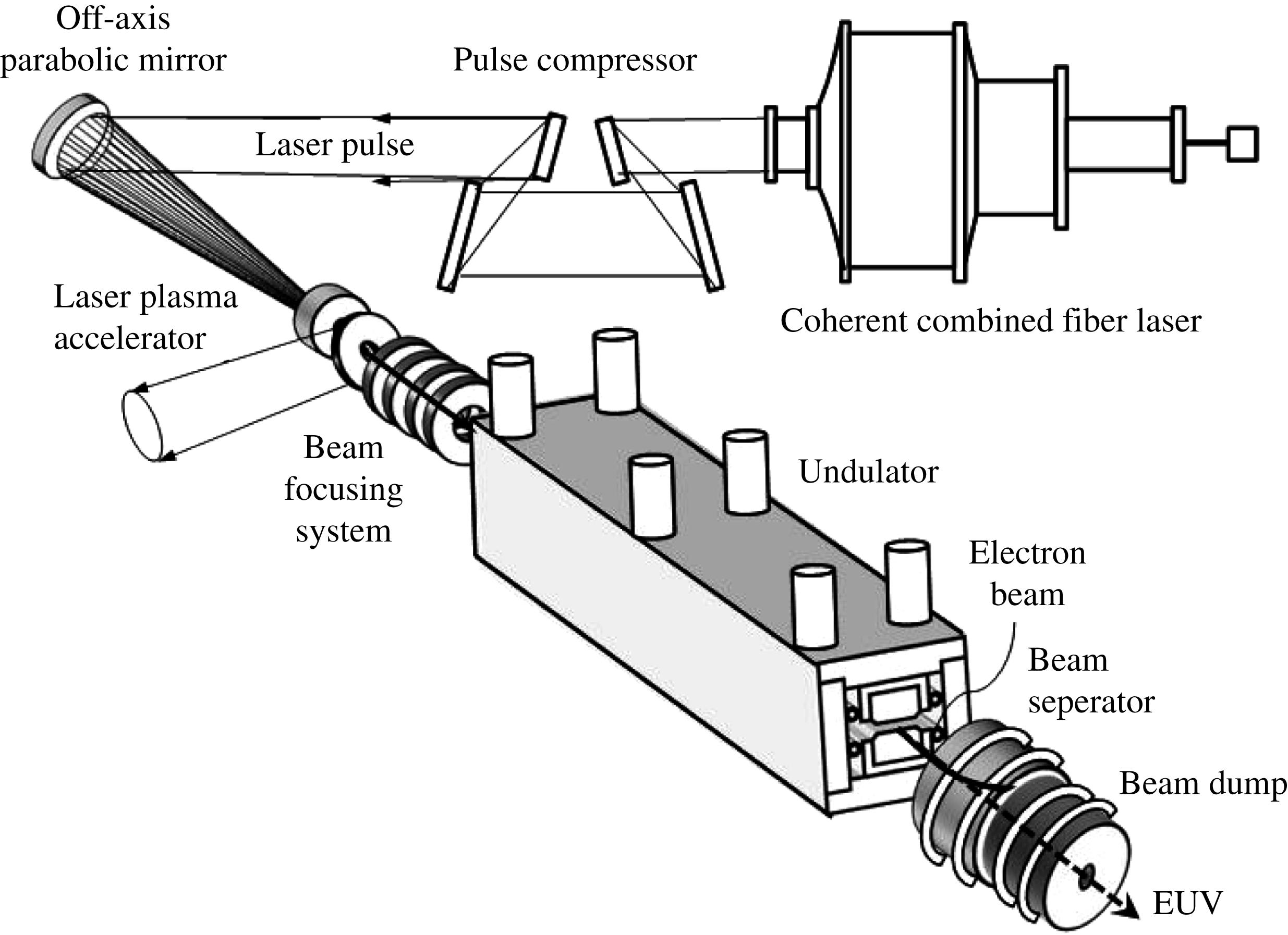
Here we present an extreme ultraviolet (EUV) radiation source for next-generation lithography and a laser Compton Gamma-beam source for nuclear physics research. EUV lithography with wavelengths below 13.5 nm is capable of providing resolution below 30 nm in semiconductor manufacturing. We propose a self-amplified spontaneous emission (SASE) free electron laser (FEL) driven by relativistic electron beams from laser plasma accelerators. For example, this FEL system, capable of generating an average EUV power of 1 kW at 13.5 nm, comprises a fiber-based chirped pulse amplification (CPA) laser delivering a 1 MW average laser power, a 5 cm gas cell-type plasma accelerator producing a 660 MeV electron beam with a 1.6% relative energy spread and a 0.5 nC charge, and a 1 m long undulator with a 15 mm period and a 1.4 T peak magnetic field.
High-quality Gamma beams generated from inverse Compton scattering off relativistic electron beams interacting with an intense laser pulse have aroused interest in photonuclear physics and nuclear astrophysics research, the characterization of nuclear materials or radioactive waste and so on. We present a table-top all-optical laser plasma accelerator-based Gamma-beam source comprising a high-power laser system with synchronous dual outputs, a laser plasma accelerator producing 300–900 MeV electron beams, and scatter optics whereby the laser pulse is focused onto the electron beam to generate a Gamma beam via Compton scattering with photon energies of 2–20 MeV.
Sign up for High Power Laser Science and Engineering TOC. Get the latest issue of High Power Laser Science and Engineering delivered right to you!Sign up now
2. Design of laser plasma accelerators for driving electron beams
2.1. Accelerator stage
Most of the laser plasma acceleration experiments that have successfully demonstrated the production of quasi-monoenergetic electron beams with a narrow energy spread have been elucidated in terms of self-injection and acceleration mechanisms in the bubble regime[ , peak power
  , intensity
  , and focused spot radius
  is characterized by a normalized vector potential
  with respect to the electron rest energy
  , given for the linear polarization as
 (1)
(1) in the bubble frame moving in a plasma with velocity
  , i.e.,
  , where
  is the plasma wavenumber evaluated with a plasma frequency
  , an unperturbed on-axis electron density
  and the classical electron radius
  , and
, and  is the non-relativistic wave-breaking field, approximately given by
  . In the bubble regime for
  , since an electron-evacuated cavity shape is determined by balancing the Lorentz force of the ion sphere exerted on the electron sheath with the ponderomotive force of the laser pulse, the bubble radius
  is approximately given as
  [
[ , where
  represents a factor taking into account the difference between the theoretical estimation and the accelerating field reduction due to the beam loading effects.
Here we consider the self-guided case, where a drive laser pulse propagates in a homogeneous density plasma. The equations of longitudinal motion of an electron with normalized energy  and longitudinal velocity
  are written approximately as[
 (2)
(2) (
( ) is the longitudinal coordinate of the bubble frame moving at a velocity of
  , taking into account diffraction at the laser pulse front that etches back at a velocity
  [
[ , and
, and  is assumed. Integrating Equations (
 (3)
(3) is the injection energy. Hence, the maximum energy gain is obtained at
  as
as  (4)
(4) is the correction factor of the relativistic factor for the group velocity in a uniform plasma for a self-guided pulse, i.e.,
  , obtained from[
 (5)
(5)
 is the critical plasma density. The dephasing length
  for the self-guided bubble regime is given by
  (6)
(6) , the operating plasma density is determined from Equation (
 (7)
(7) (8)
(8) (9)
(9) . Thus, the required pulse duration for self-guiding of the drive laser pulse is given by
 (10)
(10) (11)
(11) is the dimensionless matched spot radius given by[
 (12)
(12) (13)
(13) (14)
(14)2.2. Beam loading effects
In laser wakefield acceleration, an accelerated electron beam induces its own wakefield and cancels the laser-driven wakefield. Assuming the beam loading efficiency  defined by the fraction of plasma wave energy absorbed by particles of the bunch with a root mean square (r.m.s.) radius
  , the beam-loaded field is given by
  , where
  is the accelerating field without beam loading, given by
  for the bubble regime
  . Thus, a loaded charge is calculated as[
 (15)
(15) (16)
(16) for accelerating charge
  up to energy
  is obtained by solving the equation
  (17)
(17) is defined as
  (18)
(18)2.3. Injector stage
Electron beams can be produced and accelerated in the injector stage driven by the same laser pulse as that in the accelerator stage, relying on a self-injection mechanism such as the expanding bubble self-injection mechanism[ . At a plasma density
  in the injector, the required minimum laser field is
  . The maximum number of trapped electrons saturates at approximately
  at a gas length
  for a plasma density
  with a nitrogen concentration of
  and laser parameters of
  and
and  due to the beam loading effects and initially trapped particle loss from the separatrix in the phase space. From the particle-in-cell (PIC)-simulation results[
 (19)
(19) , the electron charge
  trapped inside a bunch with radius
  at
at  is estimated as
  (20)
(20) .
.2.4. Design of a SASE FEL
In the SASE FEL process, coupling the electron bunch with a co-propagating undulator radiation field induces an energy modulation of electrons that yields current modulation of the bunch due to the dispersion of the undulator dipole fields, known as microbunching. It means that the electrons are grouped into small bunches separated by a fixed distance that resonantly coincides with the wavelength of the radiation field. Consequently, the radiation field can be amplified coherently. In the absence of an initial resonant radiation field, a seed may build up from spontaneous incoherent emission in the SASE process.
The design of the FEL-based EUV light source is carried out using one-dimensional FEL theory as follows[ and peak magnetic field
  at a resonant wavelength
  given by
 (21)
(21) is the relativistic factor of the electron beam energy
  , and
, and  is the undulator parameter, which is related to the maximum electron deflection angle
  . In the high-gain regime required for the operation of a SASE FEL, an important parameter is the Pierce parameter
  , given by
  (22)
(22) is the beam current,
  is the Alfven current,
  is the r.m.s transverse size of the electron bunch, and the coupling factor is
  for a helical undulator and
  for a planar undulator, where
  and
and  and
and  are Bessel functions of the first kind. Another important dimensionless parameter is the longitudinal velocity spread
  of the beam normalized by the Pierce parameter:
  (23)
(23) is the relativistic r.m.s. energy spread,
  is the r.m.s. transverse emittance,
  is the beta function provided by the guiding field (undulator plus external focusing) and
  is the normalized emittance, defined as
  , assuming that the beta function is constant along the length of the undulator. The
  -folding gain length
  over which the power grows exponentially according to
  is given by
  (24)
(24) and a normalized longitudinal velocity spread
  sufficiently low compared to unity, which means a sufficiently small energy spread
  and
and  . This expression applies to a moderately small beam size
  such that the diffraction parameter
  , where
  is defined as
  (25)
(25) required to saturate the amplification can be expressed as
  (26)
(26) and
and  are the input power and the saturated power, which are related to the electron beam power
  according to
  (27)
(27) is the number of electrons per wavelength, given by
  .
.| Case | A | B | C | D | E |
|---|---|---|---|---|---|
| Laser | |||||
Laser wavelength ( ) ) | 1 | 1 | 1 | 1 | 1 |
| Average laser power (MW) | 1.63 | 1.24 | 1.19 | 1.22 | 1.27 |
| Repetition rate (MHz) | 1.22 | 0.515 | 0.315 | 0.223 | 0.168 |
| Laser energy per pulse (J) | 1.34 | 2.40 | 3.79 | 5.52 | 7.57 |
| Peak power (TW) | 29 | 43 | 59 | 75 | 93 |
| Pulse duration (fs) | 46 | 56 | 65 | 73 | 82 |
Matched spot radius ( ) ) | 19 | 23 | 27 | 30 | 34 |
| Laser plasma accelerator | |||||
| Electron beam energy (MeV) | 243 | 427 | 659 | 937 | 1257 |
Plasma density ( ) ) | 8.3 | 5.6 | 4.2 | 3.2 | 2.6 |
| Accelerator length (mm) | 18 | 32 | 51 | 74 | 102 |
| Charge per bunch (nC) | 0.5 | 0.5 | 0.5 | 0.5 | 0.5 |
Field reduction factor  | 0.223 | 0.267 | 0.302 | 0.325 | 0.364 |
| Bunch duration (fs) | 10 | 10 | 10 | 10 | 10 |
| Energy spread (%) |  1.1 1.1 |  1.5 1.5 |  1.6 1.6 |  1.6 1.6 |  1.6 1.6 |
Transverse beam size ( ) ) | 25 | 25 | 25 | 25 | 25 |
| Peak current (kA) | 50 | 50 | 50 | 50 | 50 |
| Average beam power (kW) | 148 | 110 | 104 | 104 | 105 |
| Efficiency of laser to beam (%) | 9.1 | 8.9 | 8.7 | 8.5 | 8.3 |
| Free electron laser | |||||
| Undulator period (mm) | 5 | 10 | 15 | 20 | 25 |
| Radiation wavelength (nm) | 13.5 | 13.5 | 13.5 | 13.5 | 13.5 |
| Gap (mm) | 1 | 2 | 3 | 4 | 5 |
| Peak magnetic field (T) | 1.425 | 1.425 | 1.425 | 1.425 | 1.425 |
Undulator parameter  | 0.666 | 1.33 | 2.00 | 2.66 | 3.33 |
| Pierce parameter (%) | 1.12 | 1.51 | 1.60 | 1.60 | 1.57 |
| Gain length (mm) | 41 | 61 | 86 | 115 | 146 |
| Saturation length (mm) | 499 | 721 | 1016 | 1355 | 1723 |
| Number of periods | 100 | 72 | 68 | 68 | 69 |
| Spectral bandwidth (%) | 1.0 | 1.4 | 1.5 | 1.5 | 1.5 |
R.m.s. radiation cone angle ( ) ) | 116 | 97 | 82 | 71 | 63 |
| Input power (MW) | 0.94 | 3.03 | 5.26 | 7.48 | 9.72 |
| Saturated power (GW) | 82 | 194 | 317 | 451 | 596 |
| Duration of EUV pulse (fs) | 10 | 10 | 10 | 10 | 10 |
| Average EUV power (kW) | 1 | 1 | 1 | 1 | 1 |
| Efficiency of EUV generation (%) | 0.061 | 0.081 | 0.084 | 0.082 | 0.079 |
Table 1. Parameters for laser plasma accelerator-based EUV FEL light sources.
For an EUV light source based on a FEL, a planar undulator comprising alternating dipole magnets is used, e.g., a pure permanent magnet (PPM) undulator with  (Nd–Fe–B) blocks or a hybrid undulator comprising PPMs and ferromagnetic poles, e.g., a high saturation cobalt steel such as Vanadium Permendur or a simple iron. For a hybrid undulator, the thickness of the pole and magnet is optimized in order to maximize the peak field. The peak field
  of the gap is estimated in terms of the gap
  and period
  according to
  for a gap range
  , where
  ,
,  and
and  for the hybrid undulator with Vanadium Permendur. Table
  mm (Case A), 2 mm (Case B), 3 mm (Case C), 4 mm (Case D), and 5 mm (Case E), respectively. The bunch duration of the electron beam in the injector stage at a plasma density of
  is assumed to be
  10 fs full-width at half-maximum (FWHM), based on a measurement of the electron bunch duration in a recent laser wakefield acceleration experiment[
 , where
  is the final beam energy in the accelerator stage, is assumed to be of the order of 10% in the injector stage. After acceleration up to 10 times higher energy in the accelerator stage, the relative energy spread at the final beam energy is reduced to
  due to adiabatic damping in the longitudinal beam dynamics. The transverse beam size is tuned by employing a beam focusing system. Figure
2.5. Design of all-optical Gamma-beam source
The design of a Gamma-beam source based on inverse Compton scattering is carried out by using a result of quantum electrodynamics on photon–electron interactions, namely, the Klein–Nishina formula, which gives the differential cross section of photons scattered from a single electron in the lowest order of quantum electrodynamics. In Compton scattering of a laser photon with energy  (
( for laser wavelength
  off a beam electron, the maximum energy of the scattered photon is given by
  , where
  is the relativistic factor for an electron beam energy
  with electron rest mass
  and the factor
  . In the laboratory frame, the differential cross section of Compton scattering[
 (28)
(28) is the energy of a scattered photon normalized by the maximum photon energy and
  (
( with the classical electron radius
  . In the laboratory frame, the scattering angle
  of the photon is given by
  . Integrating the differential cross section over
  , the total cross section of Compton scattering becomes
  (29)
(29) for an electron beam energy
  . The fractional cross section for the photon energy range
  is given by
  (30)
(30) . All photons in this energy range are scattered in the forward direction within a half-cone angle
  . For an electron beam interacting with a laser pulse at an angle of
  in the horizontal plane (
 -plane), the luminosity representing the probability of collisions between electron and laser beams per unit cross section per unit time is obtained by
  , where
  is the number of electrons contained in the electron bunch,
  is the number of photons per laser pulse,
  is the repetition rate of laser pulses, and
  is the area where the two beams overlap, given by
  (31)
(31) and
and  are the r.m.s. horizontal and vertical sizes of the electron beam,
  is the r.m.s. bunch length of the electron beam,
  and
and  are the r.m.s. horizontal and vertical spot sizes of the laser beam, and
  is the r.m.s. pulse length of the laser beam. For a head-on collision providing efficient Gamma-beam production, the crossing angle between the electron and laser beams is chosen to be
  . Tuning the beam focusing system and the interaction optics so as to give
  , the luminosity turns out to be
  , where
  is the laser spot radius at the interaction point. Using
  and
and  , where
  is the charge of the electron bunch and
  is the energy of a scatter pulse with peak power
  and duration
  , the luminosity is calculated as
  (32)
(32) is the focused intensity of the scatter pulse at the interaction point. Thus the Gamma-beam flux is given by
  (33)
(33) is estimated as
  (34)
(34)Table
| Case | A | B | C | D | E |
|---|---|---|---|---|---|
| Laser plasma accelerator | |||||
Laser wavelength ( ) ) | 0.8 | 0.8 | 0.8 | 0.8 | 0.8 |
| Repetition rate (Hz) | 10 | 10 | 10 | 10 | 10 |
| Laser energy per pulse (J) | 1.78 | 2.56 | 3.68 | 4.55 | 5.31 |
| Peak power (TW) | 41 | 52 | 66 | 77 | 85 |
| Pulse duration (fs) | 43 | 49 | 55 | 59 | 62 |
Matched spot radius ( ) ) | 18 | 20 | 23 | 24 | 26 |
| Electron beam energy (MeV) | 326 | 461 | 654 | 802 | 928 |
Plasma density ( ) ) | 9.2 | 7.3 | 5.7 | 4.9 | 4.5 |
| Accelerator length (mm) | 24 | 34 | 50 | 61 | 72 |
| Charge per bunch (nC) | 0.5 | 0.5 | 0.5 | 0.5 | 0.5 |
| Bunch duration (fs) |  10 10 |  10 10 |  10 10 |  10 10 |  10 10 |
Transverse beam size ( ) ) | 25 | 25 | 25 | 25 | 25 |
| Compton scatter | |||||
| Photon energy (MeV) | 2.5 | 5 | 10 | 15 | 20 |
| Laser peak power (TW) | 10 | 10 | 10 | 10 | 10 |
| Pulse duration (fs) | 250 | 250 | 250 | 250 | 250 |
| Pulse energy (J) | 2.5 | 2.5 | 2.5 | 2.5 | 2.5 |
Laser spot radius ( ) ) | 25 | 25 | 25 | 25 | 25 |
Focused intensity ( ) ) | 1 | 1 | 1 | 1 | 1 |
| Repetition rate (Hz) | 10 | 10 | 10 | 10 | 10 |
Luminosity ( ) ) | 10 | 10 | 10 | 10 | 10 |
| Total cross section (mb) | 660 | 658 | 655 | 653 | 651 |
Total photon flux ( ) ) | 6.60 | 6.58 | 6.55 | 6.53 | 6.51 |
| Spectral bandwidth (%) | 1.0 | 1.0 | 1.0 | 1.0 | 1.0 |
Scattering angle within 1% BW ( ) ) | 313 | 222 | 157 | 128 | 111 |
| Cross section within 1% BW (mb) | 9.80 | 9.77 | 9.73 | 9.69 | 9.66 |
Photon flux within 1% BW ( ) ) | 0.980 | 0.977 | 0.973 | 0.969 | 0.966 |
Table 2. Parameters for all-optical laser plasma accelerator-based Gamma-beam sources.
3. Conclusion
We present methods for producing EUV light at a wavelength of 13.5 nm from a SASE FEL generated by electron beams from a laser plasma accelerator driven by a fiber-based CPA laser and also for producing a Gamma beam with photon energies of 1–20 MeV via inverse Compton scattering off relativistic electron beams from a laser plasma accelerator. For these practical applications of laser plasma accelerators, it is essential to employ high average power, high efficiency drive lasers operating at high repetition pulse rates (of the order of 300 kHz); the corresponding average power of 1 MW means that the EUV FEL is capable of producing an average radiation power of 1 kW at a wavelength of 13.5 nm and the all-optical Gamma beam source can produce a high-quality photon flux of  at 10 MeV energy within a 1% bandwidth. One such high average power laser is a coherent combining fiber laser system[
In both radiation sources, beam transport and imaging from the laser plasma accelerator to the undulator or a focal point of the scatter laser pulse is provided by a beam focusing system that comprises Halbach-type permanent quadrupole magnets made of NdFeB-type rare-earth magnets with a high remanent field[ [
[ inside the wakefield. The transverse beam size in the beam transport optics is given by
  , where
  is the beta function of the beam optics at the undulator or the scattering point. For Case C in Table
  inside the undulator. The electron beam, after passing through the undulator or being scattered by the scatter laser pulse, is bent by the dipole field of a permanent magnet (a beam separator) made of NdFeB material and dumped to a copper beam dump with a water cooling element, while the EUV radiation or the Gamma beam is extracted from a beam separator and directed to an EUV lithography scanner or a photon beam irradiation system.
References
[1] T. Tajima, J. M. Dawson. Phys. Rev. Lett., 43, 267(1979).
[5] X. Wang, R. Zgadzaj, N. Fazel, Z. Li, S. A. Yi, X. Zhang, W. Henderson, Y. Y. Chang, R. Korzekwa, H. E. Tsai, C. H. Pai, H. Quevedo, G. Dyer, E. Gaul, M. Martinez, A. C. Bernstein, T. Borger, M. Spinks, M. Donovan, V. Khudik, G. Shvets, T. Ditmire, M. C. Downer. Nat. Commun., 4, 1988(2013).
[26] I. Kostyukov, A. Pukhov, S. Kiselev. Phys. Plasmas, 11, 5256(2004).
[28] K. Nakajima, H. Lu, X. Zhao, B. Shen, R. Li, Z. Xu. Chin. Opt. Lett., 11, 013501(2013).
[30] S. Kalmykov, A. Yi, V. Khudik, G. Shvets. Phys. Rev. Lett., 103, 135004(2009).
[32] P. Elleaume, J. Chavanne, B. Faatz. Nucl. Instrum. Methods Phys. Res. A, 455, 503(2000).
[34] H. A. Tolhokk. Rev. Mod. Phys., 28, 277(1956).
[35] G. Mourou, B. Brocklesby, T. Tajima, J. Limpert. Nat. Photon., 7, 258(2013).
[37] K. Nakajima, A. H. Deng, H. Yoshitama, N. A. M. Hafz, H. Y. Lu, B. F. Shen, J. S. Liu, R. X. Li, Z. Z. Xu, S. Varró. Free Electron Laser, 119(2012).

Set citation alerts for the article
Please enter your email address
© Copyright 2018-2021 | Chinese Laser Press. All Rights Reserved 沪ICP备15018463号-20