1Jiangsu Key Laboratory of Advanced Laser Materials and Devices, School of Physics and Electronic Engineering, Jiangsu Normal University, Xuzhou 221116, China
2School of Electrical and Electronic Engineering, Nanyang Technological University, 639798, Singapore
We present a tunable resonator consisting of a colossal magnetoresistant cross in which a smaller gold cross is embedded. Simulations show the resonance frequencies of the resonator move into the infrared regime when there is a change in the intensity of the external magnetic field applied to the resonator. The source of the tunability is the variance in the colossal magnetoresistance in the resonator when the intensity of the magnetic field changes, which accordingly leads to a shift in the resonance frequency. Such a method offers a new way to achieve tunability, which has potential applications in controllable photoelectric elements.
Metamaterials, artificial sub-wavelength composite materials, have many exotic properties, such as negative refraction[1–3], perfect absorption[4–6], cloaking[7,8], and superlensing[9,10], which are not readily available in nature. Therefore, metamaterials have attracted much attention in the past decade[11–13]. The properties of these functional materials usually occur and show themselves at resonance frequencies. As we know, once a metamaterial resonator is fabricated according to a planned design, its working frequencies will be determined, thus limiting its applications. Traditionally, resonance frequencies are tuned by adjusting the shapes, sizes, and components of the metamaterials[14–21]. Recently, some actively tunable methods have been proposed to control the transmission behaviors of electromagnetic waves. These methods include a voltage driving method[22–36], an optical excitation method[37–43], an all-optical photon-generated method[44,45], a thermal stimulus method[46–48], a pressure control method[49–51], and a magnetic field control method[52–55]. Materials that are tunable, that have liquid crystals[26,27,29], varactor diodes[31,32], ferromagnetic or ferroelectric materials[28,52–55], semiconductors[37,38,42,43], graphene[34,35,39], materials that have microelectromechanical switches[30,33,36,51], and materials with phase transitions[48] are often selectable for tunability.
In this Letter, we introduce a colossal magnetoresistant (CMR) material for tunability. The advantage of such a CMR material is that its electrical resistance can dramatically change under the excitation of a strong magnetic field with variable intensity. Utilizing this characteristic, we design a resonance structure that is partly composed of the CMR material. When the intensity of the magnetic field acting on the CMR material is altered, the electrical resistance correspondingly changes. The resulting resonance behavior of the structure will also vary, and thus, active tunability is attainable. Compared with the tunable processes described in Refs. [52–55], we realize the tunable resonances by altering the conductivity of the CMR material with variable external magnetic fields. In Refs. [52–55], the tunable resonances originate from the changes in the effective permeabilities of the ferrite-based structures with the tuned external magnetic fields.
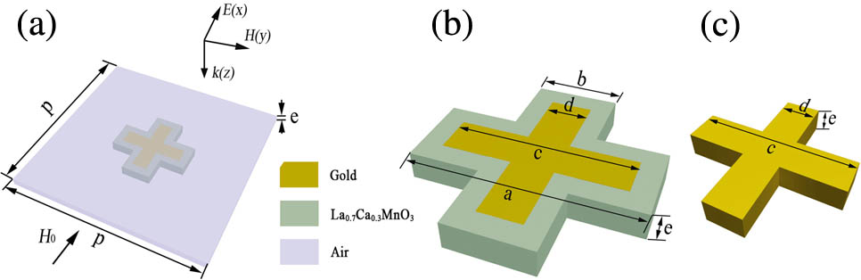
As shown in Fig. 1, the structure is periodic and centrosymmetric. In the center of each unit cell, there is a gold cross embedded in a CMR cross. The two crosses have the same thickness, and they are surrounded by air. Manganese oxide () is chosen as the CMR material because its resistance changes considerably with the increase in the external magnetic field, and because it can change even from a dielectric material into a conductor. Additionally, we easily obtained the exact parameters of the material that we used in the simulations from Ref. [56]. The detailed geometric dimensions are shown in the caption of Fig. 1. As shown in Fig. 1, a plane wave is normally incident to the structure, with its electric field parallel to the axis, and its magnetic field parallel to the axis. Since the structure is periodic, we only consider one unit cell with periodic boundary conditions in the simulations. Concretely, the two-paired surfaces of the unit cell in the two periodic arrangement directions are set to periodic boundary conditions, while the two surfaces of the unit cell in the propagation direction of the electromagnetic wave are set to ports. Additionally, the external magnetic field is applied along the direction. From the current distributions shown below, we can see that the directions of the currents are mainly along the axis. To ignore the impact of the magnetic force on the resonances[57], we make the direction of the external magnetic field the same as the ones of the currents. In order to obtain better results, the geometric sizes have been properly optimized.
Sign up for Chinese Optics Letters TOC. Get the latest issue of Chinese Optics Letters delivered right to you!Sign up now
Figure 1.(a) Schematic of a unit cell with centrosymmetric structure and the period . (b) Schematic of the cross, including the gold and in the unit cell, with the dimensions of , , , , and . (c) Schematic of the gold cross.
The simulations were performed using high frequency structure simulator software. The permittivity of the gold comes from the experimental data in Ref. [58]. The relationship between the resistivity of the material and the intensity of the external magnetic field acting on it can be extracted from Ref. [56], which can be approximately expressed aswhere is the resistivity of , is the intensity of the external magnetic field, is the related constant to . is the temperature, is the magnetization of , and is the initial intensity of the magnetization with . With Eq. (1) and the experimental data in Ref. [56], we can determine the range of the values and also retrieve for different and . As is well known, conductivity is the reciprocal of resistivity. It can be computed that the range of the conductivity values is from to . In this range, we employ five conductivities for the simulations: , , , , and . These values correspond to the values of 9 Oe and 26.5, 62.1, 63.8, and 65.1 kOe at , respectively. The occurrence of the CMR effects generally requires the excitation of a strong external magnetic field, while the magnetic field of the plane wave is much weaker than that of the former. We thus neglect the influence of the plane wave on the CMR effects. By analyzing a kind of magnetite material, it is found that the real parts of its permeabilities approach unity in the high-frequency range[59]. For simplicity, the permeability of is set to 1, and its magnetic loss is neglected in this Letter.
In the simulations, when the conductivity of the material is changed, the responses of the corresponding reflection coefficient and the transmission coefficient can be calculated directly. The absorption can also be yielded by , where denotes the reflection, and the transmission. As a result, the three physical quantities (i.e., reflection, transmission, and absorption) as functions of the frequency for different values can be obtained.
Figure 2 shows the simulation results for the different values of 9 Oe and 26.5, 62.1, 63.8, and 65.1 kOe. It can be seen from Figs. 2(a)–2(c) that when the is less than 26.5 kOe, the resonance frequencies of the structure are nearly unchanged. When the increases from 26.5 to 62.1 kOe, there is a 40 THz redshift, from 165 to 125 THz. As the value of further increases, the resonance position moves to the opposite direction, which means that the maximum tunable range is 40 THz. From the phase spectra in Fig. 2(d), we can clearly see that the phase is tuned at the resonance positions. The phase shift reaches a maximum of 0.5 rad at 145 THz, when the value of changes between 9 Oe and 65.1 kOe. From the above analyses, it is concluded that the resonance frequencies, as well as the transmission phases, can be actively tuned.
Figure 2.(a) Reflection, (b) transmission, (c) absorption, and (d) phase of the transmission coefficient as functions of the frequency for different values.
As we know the resonance frequencies of a resonator are closely related to its geometric size. A large size generally signifies lower resonance frequencies. Conversely, a small size produces a higher resonance frequency. When the sizes are the same, the resonance frequencies can also shift with the difference in the resonator’s components. In our designed resonator, the conductivity of the material increases by more than one order of magnitude when the intensity of the external magnetic field increases from a low value to a high one, such as from 9 Oe and 62.1 kOe. The resonance behaviors will therefore vary, and it is understood that the resonance can be tuned by the external magnetic field.
In order to more clearly understand the tunable process discussed above, we need to estimate the effective areas of the current oscillations that occurred in the resonator. Then, we use the effective oscillation areas to explain the physical mechanisms behind the tunable behaviors observed above. For this purpose, the current distributions in the gold and at the resonance frequencies for the three cases of 9 Oe, 62.1 and 65.1 kOe are drawn. The corresponding results are shown in Fig. 3.
Figure 3.Current distributions in the gold and at (a) 165, (b) 125, and (c) 150 THz corresponding to 9 Oe and 62.1 and 65.1 kOe, respectively. The areas surrounded by blue dotted lines are the concentrated values of the current oscillations.
From Figs. 3(a) and 3(b), we can see the currents mainly concentrate on the two central gold crosses. This is not surprising, because the gold is more conductive than the when has a relative lower value. However, the areas of the current distributions are different for the two cases, which means that the charges participating in the resonances are different when there is a change in the conductivity of . In contrast, the current shown in Fig. 3(c) is distributed over the whole area. This is because the conductivity of the material is comparable to that of gold for the 65.1 kOe magnetic field. We hence utilize different effective resonance areas to denote different resonances. The resonance areas are surrounded by the blue dotted lines, as shown in Fig. 3.
Following our work with the resonance areas, we construct three corresponding equivalent models: an equivalent narrow-crossing model (ENCM), an equivalent I-shaped model (EIM), and an equivalent wide-crossing model (EWCM). The models, which are made of gold, are shown in Fig. 4. The period of each unit cell is the same as that in Fig. 1(a). We simulate the three models and show the results in Fig. 5. From Fig. 5, we can see that the resonance frequencies are 165, 125, and 150 THz for the ENCM, EIM, and EWCM, respectively, which is in good agreement with those for the 9 Oe and 62.1 and 65.1 kOe curves shown in Fig. 2. However, their magnitudes at the resonance frequencies are greater than the curves in Fig. 2. This can be explained by the materials that the models and structures are made of: the resonance material in the equivalent models is gold, while in the aforementioned structures, the resonance material is the composite of gold and . The conductivity of is much lower than that of the gold. This implies that loss of is greater at the resonance positions. Consequently, the resonances generated in the structure shown in Fig. 1 are weaker than those in Fig. 4.
Figure 4.Schematics of the (a) ENCM, (b) EIM, and (c) EWCM corresponding to the areas marked by blue dotted lines shown in Figs. 3(a), 3(b), and 3(c), respectively. The material of the structures is gold.
Figure 5.(a) Reflection and (b) transmission as functions of the frequency corresponding to the three models in Figs. 4(a), 4(b), and 4(c), respectively.
In conclusion, we propose a new tunable resonator based on a CMR material. The simulation results show that the resonance frequencies are actively tuned over a range of 40 THz when the strong external magnetic field applied to the resonator is changed from 26.5 to 62.1 kOe. The simulation results also show that the resonator has a tunable capability in phase with a change of 0.5 rad when the external magnetic field varies from 9 Oe to 65.1 kOe. It is believed that such structures have potential applications in tunable nanophotonics devices.