A liquid crystal Pancharatnam–Berry (PB) axilens is proposed and fabricated via a digital micro-mirror-device-based photo-patterning system. The polarization-dependent device behaves as an axilens for a left-handed circularly polarized incident beam, for which an optical ring is focused with a long focal depth in the transverse direction at the output, and an anti-axilens for a right-handed circularly polarized incident beam, for which an optical ring gradually expands at the output. The modification of the size and the sharpness of the diffracted ring beam is demonstrated by encoding a positive (negative) PB lens term into the director expression of a PB (anti-)axicon.
Ring beams, sometimes also called annular beams or hollow beams, have been well studied due to their peculiar optical features for versatile applications. There are several possible ways of generating ring beams, e.g., using Laguerre–Gaussian (LG) modes with specific radial () and azimuthal () indices[1,2], making use of a spiral-phase embedded optical element[3–7], a light source passing through an axicon-based optical system[4,8–11], etc. Among these methods, an axicon that usually possesses long focal depth and high lateral resolution is effective to produce the ring-shaped beam; thus, it is one of the most prospective candidates for various applications, for instance, laser machining[9], laser surgery, and biomedical optics[8,12,13]. Indeed, an axicon can be used to generate a non-diffracting Bessel beam with the self-reconstruction property; hence, it has an advantage in the application of optical tweezers that can simultaneously trap spatially separated particles[14].
Conical-shaped axicons are conventionally made of optically isotropic materials, such as glass or fused silica[11,15]. Hitherto, researchers have proposed some methods of fabricating liquid crystal (LC) axicons via a computer-generated hologram[16,17], patterned electrodes[18,19], and photoaligning LCs to induce the Pancharatnam–Berry (PB) phase[20]. Distinct from the conventional LC amplitude or phase diffractive optical elements (DOEs)[21–29], highly efficient PB-phase optical elements (PBOEs)[30,31] with continuous space-variant optical axis distributions possess unique and interesting properties, among which the investigation on the superposition of multiple distinct PB phases is of great significance. Moreover, a single PBOE with the integrated PB phases provides the opportunity to facilitate the achievement of a compact and efficient optical system or device, thus leading to the low manufacture cost and low power consumption[32–34].
In this Letter, we propose a novel polarization sensitive LC Pancharatnam-Berry phase axilens (PBAL). The optical properties of the LC PBAL containing a null/positive/negative PB lens phase are individually investigated under left-handed circularly polarized (LCP) light and right-handed circularly polarized (RCP) light. In addition, the electro-optical (EO) behaviors of the proposed LC PBAL are studied. Due to the flexibility of the parameters’ choosing, a PB lens with an arbitrary focal length and a PB (anti-)axicon with an arbitrary pitch length can be encoded into the micro-patterned LC PBAL to facilely modulate the outgoing beam.
Sign up for Chinese Optics Letters TOC. Get the latest issue of Chinese Optics Letters delivered right to you!Sign up now
Normally, an LC PBOE is a half-wave plate that has its optical axis in the plane of the substrate with the azimuthal angle () spatially varying with respect to a fixed lab axis in a continuous manner[34]. The optical axis distribution of our proposed LC PBAL meets the condition αwhere denotes the radius from the center of the device, μ is the pitch length of the PB (anti-)axicon, is the designed wavelength, and is the focal length of the PB lens. We set the integer number in order to investigate the impact that is caused by the parabolic PB lens term. Given the Jones vector of the incident light , the electric field of the emergent light can be expressed via Jones matrix calculation: where the phase () changes continuously with .
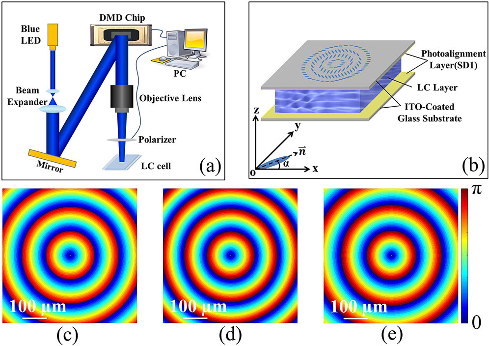
As shown in Fig. 1(a), the photo-patterning process is carried out by using a dynamic micro-lithography system with a digital micro-mirror device (DMD) chip (, pixel size μ) and a rotatable polarizer synchronously controlled by a computer[35]. A sulfonic azo-dye storage device [SD1, Dai-Nippon Ink and Chemicals, Japan (DIC), in N, N-dimethylformamide], which is sensitive to a polarized blue light-emitting diode (LED) ()[36], is spin-coated on two indium-tin-oxide (ITO)-coated glass substrates. The 1.8-μm-thick cell that is assembled with two treated glass substrates is then placed at the image plane of the photo-patterning system to record the designed patterns. The SD1 molecules in the exposed area tend to reorient their absorption oscillators perpendicular to the transmission axis of the polarizer, whereas those in the shaded area remain unchanged. After the eighteen-step exposure[37], the quasi-continuous space-variant director distribution for a PBAL is formed, and, thus, the director distributions of three different PBALs are arranged in the separated areas of the same cell. Thereafter, an LC SLC1717 (Yongsheng Huatsing Liquid Crystal Co., Ltd, China) with at a wavelength of 632.8 nm is infiltrated into the cell by capillary action. Eventually, three PBALs () are fabricated in the same LC cell with the configuration as shown in Fig. 1(b). In the Cartesian coordinates system, , the LC director at (, ), makes an azimuthal angle () with respect to the axis, and the probe beam () irradiates along -. The calculated director distributions for PBAL-I () that is equivalent to a PB (anti-)axicon, PBAL-II (), and PBAL-III () are correspondingly illustrated in Figs. 1(c)–1(e) with the variation of the gradient color from blue to red, indicating the variation of the director orientation from 0 to . Although the director distributions of the fabricated PBALs seem to have slight differences, their optical behaviors are obviously dissimilar. Because in our case, the PB (anti-)axicon phase term dominates in , thus, the PBALs mainly exhibit the characteristics of a PB (anti-)axicon. In principle, a tiny sharp ring beam at the focal plane can be obtained when the magnitude of the PB anti-axicon phase is much smaller than that of the positive PB lens phase, giving rise to an evident advantage for optical trapping.
Figure 1.Schematics of (a) the photo-patterning system and (b) the configuration of the LC PBAL and the designed director distributions for (c) PBAL-I (), (d) PBAL-II (), and (e) PBAL-III (). The white scale bars represent 100 μm.
The micrographs of the fabricated PBAL-I, PBAL-II, and PBAL-III under the polarizing optical microscope (POM) with two crossed polarizers are shown in Figs. 2(a)–2(c), respectively. The darkest areas in the figures indicate where the LC directors are parallel to the polarizer or analyzer, while the brightest areas show where the LC directors make an angle of with respect to the polarizer or analyzer. When the LC directors vary from 0 to , the dark-to-bright phenomenon emerges twice; hence, the fringe densities under the POM are higher, as compared with the corresponding phase profiles of PBAL-I, PBAL-II, and PBAL-III shown in Figs. 1(c)–1(e).
Figure 2.Micrographs of (a) PBAL-I (), (b) PBAL-II (), (c) PBAL-III () under the POM and (d) the experiment setup for characterizing the PBALs with identical aperture size (). The yellow scale bars represent 100 μm.
The experiment setup for characterizing the PBALs is depicted in Fig. 2(d). After the laser beam () passes through a beam expander, an aperture stop with a diameter of 1.2 mm is used to adjust the beam size to fit the size of the fabricated PBALs. LCP/RCP light is generated when the angle between the transmission axis of the polarizer and the axis of the quarter-wave plate (QWP) is . A flat screen is placed at a distance () from the LC sample to acquire the diffraction patterns, the images of which are captured by a digital camera Canon EOS 70D, and thus the outer diameter () of each diffracted beam at various distances can be facilely obtained.
The diagrams of the outer diameters of the laser beams () versus the distance () modulated by three different PBALs under LCP and RCP incident lights are plotted in Figs. 3(a) and 3(b), respectively. The insertions in both figures show the phase profiles (not to scale) associated with the optical axis distributions of , , and under the corresponding polarized light. In Fig. 3(a), after the LCP light beams transverse through the PBALs that almost satisfy the half-wave condition, their corresponding polarization state is changed to right-handed circular polarization. The diameters () of the light beams decrease first and then expand as increases from 12.5 to 87.5 mm. The diameters () are always smaller than the incident beam size in this region, thus showing the focusing effect as a result of the prominent feature of the axicon. In particular, PBAL-II exhibits an excellent focusing property at 62.5 mm, where the beam is converged to a tiny intense light spot [see Fig. 3(d)II]. The diameter () of the light beam for PBAL-I gradually enlarges, and the ring pattern shows up when further increases from 87.5 to 500 mm; hence, it coincides with the theoretical prediction that the focusing effect of PBAL-I (i.e., PB axicon) will end up at the distance due to the fact that each period of the concentric annular LC directors focuses the incident light to a corresponding focal distance with an identical convergent angle. Within the range, the beam size of PBAL-I is larger than that of PBAL-III but smaller than that of PBAL-II due to the reason that the added positive (negative) PB lens phase in working as a convex (concave) lens tends to expand (contract) the original beam size of a PB axicon that is identical to PBAL-I after a certain distance of the light propagation. The optical axis distributions of , , and under the RCP incident light exhibit the reversed phase profiles, as shown in the insertion of Fig. 3(b). PBAL-I becomes a PB anti-axicon with the defocusing property, while PBAL-II and PBAL-III perform as a PB anti-axicon in combination with a concave lens () and a convex lens (), respectively. Therefore, the versus curve for is located in between the curves for and [see Fig. 3(b)], and no focusing effect of the PBALs occurs.
Figure 3.Comparisons of the diffraction properties of the three PBALs. The diagrams of versus for three PBALs under (a) the LCP and (b) RCP incident lights. The insertions in (a) and (b) indicate the mutually reversed phase profiles for corresponding director distributions under different circularly polarized lights. The diffraction patterns for (c) PBAL-I (), (d) PBAL-II (), and (e) PBAL-III () under (I–V) LCP and (i–v) RCP incident lights at representative distances are shown.
The diffraction properties of the three PBALs are investigated visually via capturing the images of the diffraction patterns at representative distances, i.e., 12.5, 62.5, 87.5, 175, and 500 mm. In Figs. 3(c)–3(e), the figures labeled by uppercase Roman numerals (I–V) indicate that the LCP light at normal incidence is employed, while those marked by lowercase Roman numerals (i–v) mean that the RCP incident light is used. Under the LCP incident light, PBAL-II possesses the most concentrated energy distribution at 62.5 mm among the three PBALs, and it can generate an expanded and sharpened ring pattern [see Fig. 3(d)V] at 500 mm, whereas PBAL-III produces a contracted and blurred one [see Fig. 3(e)V] in contrast with the pattern in Fig. 3(c)V. Under the RCP incident light, the ring-shaped diffracted beams of the three PBALs appear at 12.5 mm and gradually expand with the increase of . Moreover, PBAL-III generates a smaller and sharper ring beam [see Fig. 3(e)v], while a larger and blurrier ring pattern for PBAL-II is observed [see Fig. 3(d)v], as compared with that for PBAL-I (i.e., PB anti-axicon) [see Fig. 3(c)v].
The EO properties of the PBALs are also studied. The voltage-dependent diffraction efficiencies () of the three PBALs are shown in Fig. 4. The solid curves represent the diffraction efficiencies under the LCP incident light, and the dashed curves stand for those under the RCP incident light. With the voltage rising from 0 to , the diffraction efficiencies of both solid and dashed curves climb to the peaks at around and then go all the way down to zero. The selected voltage-dependent diffraction patterns for PBAL-II under the LCP incident light at 500 mm are pointed to the corresponding points on the red solid curve. Note that the fabricated LC cell does not strictly meet the half-wave condition; specifically, the cell gap in our experiment is slightly larger than the ideal cell thickness of 1.6 μm. The zeroth order in the center of the ring pattern fades away when the electric voltage perfectly modulates the phase retardation; meanwhile, the diffraction efficiency reaches 97.3%. In addition, the EO response is tested by applying a signal at 1 kHz to the LC cell for 0.0125 s, followed by a null electric field lasting for 0.0125 s, alternately. The ON time () and OFF time () are measured to be 1 and 4 ms, respectively, according to the curve shown in the inset of Fig. 4.
Figure 4.Voltage-dependent diffraction efficiencies of the three PBALs under the LCP and RCP incident lights. The insertions show the EO performance and response of the fabricated LC cell.
In this work, an LC PBAL is proposed and fabricated by a dynamic photo-patterning system. With a quasi-continuous space-variant optical axis distribution, the polarization sensitive LC PBAL possessing an ultra-high diffraction efficiency up to is achieved. By encoding a proper PB lens phase into the phase expression of a PB (anti-)axicon, we can readily modify the size as well as the sharpness of the diffracted ring beam; furthermore, the light intensity distribution at the focal plane can also be adjusted. Owing to its advantageous optical properties, the proposed LC PBAL can definitely find prospective applications in optical manipulation, laser machining, biomedical optics, etc.