Min Li, Mingzhong Li, Zhenguo Wang, Xiongwei Yan, Jiangang Zheng, Xinying Jiang, Xiaomin Zhang. Theoretical modeling and experimental investigations of the effective thermal equilibrium time for Yb:YAG crystal[J]. Chinese Optics Letters, 2015, 13(Suppl.): S21412
Copy Citation Text
We propose a novel pulse amplification model to obtain the effective thermal equilibrium time () for Yb:YAG crystal, where has impacts on the gain recovery and energy extraction. A test amplifier is set up to measure the input fluence, output fluence, and pulse duration. By fitting the numerical values to the experimental data, the effective thermal equilibrium of Yb:YAG crystal at room temperature is found to be between 60 and 120 ps. To our best knowledge, this is the first time that an exact range of effective thermal equilibrium time for Yb:YAG is reported.
Yb:YAG is one of the most attractive gain media for high-energy (greater than the kilojoule level), high repetition rate () diode-pumped solid state lasers (DPSLLs), such as LIFE[1], HiPER[2] and Koyo-F[3]. Yb:YAG, as a gain medium, has advantages relative to Nd-doped phosphate glass. First, due to the longer storage lifetimes (), fewer diodes are required for Yb:YAG pumping. Besides, provides a lower quantum defect () and a higher emission cross section () at cryogenic temperature. Moreover, the YAG host material provides good thermo-mechanical and thermo-optical properties, and it can be produced in very large size in ceramic form[4–6]. Current high-energy Yb:YAG DPSSLs include DiPOLE with a pulse energy of 6.4 J at 10 Hz[7], Lucia with 14 J at 2 Hz[8], and GENBU with 1 J at 100 Hz[9].
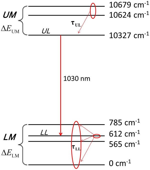
The simple two-energy levels of are split into sub-levels within the upper manifold (UM) and lower manifold (LM) by the Stark effect. Laser transition in Yb:YAG occurs at 1030 nm between the UM at upper laser level (ULL) and LM at the lower laser level (LLL) above the ground state, respectively, where ULL is the lowest-energy state in the UM[10]. In previous pulse amplification models, the basic assumption is that thermal equilibrium in the UM and LM is maintained at all times[11–13]. Some assumptions are based on the fact that the LLL of () is less than that of (), where the terminal-level lifetime of Nd-doped LG-750 is around ; consequently, the intuitive assumption is that the thermal equilibrium time (TET) for is much smaller than that of ions, and it has been ignored in these models[14]. However, the terminal-level lifetime can vary from picoseconds to microseconds with different laser host materials[15]. It is necessary to obtain the exact values of TET for the Yb ion, resulting in a more accurate modeling and prediction. For nanosecond pulse amplification, especially with high-energy () injection, the energy extraction and pulse shape distortion depends on the pulse duration with respect to the TET. If the pulse duration is much longer than the TET, then population in UM and LM will quickly return to the thermal equilibrium state (TES) during the passage of the pulse, and quasi-three-level operation will be obtained. However, in the case that the pulse duration is less than the TET, the LLL will become bottlenecked and the Yb-ion population will remain in the lower level during the passage of the pulse, resulting in effective two-level operation with reduced gain.
In this work, we propose a novel pulse amplification model to obtain an effective TET () for a precise modeling and prediction, where integrates the rates of the UM and LM returning to TES. Additionally, we set up a Yb:YAG test amplifier operating at room temperature to measure the input fluence, output fluence, and pulse duration. The best fitting results of the experimental data and numerical values show that is between 60 and 120 ps.
Sign up for Chinese Optics Letters TOC. Get the latest issue of Chinese Optics Letters delivered right to you!Sign up now
The TES in the UM and LM was broken by stimulated emission during the pulse passage. Because the thermal equilibrium recovery within the UM and LM can be described by the processes of ULL and LLL returning to the TES, respectively, then two parameters and are correspondingly introduced in our model to identify the rates of the processes, as shown in Fig. 1. The physics of and indicates the rate of the ULL receiving population from other sub-levels in the UM and the rate of the LLL draining population into other sub-levels in the LM for returning to the TES, respectively. The pulse amplification equations in Yb:YAG without considering the loss and the pump process can be written as where are the population densities in the UM and LM, is the total doping density, are the population densities in the ULL and LLL. Terms , , and represent the intrinsic atomic cross section, the photon energy, and the laser instantaneous intensity, respectively. The Boltzmann occupation factors within the UM and LM for the ULL and LLL of the laser transition are . The first terms on the right-hand side of Eqs. (1) and (2) describe population transformation between the ULL and LLL by stimulated transition, and the second terms indicate that population densities in the ULL and LLL return to the TES by rates of and , respectively.
Figure 1.Energy level structure of with the TET for the ULL and LLL.
In order to estimate the impact of the TETs on the population densities distribution within the UM and LM, we solve Eqs. (1) and (2) at a moment following stimulated transition under the assumption that the TES is maintained at the previous moment; then the analytical result of thermal population relaxation for ULL and LLL are where stands for the transformation population density caused by stimulated transition, and and are the population densities in the UM and LM, respectively, following the stimulated transition. The rate of thermal equilibrium is determined by and . Because the energy gap of the UM is less than that of LM (, , ), it is reasonable to consider that based on the energy gap laws. For at room temperature (, ), the coefficient for the population in ULL () is much smaller than that in LLL () and the difference will enlarge with temperature reduction. Based on the two facts, it can be inferred that the drain rate for population in the LLL mainly influences the TES recovery, and it is reasonable to attribute the thermal equilibrium process of the ULL to that of the LLL. Finally, the model is simplified by ignoring and introducing an effective TET to describe the TES recovery. Then the simplified equations for the model are
As mentioned previously, the LLL bottleneck becomes more clear while the laser system operates at cryogenic temperature for converging to unity and zero. Note that the intrinsic atomic cross section is adopted in the model instead of the effective emission and absorption cross sections.
In order to obtain the intrinsic atomic cross section, the reciprocity method is adopted in this work[16,17]. For the most simple case that the sub-levels in UM and LM are nondegenerate, and the transition cross section spectrum overlap between the sub-levels is negligible, the relationship for the intrinsic atomic cross section can be approximately expressed as where are effective emission and absorption cross sections, respectively. The value of the effective emission cross section used in this work is acquired from Ref. [18].
The test amplifier operating in an active mirror scheme at room temperature is shown in Fig. 2. The gain medium for the amplifier is a Yb:YAG disc with a doping concentrations 5 at. %, a thickness of 3 mm, and diameter of 35 mm. The Gaussian-shaped injection pulse with a duration of 12 ns (FWHM) and its near-field pattern with an area about are shown in Fig. 3. The pump beam is concentrated onto the front surface of the Yb:YAG disc with a top-hat profile of by vertical prisms and aluminum mirrors. The injection pulse beam passes through the center of the pump region for a uniform gain. The injection pulse energy is calculated by the product of the energy reflected by the thin slap (TS) and the reflectivity of the TS. The reflected energy and output energy are measured by energy detectors (EDs) 1 and 2, respectively.
Figure 4 shows the experimental output pulse fluence as function of the injection fluence [Fig. 4(a)] and the corresponding energy gain curves [Fig. 4(b)] at four different pump currents, where the energy gain is defined as the output fluence over the input fluence. It can be seen that the energy gain curves reflect the output energy increase more clearly with the pump power improvement compare to the output curves. The initial small energy gains for single V-shaped (double-pass) amplification are 1.73, 1.76, 1.79, and 1.83 at pump current of 170, 180, 190, and 200 A, respectively.
Figure 4.(a) Experimental pulse output fluence as function of the injection fluence and (b) corresponding energy gain curves.
In order to obtain the effective TET , simulations under numbers of ranging from 10 to 150 ps increase by 10 ps were fitted to the experimental data and the corresponding fluence fitting errors at each pump current were obtained. We took the time with the minimal fluence fitting error or at best-fitting as the effective TET. The fluence fitting error is defined as where the superscript “exp” and “num” represent the experimental output fluence and the corresponding numerical values at the same injection fluence, respectively; stands for the numbers of the experiment data at each pump current.
Figure 5 displays the fluence fitting error curves under the effective TET ranging from 10 to 150 ps and the energy gain curves at best-fitting with the experimental values under four pump currents. It can be seen that the effective TET are 60, 120, 80, and 60 ps and the corresponding minimal fluence fitting errors are about 0.23%, 0.35%, 0.31%, and 0.39% at pump currents of 170, 180, 190, and 200 A. The fluence fitting error curves reflect that indeed impacts on the pulse output fluence but not seriously under this condition. The reason that the effective TETs do not completely match between each pump current is mainly attributed to the pump power variation, which leads to the error of the initial energy gain for calculation. In spite of their incompatibility, the best-fitting results show that the effective TET is between 60 and 120 ps.
Figure 5.(a) Fluence fitting error curves; and (b) gain curves at minimal fluence fitting error. Both are with respect to pump currents of 170, 180, 190, and 200 A.
In conclusion, we propose a novel model to obtain the effective TET in Yb:YAG crystal for a precise modeling and prediction. A test amplifier operating at room temperature is built to measure the input, output and pulse duration. The numerical values is fit to the experimental output fluence under different and the time with the minimal fluence fitting error was taken as the effective TET. The results show that the effective TET for a Yb:YAG crystal at room temperature is between 60 to 120 ps, which is indeed smaller than the terminal time for ions about under this condition. Further efforts will be focused on the pump beam distribution and power improvement for a more uniform beam profile and higher stored energy. In order to estimate the effective TET more precisely, a test amplifier head operating at cryogenic conditions is currently under development.
Min Li, Mingzhong Li, Zhenguo Wang, Xiongwei Yan, Jiangang Zheng, Xinying Jiang, Xiaomin Zhang. Theoretical modeling and experimental investigations of the effective thermal equilibrium time for Yb:YAG crystal[J]. Chinese Optics Letters, 2015, 13(Suppl.): S21412