Dejing Gong, Yinquan Yuan, Lei Liang, Minghong Yang, "Theoretical study on negative permittivity of the material producing sharp surface plasmon resonance dips," Chin. Opt. Lett. 17, 042801 (2019)
Copy Citation Text
Using theoretical simulations for optical fiber surface plasmon resonance (SPR) sensors and prism-based SPR sensors coated with negative permittivity material (NPM), we investigated the effect of the permittivity of NPM on the transmitted spectrum of optical fiber SPR sensors and the reflected spectrum of prism-based SPR sensors and then obtained optimum permittivity of the NPM, which can excite the sharpest SPR spectrum in the white light region (400–900 nm).
Surface plasmon resonance (SPR) refers to the optical excitation of surface plasmon waves at the interface between a metal and a dielectric layer[1,2]. Till now, the most commonly used SPR sensors can mainly be divided into optical fiber SPR sensors[3–5] and prism-based SPR sensors[6–8]. For optical fiber SPR sensors and prism-based SPR sensors, the fiber core or the prism couples the incident light to the multilayer medium at the sensing probe. As the wavevector of incident light matches with the wavevector of the surface plasmon wave, the SPR spectrum shows a dip at the resonance wavelength or at the resonance angle. The SPR dip and its resonance wavelength or resonance angle are sensitive to the change in the refractive index (RI) of the surrounding medium. By measuring the shift of the resonance wavelength or resonance angle in the SPR dip, one can estimate the RI change near the sensor surface[1–8].
The natural metals that can produce the SPR phenomenon in the white light region (400–900 nm) are limited to several metals, such as gold (Au), silver (Ag), copper (Cu), aluminum (Al), and palladium (Pd)[9–12]. Au is often used because it has very stable optical and chemical properties. Ag is easily oxidized and has been greatly used after being protected by a protective layer. Cu, a much cheaper metal than both Au and Ag, can produce a good SPR signal and a better sensitivity, but it has the drawback of bad chemical stability in aqueous media. Therefore, Au films with the thickness of about 50 nm were often used in SPR sensors. But, the SPR spectra given by Au layers have great resonance dips, the full width at half-maximum (FWHM) is greater than 50 nm for common optical fiber SPR sensors, and the FWHM is about 2°–3° for typical prism-based SPR sensors, where such great resonance dips lead to a low signal-to-noise ratio and low detection accuracy of traditional SPR sensors. To improve the performance of SPR sensors, it is very necessary to know one kind of negative permittivity material (NPM) that can excite the sharp SPR spectrum in the white light region (400–900 nm).
Ishimaru et al. clarified the main characteristics of the SPR sensors based on the NPM and more generally metamaterials at microwave frequencies[13]. Plasmonic sensors based on metamaterials have been proposed for biosensing applications in the spectral ranges from visible light to the terahertz and microwave frequencies[14–19]. In this work, being inspired by the plasmonic sensors based on metamaterials, we try to introduce an NPM film into the optical fiber SPR sensor and prism-based SPR sensor by adjusting the permittivity of NPM film. We have investigated the effects of the permittivity of NPM film on the transmitted spectrum of an optical fiber SPR sensor and the reflected spectrum of a prism-based SPR sensor and then proposed the optimum parameters of the NPM film, which can produce a sharp SPR spectrum.
Sign up for Chinese Optics Letters TOC. Get the latest issue of Chinese Optics Letters delivered right to you!Sign up now
In the researches for SPR sensors, the most common method is based on a multilayer configuration consisting of a prism or fiber core, metal layer, sensing layer, and sample[4,20]. Using the Kretschmann structure and angular interrogation, the prism-based SPR sensor consists of a monochromatic light source, a photoelectric detector, a semi-circular prism, a reaction cell, two symmetrical actuating arms, and a microcomputer. To calculate the reflectivity of -polarized incident light (), multilayer models have been used to simulate the SPR sensors. The first layer is the prism or the fiber core made of fused silica with the RI of or , the second layer is the metal layer with thickness of , and its permittivity () can be expressed in a Lorentz–Drude model[21]: where is the light frequency, is the plasma frequency, is the plasma frequency associated with intraband transitions with oscillator strength and damping constant , while is the number of oscillators with frequency , strength , and lifetime . The third layer is the sensing layer with thickness , where the permittivity is given by . Sometimes, the SPR sensor is directly in contact with the sample, and such a sensor without sensing layers may be considered as a special case by setting . The fourth layer is the sample whose RI is denoted by .
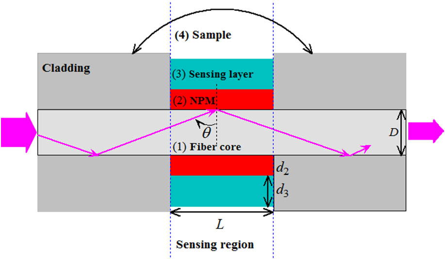
Figure 1 shows the optical fiber SPR sensor working in wavelength interrogation mode. The light from a collimated source is launched into one end of the optical fiber. The power arriving at another end of the optical fiber between the incident angles and can be written as[3,4]where is the RI of fiber core. Using the reflectance value for a single reflection at the core–metal interface, the normalized transmitted power of -polarized light will be
Figure 1.Configuration of optical fiber SPR sensors.
In Eqs. (3) and (4), represents the total number of light reflections performed by a ray making angle with the normal to the core–metal interface in the sensing region, and represent the length of the exposed sensing region and the fiber core diameter, respectively, is the critical angle of the fiber, whereas is the RI of the fiber cladding. Meanwhile, the polarization effect of different launched rays is neglected because the sensitive area is generally far from the input end of the optical fiber.
In Ref. [7], we are given the transmitted spectra of optical fiber SPR sensors with different metals according to Lorentz–Drude model and the Drude model; it was observed that the resonance curves corresponding to the metals of Au and Ag show obvious resonance dips in the wavelength range of 400–900 nm, and the Ag film can produce the best resonance dip. Even so, the optical fiber SPR spectra have large resonance dips, and the FWHM arrives at about 50 nm, which leads to a low signal-to-noise ratio and low detection accuracy. Taking Au as an example, Fig. 2 gives its real and imaginary parts of the permittivity according to the Lorentz–Drude model and the Drude model by squares and circles. It can be seen that their imaginary parts are slightly greater than zero, and their real parts are negative and decrease approximately linearly with the increasing of the wavelength in the white light region.
Figure 2.Permittivity of Au and NPM. Squares, Lorent–Drude model; circles, Drude model; solid, real part; open, imaginary part of the permittivity; solid, dash, dot, and dash dot lines are drawn according to , and the values of are 20, 25, 30, and 35, respectively.
Being inspired by the characteristic of the permittivity of Au and Ag, we suppose the existence of one kind of NPM, whose permittivity can be expressed as a simplest form: where three parameters of , , and are adjustable. In Fig. 2, the solid, dash, dot, and dash dot lines are drawn according to the formula of , and the values of are 20, 25, 30, and 35, respectively.
Based on the permittivity of the NPM layer, we simulated the transmitted spectra of optical fiber SPR sensors. Using an ordinary multimode silica optical fiber, without loss of generality, the parameters of , , , and were chosen, and the sample RI of was fixed in this section. By choosing the thicknesses and , Fig. 3(a) shows the normalized transmitted powers corresponding to different values of (0.05, 0.1, 0.15, and 2.0), where was fixed. As a reference, the normalized transmitted power corresponding to the Ag layer of 50 nm thickness and the Lorentz–Drude model was also given. It can be obtained that the SPR dip is very sharp, as is in the range of 0.10–0.15. Then, by fixing , Figs. 3(b) and 3(c) give the normalized transmitted powers corresponding to different values of (20, 25, 30, and 35) and (0.05, 0.06, 0.07, and 0.08), respectively; it can be observed that the optimized values of and are 20–25 and 0.06–0.08, respectively.
Figure 3.Normalized transmitted powers corresponding to different values of (a) , (b) , and (c) .
To understand the effects of the thickness of the NPM layer, without loss of generality, , , and were fixed, and the sensing layer was made of polyacrylamide with initial RI of ; we simulated the transmitted spectra for the different thicknesses of the NPM layer. Figure 4 gives the transmitted spectra when the thickness of the NPM layer equals 30, 40, 50, 60, and 80 nm, respectively, and it can be seen that, as the thickness of the NPM layer is less than 40 nm, the FWHM of the transmitted spectra is greater than about 30 nm; as the thickness of the NPM layer is greater than 80 nm, the minimum of the transmitted spectra is greater than about 0.60; and the resonance dips are sharper when is in the range of 40–60 nm.
Keeping the thickness of the NPM layer to be constant, three permittivities, , , and , were chosen; we simulated the transmitted spectra for the different RIs of the sensing layer. Figures 5(a)–5(c) give their normalized transmitted powers when the RI of the sensing layer is equal to 1.48, 1.46, 1.44, 1.42, and 1.40, respectively. It can be seen that the resonance dips produced by the NPM layer are obviously sharper than the normal SPR dip produced by noble metal; moreover, the variation of slope in can lead to a greater shift of the transmitted spectra, and the variation of imaginary part in has a greater effect on the FWHM and minimum of the transmitted spectra.
Figure 5.Transmitted spectra for the sensing layers with different RIs.
Progressively, Fig. 6(a) gives the resonance wavelengths corresponding to different values of that can be obtained and expressed as where represents the initial RI of the sensing layer, , , and for the NPM1 layer; , , and for the NPM2 layer; , , and for the NPM3 layer. Figure 6(b) gives the FWHMs of the transmitted spectra corresponding to different values of . It can be observed that, although the sensitivity of the optical fiber SPR sensors coated with NPM1 is slightly greater than the sensitivities of the SPR sensors coated with NPM2 and NPM3, the FWHM of the optical fiber sensor coated with NPM3 (5.44–8.83 nm) is obviously lower than the FWHMs of the SPR sensors coated with NPM1 (9.28–14.12 nm) and NPM2 (8.88–14.50 nm), so an optimum NPM layer with the dielectric function of may be obtained.
Figure 6.(a) Resonance wavelengths and (b) FWHMs of optical fiber SPR sensors coated with NPM1, NPM2, and NPM3.
For optical fiber SPR sensors, the incident light lies between its critical angle in the optical fiber (typically about 84°) and 90°, so the optimum permittivity of the NPM layer on the optical fiber SPR sensor, , was proposed. But, for prism-based SPR sensors with angle interrogation, the wavelength of monochromatic light may be chosen in the range of 400–900 nm, the incident angle can be changed in the range of 40°–90°, so the optimum parameters of the NPM layer coated on the prism-based SPR sensors also need investigation.
In this section, the RIs of and and the thickness of were fixed. Based on Eq. (5), we have simulated the effect of the thickness of the NPM layer on the reflected spectrum of the prism-based SPR sensor. Figures 7(a)–7(c) show the reflectivity corresponding to different values of , where is fixed. It can be obtained that the resonance angle increases from about 56° to 61° when the wavelength of monochromatic light decreases from 900 to 550 nm, the SPR dip is sharp, and the dip reflectivity is low, as is in the range of 40–60 nm, so the 50 nm thickness of the NPM layer was fixed in the following.
Figure 7.Dependence of reflectivity on the wavelength and incident angle for different thicknesses of NPM layers.
We simulated the reflected spectra of the prism-based SPR sensors with different parameters of dielectric function of the NPM layer. The thicknesses of and and the wavelength of were fixed. Figure 8(a) shows the reflectivity corresponding to different values of (0.10, 0.50, 1.00, and 1.50), where was fixed; It can be obtained that the SPR dip is sharp as is in the range of 0.50–1.50. Fixing , when the dip reflectivity is close to 0, Figs. 8(b) and 8(c) give, respectively, the reflectivity corresponding to different values of (20, 25, 30, and 35) and (0.05, 0.06, 0.07, and 0.08); it can be observed that the acceptable values of and are 20–25 and 0.06–0.08, respectively.
Figure 8.Reflected spectra of prism-based SPR sensors corresponding to different values of (a) , (b) , and (c) .
Using the NPM layers with the permittivities of , , and , we have simulated the reflected spectra for different sample RIs. Figures 9(a)–9(c) give their reflectivity of prism-based SPR sensors when the sample RI is equal to 1.33, 1.34, 1.36, 1.38, and 1.40, respectively. It can be seen that their resonance dips are obviously sharper than the normal SPR dips given by noble metals. Progressively, Figs. 10(a) and 10(b) give the sensitivities and FWHMs of these SPR sensors, and the resonance angles corresponding to different can be expressed as where , 71.729, and 70.330 (°)/RIU represent the RI sensitivity of prism-based SPR sensors coated with NPM1, NPM2, and NPM3, respectively. Although the sensitivity of the prism SPR sensors coated with NPM1 is slightly greater than the sensitivities of the prism SPR sensors coated with NPM2 and NPM3, the FWHMs of the prism SPR sensors coated with NPM2 and NPM3 (0.217°–0.308°, 0.143°–0.205°) are obviously lower than the FWHM of the prism SPR sensors coated with NPM1 (0.683°–0.950°), so the optimum NPM layer with the permittivity of may be obtained.
Figure 9.Reflected spectra of prism-based SPR sensors coated with (a) NPM1, (b) NPM2, and (c) NPM3.
In conclusion, one kind of NPM, which can produce a sharp SPR spectrum in the white light region (400–900 nm), was applied to two kinds of SPR sensors. Based on the simulations for an optical fiber SPR sensor and prism-based SPR sensor coated with the NPM, the effects of the permittivity of NPM on their transmitted spectrum or reflected spectrum have been investigated. For the optical fiber SPR sensor with an NPM layer, the optimum permittivity of the NPM may be obtained, correspondingly, where the FWHM is less than 8.83 nm, and the RI sensitivity is about 1357.772 nm/RIU when the RI of the sensing layer changes from 1.40 to 1.48. For the prism-based SPR sensor coated with an NPM layer, the optimum permittivity of the NPM may be obtained, correspondingly, where the FWHM is less than 0.205°, and the RI sensitivity is 70.330 (°)/RIU when the sample RI changes from 1.33 to 1.40.
Dejing Gong, Yinquan Yuan, Lei Liang, Minghong Yang, "Theoretical study on negative permittivity of the material producing sharp surface plasmon resonance dips," Chin. Opt. Lett. 17, 042801 (2019)