
Tan Yang, Ying Song, Wentao Zhang, Fang Li. Acoustic emission detection using intensity-modulated DFB fiber laser sensor[J]. Chinese Optics Letters, 2016, 14(12): 120602
- Chinese Optics Letters
- Vol. 14, Issue 12, 120602 (2016)
Abstract
The acoustic emission (AE) technique as a kind of new nondestructive testing technology has a broad potential application in the field of nondestructive testing. Traditional AE sensors are usually made of piezoelectric (PZT) ceramic materials, which are not only susceptible to electromagnetic interference, but also unsuitable for being embedded into structures. Fiber optic sensors have considerable advantages over traditional PZT sensors, such as a small diameter, light weight, flexibility, immunity to electromagnetic interference, durability, ease of installation and multiplexing, and a simultaneous measurement of temperature and strain[
In this Letter, we present the bonded intensity response of the DFB-FL to the external AE signal, and the acoustic measurement based on the AE is done on an aluminum plate to prove the feasibility of the sensing scheme. We reveal the sensitivity response curve of the intensity-type DFB-FL sensor to external AE signals and explain the minimum of the stress wave that can be detected by the method.
First, we explain the focus of this Letter, which is to use the intensity characteristics of the DFB-FL as the receiver of the AE signal. When there is external AE signal applied on the phase-shift grating, the fiber is physically stressed due to the elasticity of the fiber, and the refractive index of the fiber is modified because of the photo-elasticity[
Sign up for Chinese Optics Letters TOC. Get the latest issue of Chinese Optics Letters delivered right to you!Sign up now
Therefore, the grating coupling coefficient and the refractive index of the FL influences its output power. As a result, the effect of the external AE signal modulation, which may contribute significantly to the DFB-FL’s intensity, should be analyzed and discussed.
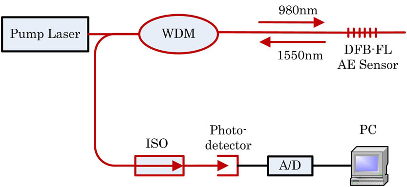
As shown in Fig.
![]()
Figure 1.Intensity FL AE sensing scheme. ISO, isolator.
The intensity characteristics of the DFB-FL include the relative intensity noise (RIN) of the output laser and the intensity response characteristics of the external pressure excitation. The characteristic of RIN plays an important role in the sensitivity of the sensor. The length and refractive index of the fiber grating can be changed when the external AE is excited in the DFB-FL, which can cause the fluctuation of the output power of the DFB-FL. Finally, the RIN spectrum is obtained by the software program in the computer. The RIN is given by
The DFB-FL has excellent sensing properties, such as anti-electromagnetic infection, high temperature resistance, ease of wavelength division multiplexing, and so on. But, its own structure is thin and easy to break. This Letter designs a kind of bonded sensor to protect the FL, as shown in Fig.
![]()
Figure 2.(a) Structure of the bonded DFB-FL sensor. (b) Bonded DFB-FL AE sensor.
In order to investigate the intensity response of the DFB-FL to AE signal, first, the relative noise of the system is evaluated, and then by comparing that with the PZT sensor, the sensitivity curve of the test band is obtained. Finally, the burst signal by the DFB-FL AE sensor is aquired.
The experiment of AE sensitivity calibration is carried out on a square aluminum plate, as shown in Fig.
![]()
Figure 3.Detection of AE waves in an aluminum plate.
A 5.1 kHz sinusoidal signal is generated by a signal generator and collected by the DFB-FL AE sensor and the PZT receiver. The AE sensitivity of the PZT receiver is expressed as Eq. (
Figure
![]()
Figure 4.(a) Frequency domain characteristics of the 5 kHz Signal. (b) Time domain characteristics of the 5 kHz AE signal.
The sensitivity of the DFB-FL AE sensor is calibrated by comparing the received signals of the PZT AE sensor and the DFB-FL AE sensor when the AE generator is driven by a specific voltage. The sensitivity of the DFB-FL AE sensor is expressed as
By testing the AE waves at different frequency points, the frequency response of the DFB-FL AE sensor is obtained, which is shown in Fig.
![]()
Figure 5.Sensitivity response curve of the intensity-type DFB-FL sensor to external AE.
Then, the AE sensitivity at 5.1 kHz can be calculated as 17.96 dB re mW/m/s. The decibels (dB) in Fig.
In addition, the sensor will be used to detect the AE signals of rock mass in a future work. The rock AE signal is mainly at a low frequency. Finally, we use the shocked steel ball method to simulate the burst AE signal. In the experiment, the burst type AE signal generated by the shocked steel ball is transmitted to the DFB-FL AE sensor and the PZT receiver through the surface of the aluminum plate. Figures
![]()
Figure 6.(a) Signal of a shocked steel ball by the PZT sensor, (b) Signal of a shocked steel ball by the bonded DFB-FL sensor.
In order to show the frequency of the signal acquisition, we have carried out the fast Fourier transform, as shown in Fig.
![]()
Figure 7.Fast Fourier transform of the signal.
In conclusion, we present our recent work on the DFB-FL-based AE sensor. With the intensity modulated type FL sensor, we obtain a high frequency response AE detection system with the benefits of simplicity in demodulation and multiplexing. The minimum detectable signal is tested to be better than
References
[1] W. Z. Huang, H. X. Ma, W. T. Zhang, F. Li, Y. L. Du. Advanced Sensor Systems and Applications V(2012).
[2] P. Finkel, R. Miller, R. D. Finlayson, J. Borinski. AIP Conf. Proc., 557, 1844(2001).
[5] W. He, L. Cheng, Q. Yuan, Y. Liang, L. Jin, B.-O. Guan. Chin. Opt. Lett., 13, 050602(2015).
[7] G. M. H. F. Geoffrey, A. Cranch, C. K. Kirkendall. IEEE Sens. J., 8, 1161(2008).
[8] W. Z. Huang, W. T. Zhang, F. Li. Sensors, 13, 14041(2013).
[10] Q. Wu, Y. Okabe. Opt. Express, 20, 28353(2012).
[11] D. J. Hill, B. Hodder, J. De Freitas, S. D. Thomas, L. Hickey. 17th International Conference on Optical Fibre Sensors, Pts 1 and 2, 904(2005).
[12] W. Z. Huang, W. T. Zhang, H. X. Ma, F. Li, Y. L. Du. Appl. Mech. Mater., 330, 412(2013).
[13] J. Z. Zhang, X. L. Li, Q. A. Chai, Q. Q. Hao, Q. Li, W. M. Sun, L. B. Yuan, P. Lu, G. D. Peng. 2010 IEEE Sensors, 315(2010).
[14] N. Takahashi, K. Yoshimura, S. Takahashi, K. Imamura. Ultrasonics, 38, 581(2000).

Set citation alerts for the article
Please enter your email address
© Copyright 2018-2021 | Chinese Laser Press. All Rights Reserved 沪ICP备15018463号-20