Collinear phase-matching of sum-frequency generation (SFG) has been studied thoroughly previously, while non-collinear schemes are sometimes more flexible in application. However, this phase-matching type is more difficult to meet and control. We employ a convenient method to obtain harmonic generation in bulk potassium dihydrogen phosphate (KDP), using an incident wave vector and a reflected wave vector to create a triangle phase-matching relationship. With a simple, flexible set-up, we can observe 351 nm SFG, and the conversion efficiency is up to ~3.6% per reflection. Furthermore, we believe this approach has potential application value and improvement space.
Phase-matching plays a very important role in nonlinear frequency conversion. To improve the conversion efficiency, ensuring complete phase-matching () is essential. Collinear phase-matching is the most common pattern in our practical application, whose vector condition can be written as the scalar form [1]. From this equation, we see that the dispersion characteristic of the medium is the key of phase-matching. When it comes to a non-collinear pattern, the angles between those wave vectors should be taken into account. Traditional frequency conversion methods, as are well known, are birefringence phase-matching (BPM) and quasi-phase-matching (QPM). The former takes advantage of the birefringence property in crystal, which is usable in both collinear phase-matching and the non-collinear one. The latter brings an extra reciprocal lattice vector to compensate the phase mismatch , as Bloembergen et al. proposed in Ref. [2].
Besides, some interesting new types of phase-matching schemes have also attracted much attention in recent years. For example, nonlinear Bragg diffraction (laterally adding several reciprocal lattice vectors to the triangular phase-matching scheme)[3,4], nonlinear Raman–Nath diffraction (automatically lateral phase matched)[5,6], nonlinear Cherenkov radiation (automatically longitudinal phase matched)[7–10], and some conical harmonic generation in isotropic material[11], random-domain crystal[12], photonic crystal[13,14], or bulk crystal[15]. As for conical harmonic generation, the scattering lights towards every direction inside the materials often contribute a wave vector in the phase-matching scheme. Due to the existence of large quantities of scattering lights, we could observe circular or semi-annular harmonic generation.
In Ref. [15], a handy method is reported to organize a triangular complete phase-matching scheme. Based on the total reflection at the crystal boundary, using reflected light to replace the role of scattering light significantly enhances the output second harmonic generation (SHG). Of course, unlike scattering light, this reflection-assisted phase-matching is much more sensitive to the incident angle. That is, there will be a critical SHG enhanced point instead of easily formed SHG rings during rotating the crystal. The conversion efficiency of a single reflection is quite appreciable, up to 14.8%. This type of frequency conversion shows potential in micro-structural devices.
Sign up for Chinese Optics Letters TOC. Get the latest issue of Chinese Optics Letters delivered right to you!Sign up now
Moreover, we focus on harmonic generation in the ultraviolet band. As we know, ultraviolet light attracts extensive research interests for its value in many areas, such as micromachining, medicine, semiconductor processing, and optical communications[16]. However, the deeper the ultraviolet light we want, the higher the order of nonlinear process it requires in frequency up-conversion, which means more difficulties in practical operation.
We consider a sum-frequency generation (SFG) conversion process employing a 1053 nm laser source. This process is associated with a fundamental wave (FW) beam and an SHG beam. In potassium dihydrogen phosphate (KDP) crystal, the phase-matching scheme will be like a triangle according to the values of these three wave vectors, but this non-collinear sum frequency is experimentally inconvenient to conduct. Thus, we exploit total reflection at the crystal inner surface to make the adjustment easier.
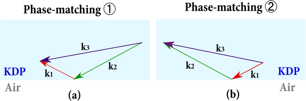
If we simultaneously shoot both FW and SHG beams into the bulk KDP along the same path and approximately neglect the small displacement between two beams, then, as shown in Fig. 1, there could be two possible phase-matching schemes.
Figure 1.(a) Scheme of SFG phase-matching exploiting reflected FW and incident SHG. (b) Scheme of SFG phase-matching exploiting incident FW and reflected SHG.
All incident and reflected lights are taken into account in Fig. 1. However, theoretically, the second case in Fig. 1(a) could not be observed in the experiment because of the total reflection of SFG at the crystal inner surface.
In our experiment, the KDP crystal is cut with dimension of , as shown in Fig. 2(a). The main set-up is given by Fig. 2(b). The FW (1053 nm) comes from a neodymium-doped yttrium lithium fluoride (Nd:YLF) picosecond laser (50 ps, 1 Hz, at far right). We use a lithium triborate (LBO) crystal (a cube about 1 cm on a side) for SHG (526.5 nm) from the FW; hence, both SHG and the FW shoot into KDP in the same direction. KDP is put on a rotation stage so that the incident angle can be continuously adjusted. The FW and SHG would experience a reflection at the crystal inner surface, where the overlapping area of incident and reflected light is supposed to emit SFG at a critical angle. Besides, in order to observe and measure SFG, a light filter is put behind the KDP to separate the high-power infrared FW and the glaring green SHG off. On the paper screen, ultraviolet light will excite blue fluorescence at the spot positions, making the phenomena directly seen by eyes.
Figure 2.(a) Schematic of the KDP sample. (b) Schematic of the main experimental set-up.
In our calculation, we employ ooe-type phase-matching to get SFG. The laser in our set-up emits horizontally-polarized FW, which is e-polarized for the KDP crystal. Therefore, a half-wave plate is needed in front of LBO to turn a part of the original FW into an o-polarized (vertically-polarized) state. For the double-frequency process in LBO, the incident FW is supposed to be horizontally-polarized, while the output SHG is supposed to be vertically-polarized. The trade-off between the conversion efficiency of SHG in LBO and the effective FW (o-polarized FW) for SFG conversion process will be discussed later.
We also discuss if the SHG process in LBO will make some delay between the input FW and output SHG, so we analyze the walk-off in LBO. This SHG process is a collinear ooe-type process, and the LBO is designed to work under the condition of normal incidence. Hence, when the phase-matching condition is satisfied, the velocities of the FW and SHG will be the same; that is, the pulses of the horizontally-polarized FW and the vertically-polarized SHG in LBO are still synced pulses
During the experiment, we find that both phase-matching schemes [Figs. 1(a) and 1(b)] can be observed with corresponding phenomena; that is, we find two SFG light spots on the screen that are symmetric on the reflecting surface of the KDP crystal. We have already predicted that only the spot at the side of the reflection direction could be observed, like the phenomenon diagram on the paper screen in Fig. 2(b); however, if the diameter of the laser beam is relatively large, then there will be a part of output SFG missing in the total reflection process at the inner surface, as in Fig. 3.
In Fig. 3, we notice that the incident lights are not reflected completely. The shadow area represents the overlap area, where the phase-matching scheme is presented in Fig. 1(a), so the second type of phase-matching scheme can be verified as well experimentally.
Figure 3.Diagram of KDP interior, indicating the interaction range of reflected FW and incident SHG.
Figure 4 displays the phenomenon and corresponding theoretical interpretation in our experiment. In Fig. 4(a), the photo bar shows the phenomena observed in the experiment when the incident angle of the FW and SHG comes to around 15°. There are five spots on the paper screen. The farthest two spots on both sides are transmitted and reflected FW and SHG spots. The middle spot is on the extension of the crystal reflecting surface, and the two blue spots are the SFGs we expect to study. To observe the evolution process of approaching the phase-matching point, we put a filter behind KDP and rotate the stage, as shown by the two round photos in the Fig. 4(a). Figure 4(b) explains this process with the opinion of the geometrical relationship of wave vectors. Under the phase-mismatching condition [left photo in Fig. 4(a) and left scheme in Fig. 4(b)], we can see two blue rings of different radii at both sides symmetrically. These rings arise from the scattering-light-assisted sum-frequency process, as we mentioned in the second paragraph. When the incident angle of the FW and SHG meets the phase-matching point [right photo in Fig. 4(a) and right scheme in Fig. 4(b)], the blue scattering-assisted SFG rings are precisely tangent to each other, and two bright SFG spots can be observed as well as probed at the location of the tangent point. Obviously, reflected light is much stronger than scattering light, and thus the enhancement of SFG at the phase-matching point is remarkable. As for these two SFG spots in the photos, the left spot [corresponding to Fig. 1(a)] is weaker than the right spot [corresponding to Fig. 1(b)], because the overlapping volume (interaction region) of phase-matching ① is apparently smaller than that of phase-matching ②.
Figure 4.(a) Photograph of the screen in the SFG experiment, where the lower two small round pictures show the process from phase-mismatching to phase-matching. (b) The phase-matching diagram of the process in (a), showing the scheme of scattering-assisted conical SFG as well as the reflection-assisted SFG.
Combining reflection law, refraction law, and the Sellmeier equation, we can calculate the exact phase-matching angles at any certain FW wavelength. One approximate assumption we made to simplify our analysis is that the FW and SHG share the same optical path during the whole propagation. As Fig. 5(a) shows, we define several important angles in our measurement. is the external incident angle of the FW light and SHG light, is the internal incident angle of them, is the external emergent angle of the SFG light, and is the internal emergent angle of it. In this ooe-type phase-matching scheme, the relationship of those angles and refractive indices is associated mutually, which is shown as the following equations: where and are refractive indices of o-polarized FW and SHG in KDP crystal, respectively, and is the refractive index of e-polarized SFG in KDP, varying with the incident angle.
Figure 5.(a) Diagram of comprehensive, simplified reflection and refraction processes at boundaries of KDP, and the triangular phase-matching of SFG. (b) The prediction curves of the SFG critical angles at the phase-matching point for the FW wavelength from 800 to 1500 nm. The red line shows the results at the wavelength we use.
Through solving Eqs. (1)–(4), we can precisely predict a series of phase-matching angles at any certain wavelength of the FW. The critical angles in a range of wavelengths in our calculation are presented in Fig. 5(b). Basically, the external incident angle of the FW and SHG and emergent angle of SFG measured in our experiment are within expectation.
Except for verifying the critical phase-matching data, we conducted some further measurements in our experiment. In the following statement, all the powers we mention in the figures refer to peak power. Besides, we have adjusted the reflecting location at the KDP inner surface to make the FW and SHG completely reflected; thus, only phase-matching ② in Fig. 1(b) happens (the SFG spot only appears at the reflecting side).
First of all, the whole experimental set-up we employ is quite simple and easy-to-use, while some sacrifice has to be made. The LBO we use is a collinear frequency doubling crystal, requiring a horizontally-polarized incident FW component and delivering vertically-polarized emergent SHG; the more the horizontally-polarized FW component participates, the stronger the SHG that comes out. For SFG, the SHG is already o-polarized for KDP, but the original FW needs to pass a half-wave plate to provide an e-polarized component. Therefore, we should consider the balance in the energy allocation of the FW and SHG. From Fig. 6, we know that there is an output peak between two extreme cases: complete vertically-polarized FW and complete horizontally-polarized FW. This peak is around the middle position, which means that when the components of the horizontally-polarized and vertically-polarized FW share approximately equal energy, we can obtain efficient light output. Although in the current set-up trade-off remains, it potentially solves the contradiction by improving the frequency-doubling part. Hence, this set-up is still a good choice for its convenience and flexibility.
Figure 6.Regular variation of output power with the rotation of the half-wave plate.
Theoretically, we can derive the expression of output power from the coupled wave equation.
For SFG, we assume slowly varying amplitude approximation on the FW and SHG; then, the intensity of third harmonic generation (THG) can be written as so the power of THG is expressed as
Moreover, we infer the expressions of according to the triangle phase-matching scheme in Fig. 5(a) as
Using Eqs. (7) and (1)–(3) that we mentioned before, we can plot the theoretical relationship curve between the incident angle of the FW (SHG) and output power of SFG. We measured the output powers in a small range of incident angles around the phase-matching point in SFG. In Fig. 7, the blue stars represent experimental data, and we fit them using spline interpolation to portray a peak profile; the purple dashed line is the ideal profile derived from Eqs. (1)–(3) and (7), whose dissymmetry is not apparent and looks fairly like sinc functions. The experimental data and fitting curve seem distorted mainly because of the unstable input of the laser at a high power level, so that each pulse has small difference in energy. Besides, the deviation of the peak position is probably from the methods in our measurement, especially in the SHG experiment, where the error in judging the beginning of the rotation will significantly affect the measurement of such a small angle.
Figure 7.Output power in the SFG experiment as a function of the external incident angle (). This group of data is measured when the incident average power (sum of FW and SHG powers before shooting into KDP) is 4.38 mW.
We studied how the powers of incident lights affect the output power of SFG experimentally as well. As Fig. 8 shows, we classify the experimental data based on the power proportion of two incident lights. The values of are 0.86, 0.66, and 0.43, respectively. According to Eq. (6), we know ∝ at a fixed incident angle. This conclusion means the value of will not make a difference when SHG is still strong. The linear fitting curves of our experimental data in Fig. 8 quite agree with this conclusion. The curves of and are very close to each other, while the slope of the curve is a little different from them.
Figure 8.Output power in the SFG experiment as a function of the product of FW and SHG powers.
On the other hand, we figure out the maximum of conversion efficiency among all the experiments above.
For SFG, the maximum of conversion efficiency is when total incident average power is 4.38 mW. The conversion efficiency is obtained through dividing 4.38 mW by the average power of the SFG spot measured behind KDP. According to Fig. 7, the maximum conversion efficiency corresponds to the external incident angle at 15.09°.
The diameter of the laser is about 7 mm. Through the geometrical method, we evaluate the volume of the overlapping region: first, we treat the shape of the beams inside KDP as a cylinder; we figure out the internal incident angle of the FW and SHG at the phase-matching point so that we can image the general outline of the overlapping region, which is a symmetric geometry enveloped by two cylinders and a plane; then, we use the mathematical way to solve this problem. In our calculation, the overlapping volume is about .
In Ref. [15], the sample is 5% (mole fraction) crystal, whose nonlinear susceptibility is much larger than that of the KDP crystal we use. When employing 5% and a femtosecond pulse source, a conversion efficiency of 7.9% at 1480 nm (FW) by one reflection can be obtained when the total input is 2.14 mW[17]. We make a comparison of second-order nonlinear coefficients between and KDP as the following [according to nonlinear crystal calculation software (SNLO)]:
Usually, we prefer crystals with larger second-order nonlinear coefficients, but the applicable band of MgO:LN is 0.4–5.5 μm[18]. Therefore, for SFG at a shorter wavelength, such as the ultraviolet band, MgO:LN is not a good choice. If other crystals with larger are exploited, we have full confidence in obtaining higher conversion efficiency.
Therefore, generally, the conversion efficiency is relatively high considering the small scale of the overlapping region. Though a single reflection provides only a small amount of SFG, it is possible to strengthen the output light by further means. Managing to generate coherent enhanced output light through multiple reflections, for example, is a hopeful alternative.
Moreover, this kind of non-collinear phase-matching SFG owns its unique advantage among a variety of phase-matching methods. As for normal collinear phase-matching exploiting birefringence in crystals, the inherent walk-off effect also results in the separation of input and output lights. While for the type of SFG in our method, though a single reflection only forms a short active length, it is quite possible to design a multiple-reflection structure to enlarge the overlapping region and further enhance the output SFG. QPM is commonly used, too. However, a special domain structure to introduce a reciprocal lattice vector is required, for example, periodically poled lithium niobate (PPLN), and the added preparation process raises extra cost and technological issues in the application. When it comes to general non-collinear phase-matching, finding the exact phase-matching angles in actual operation is usually difficult and complicated. But, our experiment illustrates a fewer-variables adjustment process. It would be easier to capture the expected SFG than the normal non-collinear phase-matching design.
In summary, through the mechanism of reflection-assisted triangular phase-matching, we can observe SFG (351 nm) with the FW (1053 nm, in the infrared band) and SHG (526.5 nm) sharing a common incident path. The complete phase-matching condition and relatively strong reflected light enhance the output lights. The conversion efficiency of 351 nm light is . The significant output under the condition of such a small overlapping region and nonlinear susceptibility of KDP implies that this type of harmonic generation has potential as an efficient non-collinear process. More exquisite designs should be tried in further study, so as to fully utilize the high conversion efficiency of a single reflection and the flexibility of an experimental set-up.
[4] S. M. Saltiel, D. N. Neshev, W. Krolikowski, R. Fischer, A. Arie, Y. S. Kivshar. Proc. SPIE , 6801, 680113(2008).
[5] S. M. Saltiel, D. Neshev, W. Krolikowski, A. Arie, N. Voloch, O. Bang, Y. S. Kivshar. European Conference on Lasers and Electro-Optics 2009 and the European Quantum Electronics Conference., 1(2009).
[6] H. Liu, J. Li, X. Zhao, Y. Zheng, X. Chen. CLEO: Applications and Technology, JTu5A.65(2017).