Abstract
In an experiment on the round-trip fiber transfer of joint frequency and time signals based on wavelength-division multiplexing technology, a specific bidirectional erbium-doped fiber amplifier (Bi-EDFA) with low noise and high symmetry simultaneously is designed and applied to compensate for the loss of the link. The Allan deviation (ADEV) deterioration of the 1 GHz frequency signal induced by the Bi-EDFA is only at 1 s and at in the forward direction, and is at 1 s and at in the backward direction. The degraded time deviation (TDEV) caused by the asymmetry of the Bi-EDFA is only 0.8 ps at an average time of . With the proposed Bi-EDFA, in the field experiment on the 110 km fiber transfer of joint frequency and time signals, the ADEV of the 1 GHz frequency signal is at 1 s and at . The TDEV of the 1 pulse per second time signal is 6.8 ps with an average time of The remote transfer of ultra-stable frequency and time standards is of great importance in many areas. Due to the rapid development in the stability of frequency and time standards[1,2], the widely used methods based on a satellite link will no longer satisfy the high requirements[3]. Nowadays, exploiting optical fibers for such a transfer presents a much better performance[4–6].
Signal regeneration must be considered when the total loss along the fiber link is large enough that the signal cannot be detected by the photo detector at the remote end. Owing to its direct optical amplification, erbium-doped fiber amplifiers (EDFAs) are widely used in optical fiber transmission systems[7,8]. However, in a round-trip fiber transfer of joint frequency and time (FTFT) signals system in which the signals will be sent back and forth along the same fiber link, the amplification of the signals should be bidirectional. Thus, bidirectional-EDFAs (Bi-EDFAs) have been widely applied in long-distance frequency and time signals transfer[5,6,9–12]. During power amplification, the carrier-to-noise ratio of the transferred signals may deteriorate, so most Bi-EDFAs contain optical filters to restrain the amplified spontaneous emission (ASE) and optical isolators to block the Rayleigh backscattering signals amplified in the erbium-doped fiber. The isolators are also used to avoid reflections from connectors. These reflections may lead to the amplitude fluctuations, frequency variations, and unwanted oscillations. To separate the forward and backward wavelengths via the round-trip transfer method, these Bi-EDFAs also include circulators or use wavelength-division multiplexing (WDM)[5,6,9,10]. However, a key to the good performance of a round-trip FTFT is that the fiber link offers highly symmetrical propagation delays in both directions. When a Bi-EDFA is added to the transfer system, additional asymmetry will inevitably be introduced into the system, so the symmetry of the Bi-EDFA should be considered. To obtain the highest symmetry, a design that only contains a piece of erbium-doped fiber, a pump laser, and a wavelength multiplexer for the pump and signal light without any isolators and circulators or WDMs is adopted[11,12]. However, such a design allows for the free propagation of noise, such as ASE and backscattering signals, which will worsen stability, particularly over a short time period. Therefore, a Bi-EDFA with low noise and high symmetry simultaneously is necessary in the round-trip fiber transfer system. In this Letter, a specific Bi-EDFA with little influence over the round-trip FTFT system and a highly symmetrical configuration is designed. In the laboratory experiment, the noise and asymmetry of the Bi-EDFA are obtained. The asymmetry includes two parts, the absolute propagation delays difference in two directions, and its variations[13]. The former can be calibrated at the beginning, whereas the latter cannot be compensated by the round-trip method when the variations are unequal; this is the emphasis of our discussion on asymmetry. To test the practical application of the Bi-EDFA, a joint transfer of a 1 GHz frequency and 1 pulse per second (PPS) time signals is carried out by exploiting one Bi-EDFA in a 110 km field fiber. Finally, we also discuss the saturation-induced crosstalk between the 1 GHz and 1 PPS signals, which results in the distortion of the time and frequency signals.
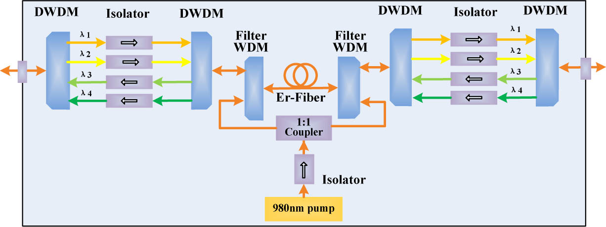
The configuration of the Bi-EDFA in the round-trip FTFT system is shown in Fig. 1. Two channels of dense WDMs (DWDMs) are used to realize the joint 1 GHz frequency and 1 PPS time signals transfer in the same fiber link[14,15]; thus, the DWDMs of the four channels are brought into the Bi-EDFA to isolate the frequency and time signals in two directions. Channels and are used for the forward transfer, while and are for the backward transfer. The channel spacing is 100 GHz (0.8 nm) with a passband of 55 GHz (0.44 nm). Such channels also serve as narrow-band optical filters, which can remove most ASEs. Each channel contains an optical isolator to ensure the cancellation of the reflections from the connectors, Rayleigh backscattering signals, and ASEs in the reverse direction. All of the optical fiber junctions are fusion spliced to avoid unwanted oscillations. To maintain the high symmetry of propagation in both directions, the signals are amplified in the same erbium-doped fiber and pumped in both directions through the same 980 nm pump laser by a coupler with a 1:1 coupler ratio. The length of the erbium-doped fiber (Er40-4/125 from nLIGHT) is 5 m, and the erbium concentration is .
Sign up for Chinese Optics Letters TOC. Get the latest issue of Chinese Optics Letters delivered right to you!Sign up now

Figure 1.Configuration of the proposed Bi-EDFA.
The test scheme for the noise and asymmetry properties of the Bi-EDFA in the transfer of the joint frequency and time signals is shown in Fig. 2. The experimental temperature is without air conditioning. Optical attenuators are inserted instead of the transfer optical fiber to avoid the instability caused by the fiber. By measuring the propagation delay variations of the frequency or time signals in two directions with and without the Bi-EDFA, the noise property of the Bi-EDFA can be obtained. The real-time differences of the propagation delay variations between the two directions with and without the Bi-EDFA reflect the asymmetry property of the Bi-EDFA.
Figure 2.Measurement setup of noise and asymmetry properties.
At the local end, a 1 GHz frequency and 1 PPS time signals are intensity modulated on two independent transmitter modules ( and ), which contain an electro-optic modulator and a distributed feedback (DFB) laser. The output powers are and . Combined with a WDM and after passing through a circulator, the two carriers enter the fiber link, which is simulated by two optical attenuators. At the remote end, the frequency and time signals are detected by two photodiodes with input powers of and ; the photodiodes are placed after a circulator and a WDM. Through the same process, the frequency and time signals (, and the output powers of the two transmitter modules are , ) at the remote end reappear at the local end with detected powers of and , respectively, The reference and transferred signals at both the local and remote ends originate from one frequency and time signal generator. The losses of adjustable attenuator and attenuator are set to 19 and 20 dB, respectively, to simulate about a 76 and an 80 km common fiber with a 0.25 dB/km loss coefficient. The pump power of the Bi-EDFA is 150 mW, reaching gains of 22 dB forward and 23 dB backwards. For the purposes of comparison, the input powers of the detectors are kept the same as the above when the Bi-EDFA is removed in Fig. 2.
First, the propagation delay fluctuations of the 1 GHz signal in both directions are measured. At the local end, the backwards propagation delay fluctuations are obtained by comparing the reference signal with the 1 GHz signal sent from the remote end by phase discriminator (PD) A with a 5 Hz bandwidth. In Fig. 3(a), and represent the real-time situations with and without the Bi-EDFA, respectively, and their stabilities as conventionally characterized by the Allan deviation (ADEV) are shown in Fig. 3(b). At the remote end, the forward propagation delay fluctuations are obtained by following the same method used at the local end. Figure 4(a) shows the results with and without the Bi-EDFA, that is, and , respectively, and their ADEVs are shown in Fig. 4(b). Figures 3 and 4 confirm that the delay fluctuations with the Bi-EDFA are slightly larger than that without the Bi-EDFA. In the backward direction, the ADEVs are only degraded by at 1 s and at . In the forward direction, the relative values are at 1 s and at . These results may be attributed to the use of WDM filters and isolators in the Bi-EDFA, which can block most of the ASEs and ASE–ASE beat noise, as well as the backscattering signals and reflections. The real-time differences of the propagation delay fluctuations between the two directions, and are shown in Fig. 5(a), and their ADEVs are shown in Fig. 5(b). The deteriorated ADEVs caused by the asymmetry of the Bi-EDFA are at 1 s and at . The electrical noise floor of the measurement setup is obtained by feeding two frequency signals from the 1 GHz generator directly into the PD.
Figure 3.Backwards propagation delay fluctuations. (a) Real-time and (b) ADEV. : with Bi-EDFA. : without Bi-EDFA.
Figure 4.Forward propagation delay fluctuations. (a) Real-time and (b) ADEV. : with Bi-EDFA. : without Bi-EDFA.
Figure 5.Difference of propagation delay fluctuations. (a) Real-time and (b) ADEV. : with Bi-EDFA. : without Bi-EDFA.
Second, the propagation delay fluctuations of the 1 PPS signal in both directions are also measured. At the local end, the backward propagation delay fluctuations of 1 PPS are obtained by comparing the reference signal with the 1 PPS signal sent from the remote end by time interval counter (Stanford SR620). The sample interval is 1 s, and and represent the real-time situations with and without the Bi-EDFA, respectively. At the remote end, the forward propagation delay fluctuations of 1 PPS are obtained by the same way as at the local end, and and are the results with and without the Bi-EDFA, respectively. Correspondingly, and are the differences of the propagation delay fluctuations with and without the Bi-EDFA. The real-time results of , , , and are similar to those of the 1 GHz signal. The mean values of and are 24.514 and 22.764 ns, respectively, which are the absolute backward and forward propagation delays caused by the Bi-EDFA. The calibrated time of the propagation delay difference of the Bi-EDFA is 1.750 ns. The respective time deviations (TDEVs) of and are displayed in Fig. 6. The degraded TDEVs caused by the asymmetry of the Bi-EDFA in two directions is only 0.8 ps at an average time of . The electrical noise floor is obtained by feeding two 1 PPS signals from the 1 PPS generator directly into the SR620.
Figure 6.TDEV of time propagation delay fluctuations. : with Bi-EDFA. : without Bi-EDFA.
When the proposed Bi-EDFA is used to transfer the frequency and time signals of a hydrogen clock with a fiber link reaching 100 km, the additional noise introduced by the Bi-EDFA is small relative to the stability of at 1 s and at of the hydrogen clock itself[16,17]. Furthermore, the delay variation of the 100 km fiber induced by temperature is about 3.7 ns (the thermal-sensitive coefficient of a fiber is typically 37 ps/(km °C)), assuming the daily temperature change of the field fiber is 1°C. It is also much bigger than the fluctuation of the propagation delay differences caused by the asymmetry of the Bi-EDFA. As a result, the proposed Bi-EDFA is highly suitable for use in the transfer of a hydrogen clock in a long fiber link.
To verify the practical application of the Bi-EDFA, the round-trip FTFT with one Bi-EDFA in a 110 km field fiber is tested. The experimental setup is shown in Fig. 7. A 10 MHz frequency signal from a hydrogen clock is multiplied to a higher frequency (1 GHz) since generally, the DFB laser has lower-intensity noise at higher frequency levels. At the remote end, it is demultiplexed to 10 MHz for users. A 1 PPS time signal is also locked to the same clock. The total loss of a 45.3 km field fiber, piezoelectric optical delay line (ODL) and temperature-controlled (TC) ODL is 19 dB. The loss of the 65.5 km field fiber is 20 dB. The gains of the Bi-EDFA are 22 dB forward and 23 dB backwards. All the output powers of the transmitter modules and the input powers of the photodiodes are the same as those in the lab experiment. The returned frequency and reference are sent to the phase detector to obtain the phase noise, which is processed by the proportional-integral-differential circuit to control the piezoelectric ODL and TC ODL, thus compensating for the fluctuation noise along the fiber. From the local end, the results of the phase and time analysis are obtained. The ADEVs of 1 GHz is at 1 s and at , as shown in Fig. 8(a). The TDEV of 1 PPS in Fig. 8(b) is 6.8 ps at .
Figure 7.Experimental setup exploiting one Bi-EDFA in the transfer system via a 110 km field fiber. TDC: time delay counter. PDA: pulse distribution amplifier.
Figure 8.Results of the transfer system in 110 km field fiber link. (a) ADEV. (b) TDEV.
When the Bi-EDFA is applied in the FTFT system based on WDM technology, four carriers are amplified in the same erbium fiber, which is very different from other applications of Bi-EDFAs[10,12,18]. Compared with successive frequency signal, 1 pps has a duration of 20 μs and it will show typical overshooting distortion after amplification[19], as shown in Fig. 9(a). Such distortion is an effect of the rapid reduction of population inversion in the Bi-EDFA. When the 1 GHz successive signal is amplified in another channel at the same time, it has the same distortion as shown in Fig. 9(a), which is the saturation-induced crosstalk effect.
Figure 9.1 PPS and 1 GHz signals after amplification with different input powers into the detector. (a) 3 and (b) 5 μW.
Though the distortion has no influence on the leading edge of the 1 PPS signal, a problem may exist. If the trailing edge of the 1 PPS signal does not reach the triggering level of the pulse distribution amplifier (PDA) even though the leading edge does, the width of the 1 PPS signal will become shorter at the remote end. More seriously, if the high level of the pulse has some fluctuations, which may be caused by the power fluctuations of the carriers, the triggering of trailing edge of the 1 PPS signal will occur more than once. As a result, the calibration of the time will be false. The distortion of the 1 PPS signal can be solved by increasing the pump power of the Bi-EDFA properly to raise the input power into the detector of the 1 PPS signal, making the average powers of the leading edge and trailing edge of the 1 PPS signal both beyond the saturating power of the photodetector; the result is shown in Fig. 9(b). However, if the link is very long, just increasing the pump power has no effect, but introduces stimulated Brillouin scattering[20]. Subsequently, a PDA with a flexible triggering level should be considered, to make the triggering level lower than trailing edge of the 1 PPS signal. As shown in Fig. 9, even though the distortion of the 1 PPS signal has been suppressed, the distortion of the frequency exhibits no change. In the field link experiment, comparing the stability of the system in two situations, with and without the 1 PPS signal, the results are almost the same. The distortion can be regarded as an amplitude modulation of the frequency signal with a short time (20 μs) relative to 1 s. No significant harmonic wave is found, verifying that the distortion of frequency can be negligible. However, if the channels increase, for example, and more time and frequency signals need to be transferred or these signals are transferred together with the digital signals in a telecommunications fiber, the crosstalk becomes more complicated and the influence on the frequency stability may not be ignored any longer. The distortion of the frequency would also play a part when the transfer distance becomes longer and more Bi-EDFAs are exploited. In this case, the isolated amplification between the frequency and time signals must be considered.
In this Letter, a specific Bi-EDFA used in the transfer of joint frequency and time signals based on WDM technology is proposed. The Bi-EDFA of this structure has low noise because it can effectively cancel reflections from the connectors, Rayleigh backscattering signals, and most of the ASEs and ASE–ASE beat noise. The degraded ADEVs are only at 1 s and at in the forward direction. In the backward direction, the corresponding values are at 1 s and at . Furthermore, the configuration of the proposed Bi-EDFA has high symmetry. The deteriorated ADEVs caused by the symmetry of the Bi-EDFA are at 1 s and at , and the corresponding degraded TDEV is only 0.8 ps at . With the Bi-EDFA, joint 1 GHz frequency and 1 PPS time signals are successfully transferred through a 110 km field fiber. The ADEVs of 1 GHz are at 1 s and at . The TDEV of the 1 PPS time signal is 6.8 ps at . The results show that the proposed Bi-EDFA is quite suitable for highly precise clock-signal transfer and comparison through a long-distance fiber link. Furthermore, it can be widely used in future 5G or 6G telecommunication systems. These systems need a more precise time-synchronization property, which means that adopting the round-trip method is an essential requirement. Moreover, regardless of the design flexibility or cost reduction of future optical communication networks, especially in wide-area and loop networks, bidirectional signal transfer will be necessary and the proposed Bi-EDFA would be a better choice for such bidirectional transmission. In the end, the influence of the transient gain saturation effect of 1 PPS, which leads to the distortions of the 1 PPS and 1 GHz signals, on the transfer system is discussed. The distortion of the 1 PPS signal can be solved by choosing a PDA with a flexible triggering level. Though the distortion of the 1 GHz signal cannot be canceled, it almost has no influence on the stability of the frequency.
References
[1] T. Heavner, E. Donley, F. Levi, G. Costanzo, T. Parker, J. Shirley, N. Ashby, S. Barlow, S. Jefferts. Metrologia, 51, 174(2014).
[2] I. Ushijima, M. Takamoto, M. Das, T. Ohkubo, H. Katori. Nat. Photon., 9, 185(2015).
[3] W. Tseng, S. Lin, K. Feng, M. Fujieda, H. Maeno. IEEE Trans. Ultrason. Ferroelectr. Freq. Control, 57, 161(2010).
[4] O. Lopez, A. Amy-Klein, C. Daussy, C. Chardonnet, F. Narbonneau, M. Lours, G. Santarelli. Eur. Phys. J. D, 48, 35(2008).
[5] Z. Zhang, Z. Cao, X. Chen, L. Wang, M. Zhang. Chin. Opt. Lett., 11, 120602(2013).
[6] X. Cao, B. Wu, X. Hong, J. Wu, J. Lin. Chin. Opt. Lett., 10, 070606(2012).
[7] K. Predehl, G. Grosche, S. F. M. Raupach, S. Droste, O. Terra, J. Alnis, T. Legero, T. W. Hänsch, T. Udem, R. Holzwarth, H. Schnatz. Science, 336, 441(2012).
[8] D. Calonic, E. K. Bertacco, C. E. Calosso, C. Clivati, G. A. Costanzo, M. Frittelli, A. Godone, A. Mura, N. Poli, D. V. Sutyrin, G. Tino, M. E. Zucco, F. Levi. Appl. Phys. B, 117, 979(2014).
[9] M. Amemiya, M. Imae, Y. Fujii, T. Suzuyama, S. Ohshima. Proceedings of the IEEE International Frequency Control Symposium and Exposition, 914(2005).
[10] O. Lopez, A. Amy-Klein, M. Lours, C. H. Chardonnet, G. Santarelli. Appl. Phys. B Lasers Opt., 98, 723(2010).
[11] Ł. Śliwczyński, P. Krehlik, M. Lipiñski. Meas. Sci. Technol., 21, 075302(2010).
[12] Ł. Śliwczyński, P. Krehlik, Ł. Buczek, M. Lipiñski. IEEE Trans. Instrum. Meas., 61, 2573(2012).
[13] Ł. Śliwczyński, J. Kołodziej. IEEE Trans. Instrum. Meas., 62, 253(2013).
[14] F. Yang, D. Xu, Q. Liu, N. Cheng, Y. Z. Gui, H. W. Cai. The CLEO: Science and Innovations, JTu4A99(2013).
[15] W. Chen, Q. Liu, D. Xu, N. Cheng, F. Yang, Y. Z. Gui, H. W. Cai. IEEE Photon. J., 7, 7901609(2015).
[16] S. M. Foreman, K. W. Holman, D. D. Hudson, D. J. Jones, J. Ye. Rev. Sci. Instrum., 78, 021101(2007).
[17] A. M. Zhang, W. B. Wang, Y. Gao, K. Liang, Z. Q. Yang, K. Liu. 2014 IEEE International FCS, 14470314, 1(2014).
[18] M. Amemiya, M. Imae, Y. Fujii, T. Suzuyama, F. Hong, M. Takamoto. IEEE Trans. Instrum. Meas., 59, 632(2010).
[19] C. R. Giles, E. Desurvire. Opt. Lett., 14, 880(1989).
[20] W. Chen, Z. Meng. Chin. Opt. Lett., 8, 121124(2010).