Hang Zhou, Zilun Chen, Xuanfeng Zhou, Jing Hou, Jinbao Chen. All-fiber 7 × 1 signal combiner with high beam quality for high-power fiber lasers[J]. Chinese Optics Letters, 2015, 13(6): 061406
Copy Citation Text
All-fiber signal combiner is a key component for augmenting the fiber laser power. Presently the reported signal combiners are all have output fibers with core diameters larger than 100 μm. In order to improve the beam quality of the combiner, a fiber with smaller core of 50 μm diameter is chose to be the output fiber. An all-fiber signal combiner is fabricated with measured power transmission efficiency around 99% for each port. The beam quality is improved and the measured are around 6 which are matched well with the theoretically calculated results.
Fiber lasers which have the output power extended into kilowatt (kW) regime have applied in many fields due to their advanced features such as high beam quality, compactness, and thermal management[1–6]. However, the output power of fiber laser from a single fiber is limited by strong nonlinear effects. In order to achieve higher power output, incoherent beam combining through signal combiner has been found to be a significantly easy way[7–9]. Nowadays, the applications of combined fiber lasers have drawn increasingly more attention on the beam quality of the combiner in addition to the output power.
In 2011, Noordegraaf[10] reported an all-fiber signal combiner which supported up to 2.5 kW combined output power and only a minor temperature increase was observed. At an intermediate power level of 600 W the beam parameter product (BPP) was measured to be 2.22 mm·mrad, corresponding to an value of 6.5. Yan[11]et al. achieved a 4 kW continuous-wave (cw) fiber laser with an all-fiber signal combiner, and the coupling efficiency was nearly 98%. In Ref. [12], Shamir et al. reported a 3 kW level incoherently combined laser with a measured power transmission efficiency of 98% using an all-fiber Y-branch combiner, and the factor of was measured at a 600 W output level.
However, although fiber signal combiners supporting kW laser output have been reported, the output fiber cores are almost larger than 100 μm and the beam quality cannot be improved. In Ref. [11] the output fiber had a core of 50 μm, but the manufacture details were not given clearly and the beam quality was not measured. The influence of adopting smaller-core fiber as output fiber on the beam quality of combiner has not been studied and reported (to our best knowledge). Theoretically using fiber of smaller core as the output fiber can improve the beam quality of the output optical field effectively. In this work, we investigate the beam quality of a 7×1 signal combiner with smaller output fiber. First, we theoretically analyze the power transmission efficiency and the beam quality of signal combiner. Then experiments are conducted to fabricate signal combiners based on the theoretical results. The beam quality of the fabricated signal combiner is measured and the beam quality factors are 6.0 and 6.3 which are better than that of signal combiner with larger-core output fiber. Moreover with the power transmission efficiency is also measured to be as high as around 99% for each port.
Sign up for Chinese Optics Letters TOC. Get the latest issue of Chinese Optics Letters delivered right to you!Sign up now
In order to fabricate fiber combiners of high transmission efficiency, two basic principles should be followed: adiabatic tapering and brightness conservation. Adiabatic tapering is using a long enough taper length to ensure the taper angle is small enough. Based on adiabatic tapering, the optical field propagating in the tapered fiber bundle will not change dramatically. Thus the transmission efficiency in the taper region will be high. Through theoretical analysis, a suitable taper length of the fiber bundle is calculated to ensure a high transmission efficiency of the combiner. The taper length of the fabricated combiner is equal to the calculated taper length.
Brightness conservation is the other important principle in the design of fiber combiner. If the incident optical field is uniform, the integrated brightness (IB) can be expressed as where is the optical field area, is the radiation intensity contour, and and is the receiving angle of fiber.
The numerical aperture (NA) of fiber is proportional to , and , so
The optical field area can be approximated as , where is the fiber core diameter. Thus
From Eq. (3), brightness conservation can be understood as that is maintained a constant in the tapering process.
In the theoretical analysis a step-index double cladding fiber with a core of 20 μm and an inner cladding of 130 μm ( and 0.46, respectively) is chosen to be the signal fiber of signal combiner, so the equivalent diameter of the taper fused bundle (TFB) is 390 μm. The diameter of the output fiber core is 50 μm, so the taper ratio of TFB is . With thus a large taper ratio, the optical field area cannot be approximated by .
Generally, the optical filed is propagation in the fiber core and the fiber core diameter decreases along the taper. The normalized frequency also decreases as per where n1 and n2 are the refractive indexes of the fiber core and cladding, respectively.
According to the taper ratio, the input fiber core radius at the end face of the taper region is 1.28 μm; thus we can obtain .
When the value is smaller than (core-mode cutoff ) the optical field will leak to the cladding and become a cladding mode where is the diameter ratio the fiber cladding and core. In this work , so is about 0.969.
Therefore, we can know that , and thus the optical field will leak to the fiber cladding. Under this situation the optical field area cannot be estimated by but should be calculated carefully. Through beam propagation method (BPM) the optical field diameter is calculated to be 13 μm. The NA at the end face of the taper region can be obtained as which is less than that of the output fiber. The optical field cannot fully fill the core of the output fiber. Consequently there is no loss existing theoretically and a high transmission efficiency combiner can be fabricated.
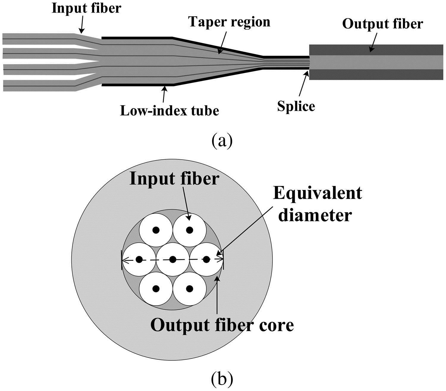
Generally, the fabrication process of a combiner is composed of three steps, namely tapering, cleaving, and splicing[8,9], among which tapering is the most important step. In this step, the seven signal fibers are inserted into a fluorine-doped low-index capillary in parallel. This capillary is fused with the fiber bundle into a single entity by filament. The single entity can be regarded as a special fiber that has seven cores and a cladding formed by the low-index capillary tube. In this context we define an equivalent diameter for this entity as shown in Fig. 1(b). Then tapering this single entity to have the equivalent diameter matched up with the core diameter of 50 μm of the output fiber (). The tapering process should be adiabatic and satisfy the brightness conservation condition to reach low loss[13–16]. The single entity is cleaved where the tapered bundle has a diameter equal to the core of the output fiber and spliced with the output fiber and then a combiner is obtained.
Figure 1.(a) Schematic of the signal combiner fabricated by capillary method; (b) cross section of the signal combiner at the splice point.
In the simulation, the compute step length is set to be 0.2 μm in the BPM simulation which is much smaller than the wavelength of input laser, and set the refractive index of the capillary tube (about 1.43) in the simulation according to the experiment. The power transmission efficiency is calculated under different taper lengths and the results imply that when the taper length is longer than 8 mm the power transmission efficiency can be higher than 99%. In the following simulations and experiments 10 mm long taper is chosen. Then the optical fields of the tapered fiber bundle at the original and the end faces are calculated by BPM and shown in Figs. 2(a) and 2(b). It can be found that the optical field becomes smaller along the taper and in the end the optical field can be covered by the core of the output fiber. Then after propagating in the output fiber, the output optical field is obtained as shown in Fig. 2(c). Based on scalar diffraction theory the optical far field can be obtained as shown in Fig. 2(d). Then the beam quality factor of the output light from the combiner can be calculated[17–19] and the results are and .
Figure 2.Laser field of the combiner at the following: (a) initial location; (b) final end face of the tapered bundle; (c) output laser field of the combiner; (d) far field of the output laser from the combiner.
Based on the calculated results, we fabricated a signal combiner using a Vytran 3400 system. Seven fibers with core diameter of 20 μm and inner-cladding diameter of 130 μm (core and cladding NA of 0.08 and 0.46, respectively) are inserted into a capillary. The inner and outer diameters of this capillary are 800 and 1500 μm, respectively. These fibers and the capillary comprise a bundle. Then this bundle is tapered until all the fiber cores can be covered by the core of the chosen output fiber of the combiner. In the experiment, the output fiber has a core diameter of 50 μm. According to the inner/outer diameter ratio of the capillary, the diameter of the bundle is tapered to be 85 μm. The cross sections of the original bundle, an arbitrary location in the transition region and the final end-face of the tapered bundle are shown in Figs. 3(a)–3(c). Thus, a signal combiner is obtained.
Figure 3.Cross sections: (a) original bundle; (b) arbitrary location in the transition region; and (c) final end-face of the tapered bundle.
Then the transmission efficiency of the combiner is tested by a 5 W cw fiber laser at 1064 nm. For measuring the transmission efficiency, the fiber laser is in turn spliced to each signal port of the combiner. The efficiencies are measured and shown in Fig. 4. All ports have approximately the same high efficiency with an average value close to 99%. Limited by the output power of the fiber laser, high-power test of the combiner has not been performed. However, we believe that the power transmission efficiency which is as high as 99% can ensure the high-power operation of the combiner.
Figure 4.Transmission efficiencies of each port of the combiner.
The beam quality of the output laser from the combiner is measured by launching seven fiber lasers at 1064 nm each with 2 W of output power into the 7 input ports. An -200 s laser beam profiler (Spiricon) is utilized. The measured result is presented in Fig. 5 and the values are 6.0 for the -axis and 6.3 for the -axis which are both slightly higher than the simulation results which may be induced by some defects introduced during the fused tapering and splicing processes.
Figure 5. measurement of the combiner by launching seven fiber lasers at 1064 nm each with 2 W of output power into the seven input ports of the combiner.
In conclusion, a signal combiner with high power transmission efficiency and high beam quality is fabricated. The input fibers are inserted into a capillary with low refractive index and then the whole fiber bundle is tapered to be smaller than the output fiber. Then the tapered bundle is spliced with the output fiber to form a signal combiner. Based on the simulated results, a signal combiner is fabricated with input fibers of 20/130 μm core/cladding diameter and the output fiber with a core diameter of 50 μm. The taper length is chose to be 1 cm which satisfies the simulated result that the taper length should be longer than 8 mm to ensure high power transmission efficiency. The measured power transmission efficiencies of all the input ports are around 99%. And the beam quality factors are 6.0 and 6.3 which are close to the calculated results of 5.7 and 5.9. The simulations and experiments can provide useful guidance for the fabrication of signal combiner with high power transmission efficiency and high beam quality for the applications of high-power fiber lasers. Certainly, high-power measurement experiment is very important. We are trying our best to construct several higher-power fiber lasers to test the obtained signal combiner in the future.
[2] C. H. Liu, A. Galvanauskas, B. Ehlers, F. Doerfel, S. Heinemann, A. Carter, K. Tankala, J. Farroni. Proceedings of Advanced Solid-State Photonics, PDP17(2004).
Hang Zhou, Zilun Chen, Xuanfeng Zhou, Jing Hou, Jinbao Chen. All-fiber 7 × 1 signal combiner with high beam quality for high-power fiber lasers[J]. Chinese Optics Letters, 2015, 13(6): 061406