Digital holographic microscopy using multiframe full-field heterodyne technology is discussed in which two acousto-optic modulators are applied to generate low-frequency heterodyne interference and a high-speed camera is applied to acquire multiframe full-field holograms. We use a temporal frequency spectrum analysis algorithm to extract the object’s information. The twin-image problem can be solved and the random noise can be significantly suppressed. The relationship between the frame number and the reconstruction accuracy is discussed. The typical objects of microlenses and biology cells are reconstructed well with 100-frame holograms for illustration.
Holography was invented by Gabor[1]. Based on interference recording and diffraction reconstructing, one can obtain the object’s 3D information. Digital holographic microscopy (DHM) is a technique that combines digital holography with microscopy. DHM is a non-contacting, non-scanning, non-dyeing, and quantitative technique that could be widely used in biology and microelectromechanical systems (MEMS) areas[2–11].
There are two major problems in a DHM system, the twin-image problem and the random noise problem (from mechanical vibration and air turbulence)[2,3,12]. These problems reduce the reconstruction precision and limit applications of DHM.
Off-axis holography was invented by Leith and Upatnieks[13]. By adding a tilt angle between the object beam and reference beam, the reconstructions of a real image and a virtual image can be spatially separated. However, this configuration limits the number of usable pixels and causes image degradation.
Sign up for Chinese Optics Letters TOC. Get the latest issue of Chinese Optics Letters delivered right to you!Sign up now
Phase-shifting digital holography, invented by Yamaguchi[14,15], is an efficient technology that suppresses the twin-image term, and its on-axis configuration allows efficient use of the detector. The phase shifting is achieved by moving the mirror with a piezoelectric transducer (PZT). Four-step holograms that have phase shifting were detected. Using corresponding algorithms, the twin-image term could be eliminated. However, the phase-shifting accuracy is affected by nonlinear error, which limits the precision of the reconstructed image[16].
The heterodyne method can solve the precise phase-shifting problem. Optical scanning holography (OSH) was invented by Poon[17–19]. This technology uses an acousto-optic modulator (AOM) to create a MHz-order frequency heterodyne to get a time-dependent Fresnel zone plate (TDFZP). Then, point detection and 2D scanning are used to create a hologram. Electron devices are used to create a second complex hologram from the first detected real hologram. This system can also eliminate the twin-image term.
Full-field heterodyne holography, proposed by Le Clerc[20], uses two AOMs to create a low-frequency heterodyne. It is able to get holograms with a full-field camera other than by point detection. By processing the four-step phase-shifting holograms, the twin-image term can be eliminated as well. Off-axis heterodyne holography was proposed by Gross to achieve an ultimate sensitivity[21]. Furthermore, the noise and signal scaling factors in heterodyne holography were discussed[22].
In these DHM systems, the phase shifting is 4 steps in order to suppress the influence of the twin-image term. Sometimes multiple periods of holograms are recorded for time averaging to suppress the influence of random noise. In the case of a high precision phase-shifting interferometer, multiple steps of phase-shifting interference patterns are detected and processed with corresponding algorithms to reduce the nonlinear error of a PZT and random noise[16,23,24]. Even a 101-frame algorithm for phase-shifting interferometry was proposed[25].
To combine the advantages of multiperiod and multistep phase-shifting technology, a multiframe full-field heterodyne DHM is proposed. Low-frequency heterodyne AOMs, a high-speed camera, and a multiframe temporal signal processing algorithm are applied to this DHM system.
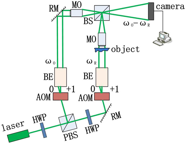
The DHM system is an on-axis holographic system based on a Mach–Zehnder configuration, as shown in Fig. 1. Two AOMs of MHz-level modulating frequency are applied to modulate the object beam and reference beam, and the modulating angular frequencies are and . In the object channel, the beam illuminates the object and is collected by a microscope objective (MO). In the reference channel, a second MO is used to compensate the phase curve in the object channel. The object beam and the reference beam are combined by a beam splitter (BS) and generate low-frequency heterodyne interference holograms. Then the multiframe full-field holograms could be recorded by high-speed camera.
Figure 1.Schematic diagram of a multiframe full-field heterodyne DHM. HWP: half-wave plate, PBS: polarizing beam splitter, RM: reflective mirror, and BE: beam expander.
In previous work, we developed a high-quality Hz-order heterodyne frequency signal generator, and the high-speed camera is commercially available[26]. Compared with other high-speed holography, the phase shifting of the proposed heterodyne method is more linear and precise than the PZT method[27], and can fully use the pixels of the camera without spatial segmentation[28]. What is more, phase-locked technology was used in the AOM’s signal generator, which can ensure the phase synchronism between two channels. This is more easily achieved[29].
The object wave of this system is
The reference wave of this system is
The ideal hologram without noise is
The relationship between the heterodyne angular frequency and the heterodyne frequency of the AOMs is
The expansion of Eq. (3) is
The phase and amplitude of the object is recorded in the third item with modulating the angular frequency of . The twin-image and direct current (DC) terms are recorded in other temporal frequencies.
In addition, the signal with random noise is
The relationship between , recording time , and recording period is shown as
The relationship between the frame rate of camera , phase-shifting steps , and is
The relationship between the recording hologram numbers , , and is
For example, with a 200 fps recording speed and a 10 Hz heterodyne frequency interference, 200 holograms of 10 periods and 20 steps can be gotten in 1 s. These holograms format a 3D matrix. A temporal modulated signal can be gotten from each pixel of the camera.
Regarding the object, the twin-image and the DC terms have different modulating frequencies in Eq. (5), and they can be easily separated in the temporal frequency spectrum. Thus, a temporal frequency spectrum analysis algorithm, such as the fast Fourier transform (FFT) algorithm, is selected to process the signal of each pixel. According to the Nyquist–Shannon sampling theorem, when is twice , the object information can be extracted from the third term of Eq. (5) at the corresponding frequency spectrum point, which is
For the signal with random noise, the calculated value at frequency is
The detail of Eq. (11) is
Part of the value is the mathematical expectation of , which is
The random noise is very complex, which includes vibration, turbulence, etc. If the statistical distribution of this noise is a normal distribution[3,30,31] and the expectation , the probability density function is where is the standard deviation.
The characteristic functions are
The mathematical expectation of equals is
Then the result of Eq. (12) is
In the distinct form of Eq. (12), as the frame number increases, the result can more approach in Eq. (17).
The procedure of extracting the amplitude of the demodulated complex value is
In Eq. (18), Re represents the real part and Im represents the imaginary part. As is a constant, the normalization of can be gotten by normalizing.
The procedure of extracting the phase of the demodulated complex value is
The phase unwrapping process is done, with the result in Eq. (19), which is common procedure in theDHM algorithm[2,3]. As a second MO is used to compensate the phase curve in the object channel, the unwrapped phase represents the phase of the object.
The traditional four-step phase-shifting algorithm is where , , , and are 4 holograms with phase shifting, and is the phase of the object wave. This method can also be explained as using 4 discrete items to get a Fourier coefficient, which is in essence similar to the proposed multiframe method.
The main factors in the proposed method are , , and . affects the computation accuracy, which is shown in Eqs. (13) and (16). Thus, a long recording time and a high frame rate are needed. affects the bandwidth of the FFT spectrum. As the increases, the modulated signal can flexibly keep away from different noise frequencies in different environments. What is more, a larger leans to a larger and better precision under the same number of periods.
To verify the relationship between , , , and the reconstruction precision, a simulation is done and is shown in Fig. 2. varies from 1 to 20, and values of 4, 10, and 100 are selected for illustration. varies from 4 to 2000. The of random noise is set to 0.1. Each point of the results is a statistic of 200 times repetition. The root-mean-square error (RMSE) is defined as
Figure 2.Reconstruction error under different periods and steps.
where is the repeat number, is the reconstruction data, and is the ideal data.
As the number of periods and steps increased, the reconstruction error decreased. Frame numbers should be as large as possible theoretically. However, the number is limited by the recording time, array size, signal processing speed, etc. Thus, parameters of this system should be set for different needs.
In addition, to verify the relationship between the modulation frequency and the reconstruction precision, a simulation is shown in Fig. 3. The detection speed is 100 fps, the of the random noise is set to 0.1, and the heterodyne frequency varies from 9.9 to 10.1 Hz.
Figure 3.Reconstruction phase error under different modulation frequencies.
As shown in Fig. 3, the modulation frequency obviously affects the reconstruction precision, which makes a strict requirement for the driver of AOMs.
Moreover, in the practical recording of the holograms, there are other kinds of nonrandom noise that cannot be eliminated just by the multiframe method. These kinds of noise also exist in traditional DHM systems and have been well discussed[3,16]. Here, we give a brief discussion of these additional effects. The system error should be detected though measuring a standard object, and subtracting it in each result; the discretization error can be improved by increasing the bit number of the camera, which is inversely proportional to the detection speed and should be selected carefully; the shot noise of the camera limits the SNR of the recorded hologram, which can be improved by increasing the light intensity, but should also consider the tolerance of the living cell.
A demonstrating experiment was set up. The main devices are as follows: laser (Coherent Corporation Verdi 6, 532 nm), MO (Daheng Optics Corporation, , ), high-speed camera (Baumer Corporation, hxc13, pixels, 500 fps), microlenses (Advanced Micro-Optic Systems GmbH, diameter 90 μm), biology cell (Institute of Genetics and Developmental Biology, Chinese Academy of Sciences, mouse cell).
The driver of low-differential AOMs is developed by our group, which proves a precise heterodyne signal. The design beat frequency is 10 Hz and the actual measurement is , the phase noise is , and the harmonic noise is .
First we do the experiment with microlenses. is 100 fps and 100 frame holograms were gotten in 1 s. Ten-step holograms in 1 period are shown in Fig. 4.
Figure 4.Ten-step phase-shifting holograms of 1 period.
For each pixel of the hologram, a temporal signal of 100 samples was gotten. The signal of one pixel is shown in Fig. 5(a), in which the phase shifting is linear and precise. Then process signal is processed with an FFT to obtain the frequency spectrum, which is shown in Fig. 5(b).
Figure 5.(a) Sample data of one pixel of microlenses and (b) the frequency spectrum of the sample data.
The reconstructed amplitude and phase are shown in Figs. 6(a) and 6(b). The unwrapped phase is shown in Fig. 6(c), and a 3D view is shown in Fig. 6(d). The result indicates the feasibility of the proposed technology.
Figure 6.(a) Amplitude of microlenses, (b) the phase of microlenses, (c) the unwrapped phase of microlenses, and (d) a 3D view of the reconstructed microlenses.
Then we change the experiment system to the inverted configuration and deal with a non-dyeing mouse cell. One hundred holograms of the cell were recorded. One hologram is shown in Fig. 7(a), the frequency spectrum of one pixel is shown in Fig. 7(b), and a 3D view of the reconstruction cell is shown in Fig. 7(c).
Figure 7.(a) One hologram of the mouse cell, (b) the frequency spectrum of one pixel, and (c) a 3D view of the reconstruction cell.
As shown in Fig. 7(a), the SNR of the nondyeing cell is not very high. However, with multiframe holograms and the temporal frequency spectrum analysis algorithm the reconstructed object is clear, as shown in Fig. 7(c).
In conclusion, we propose a multiframe full-field heterodyne DHM. Using a low-frequency heterodyne signal and a high-speed camera, multiframe holograms can be gotten. By extracting the information of each pixel from a temporal frequency spectrum, the influence of a twin image can be effectively eliminated. As the frame numbers increase, the statistical value of the noise in the heterodyne frequency approaches a constant. As a result, this method can reduce the influence of twin-image and random noise, which makes it adaptable for different precision requirements.
We demonstrate the efficiency of this technology in the theory, the simulations, and the experiment. The phase shifting is linear and accurate and the reconstructed images of the microlenses and the cell are clear and sharp.
This system is able to perform a quantitative 3D imaging without dyeing or 2D scanning of the sample, which can be widely used in MEMS and biology research areas.