Abstract
We investigate a novel Smith–Purcell terahertz source. This device is composed of an electron gun, a cylindrical resonator, a metallic grating, and a collector. The characteristics of the Smith–Purcell terahertz source are discussed with the help of three-dimensional particle-in-cell simulation. In this device, coherent and high-power Smith–Purcell radiation (SPR) at the terahertz frequency range can be produced for the reasonable parameters of charge energy and grating. Our results indicate that coherent SPR at 506.529 GHz with a power around 1000 W can be obtained for a grating of period l = 0.3 mm operating at the beam energy E = 50 keV and beamcurrent I = 10 A.1. INTRODUCTION
As is well known, terahertz (THz; 0.1–10 THz) technology, a currently active research area, is finding use in an increasingly wide variety of applications including far-infrared spectroscopy, medical and industrial imaging, biomedical research, and material science. Increasing access to THz technologies requires the development of THz sources. There are a number of ways to generate THz radiation. In photonics, quantum cascade lasers (QCLs), solid state oscillators, and optically pumped solid state devices have been developed, which can provide coherent THz radiation. In microwave electronics, the THz vacuum electron devices based on charge oscillations like klystrons, traveling wave tubes, backward wave oscillators (BWOs), and gyrotrons have been extensively studied. In these THz sources, the QCL and BWO have reached full maturity and have been widely employed [1–3]. The QCL can emit at 4.4 THz, providing about 2 mW of average power with 10% duty cycle at an operating temperature of 50 K. The BWO can be implemented to cover altogether a wide frequency range extending from 30 GHz to 1.2 THz. Free electron laser (FEL), solid state oscillators, and an optically pumped solid state can also be built in the THz region. For example, the first FEL can provide tunable THz radiation in the region from 120 GHz to 4.8 THz (2.5 mm–60 μm) with an output power in the range from 500 W to 5 kW and a pulse duration of 1–20 μs at 1 Hz repetition rate. The average power level of the solid state oscillators achievable in the region around 400 GHz is typically in the range 0.1–1 mW. The typical frequency range of devices covered by laser driven solid state emitters is 0.2 to 2 THz or higher. Moreover, in THz vacuum electron devices, the Smith–Purcell (SP) radiation (SPR) is one particularly promising choice for developing THz sources [4–11]. Compared with other THz source, SPR is a promising candidate for developing a more compact, less complex, and lower cost THz source. This paper demonstrates a simple method to generate powerful THz radiation by observing SPR. This novel SP THz source is composed of an electron gun, a cylindrical resonator, a metallic grating, and a collector. Compared with other SP THz sources, this novel SP THz source is capable of providing high power THz radiation. The characteristics of this device are studied by a three-dimensional (3D) particle-in-cell (PIC) simulation method.
2. BASIC THEORETICAL BACKGROUND
When a sheet electron beam passes over a periodic metallic structure (like a diffraction grating) along the direction of its spatial periodicity, electromagnetic radiation is emitted in all directions. This electromagnetic radiation is called SPR. The radiation mechanism was predicted by Frank and observed by Smith and Purcell [12]. In the SPR, the wavelength of the SPR depends on the SPR formula, where is the ratio of the electron’s velocity to the velocity of light. is the length of the grating period, the integer is the order of the space harmonic wave, and is the emission angle of observation relative to the electron beam direction. According to Eq. (1), an SPR at the THz frequency range can be generated by adjusting the length of the grating period, adjusting the voltage of the electron beam, and adjusting the emission angles. For example, when the length of the grating period and the energy of electron beam , the wavelength region between 1.0269 mm (with corresponding frequency ) and 0.4269 mm (with corresponding frequency ) can be generated.
3. THEORETICAL ANALYSIS OF THE THZ SP SOURCE
Usually, the incoherent SPR is too weak to use, and detection of the signal is very difficult. To generate coherent radiation and amplify electromagnetic waves, a feedback configuration such as open cavity or closed cavity is utilized in experiments. These experiments are important in extending the spectrum and developing tunable coherent radiation [13,14]. In this paper, a novel SP THz source based on a cylindrical resonator developed by our group is presented. The configuration of the SP THz source is schematically shown in Fig. 1. The SP THz source includes an electron gun, a cylindrical resonator, a metallic grating, and a collector. In this technical scheme, a metallic grating with rectangular form is set at the center of the bottom of the cylindrical resonator. The surface of the metallic grating and the cylindrical resonator are assumed to consist of a perfect conductor. The grooves of the metallic grating are parallel and uniform in the direction. A sheet electron beam is propagated along the axis. It is a perfect beam produced from a small cathode (electron gun) located at the left boundary of the grating. As the sheet electron beam passes over the metallic grating, the SPR and the evanescent wave (or grating surface mode) are emitted. The cylindrical resonator reflects the SPR and the evanescent wave back onto the beam and causes the beam to be modulated. If the velocity of the electron is equal to the phase velocity of the evanescent waves propagating in the direction parallel to the surface of the metallic grating, the beam–wave interaction builds up. Moreover, the bunching frequency equals that of the evanescent wave. But at the beginning of the electron beam injection, the SPR and the evanescent wave are not strong enough to cause electron bunching. Thus, collective oscillation is not able to start; the SPR is spontaneous and incoherent. When the injected time exceeds a certain threshold value, called the time of start oscillator, the beam gets bunched by the enhanced evanescent wave. Thus, a steady state oscillation is established in this device at one of the resonant frequencies of the resonator, and the beam–wave interaction reaches a self-exciting condition gradually. As the beam–wave interaction reaches the self-exciting condition, the net gain of the signal can build up in the resonator [15–17]. According to the preceding narrative, the novel SP THz source operates like an Orotron. The device resembles a slow wave structure. Similar to the Orotron-like device, the dispersion relation for the novel SP THz source is found to be where , , , , , , , is the normalized length of resonator, and , , are the slot width, slot depth, and period of the grating, respectively.
Sign up for Photonics Research TOC. Get the latest issue of Photonics Research delivered right to you!Sign up now
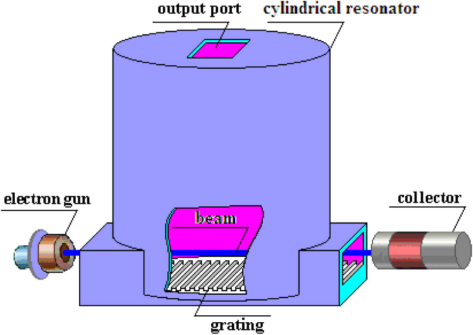
Figure 1.Schematic diagram of the SP THz source.
4. PIC SIMULATION OF BEAM–WAVE INTERACTION
By the PIC simulation method, the characteristics of the SP THz source can be studied.
In the PIC simulations, the Maxwell’s equations are solved usually by the finite-difference time-domain code. The PIC method can simulate complicated processes involving interactions between space charge and electromagnetic fields [15–21]. With the help of the 3D PIC simulation, the characteristics of the SP THz source including the radiation energy and field distribution as well as the interaction processes of electron bunches can be obtained [20]. For obtaining the intense THz radiation, the grating parameters including the groove width and depth and that of the electron beam must be optimal. In this paper, the main parameters of the metallic grating and electron beam are summarized in Table 1. According to Eq. (2) and the parameters in Table 1, the dispersion curve can be given. In the dispersion curve, the intersection point between the beam line and the dispersion curve gives the operating frequency. The radius and length of the cylindrical resonator are optimized according to the operating frequency.
| Period Length of Grating | 0.3 mm | Slot Depth of Grating | 0.15 mm |
| Slot width of grating | 0.2 mm | Number of periods | 18 |
| radius of resonator | 1.125 mm | length of resonator | 2.3625 mm |
| Beam voltage | 50 kV | Current | 10 A |
| Transverse size of beam | 0.5 mm | Axial magnetic field | 2.0 T |
Table 1. Parameters of the Simulations
Figure 2(a) shows the density of electrons in the longitudinal direction when bunching has occurred at time 20.799 ns, and Fig. 2(b) shows the kinetic energy of electrons in bunching state at same time. In Fig. 2, we show a snapshot of the beam just above the grating, along with its distribution in phase space, where denotes the kinetic energy. Strong bunching is apparent in both. In Fig. 2(a), we can note that the smaller the distance between the electron and grating surface is, the more apparent strong bunching is. By counting the distance between the bunched beams we can estimate approximately 0.59 mm for the wavelength, about equal to twice the grating period. This shows that the electron beam is bunched due to the periodical magnetic and electric field near the grating. In Fig. 2(b), we can note that strong bunching is apparent. By counting oscillations of the kinetic energy of electrons we also can estimate approximately 0.59 mm for the wavelength. Evidently, a majority of electrons are in the state of losing energy, and the high-frequency field is increased in power correspondingly. By counting, we also note that the mean energy loss is 3.5–4.5 keV, or 7%–9% of the beam energy.

Figure 2.Phase-space distribution of the SP THz source. (a) Density of electrons at the plane at 20.799 ns; bunching is evident. (b) Kinetic energy of electrons in bunching state.
Figure 3 gives the contour map of the electromagnetic field components , , , , , and at the plane of the novel SP THz source at time ; Fig. 4 gives the contour map of the electromagnetic field components , , , , , and at the plane of the novel SP THz source at the same time; and Fig. 5 gives the contour map of the electromagnetic field components , , , , , and at the plane of the novel SP THz source at the same time. In Fig. 3, the distributions of the field have a rule of distribution at the plane. Through the study of the contour map of the electromagnetic field component , the emission angle is about . According to Eq. (1), the corresponding frequency is about 530.97 GHz at the emission angle . Through the study of Figs. 4 and 5, we can see that the distributions of the field present a symmetric distribution at the plane and plane. It should be noted this kind of field distribution is beneficial to improving the efficiency of beam–wave interaction. From the size of the field distribution, we can draw a conclusion that as a sheet electron beam passes over the grating, a steady state high-frequency field can be established at one of the resonant frequencies of the cylindrical resonator.
Figure 3.Profile distribution of field energy at the plane of the SP THz source.
Figure 4.Profile distribution of field energy at the plane of the SP THz source.
Figure 5.Profile distribution of field energy at the plane of the SP THz source.
The evolution curve of field power S.DA at the output port of the novel SP THz source is shown in Fig. 6(a). When the injected time exceeds the time of the start oscillator, the net gain of the signal can build up in the resonator, and the radiation field begins to increase rapidly. Figure 6(a) shows the time of the start oscillator is about 0.4 ns, and it reaches the saturated power at about 0.8 ns; the amplitude of power is about 1000 W. This simulation shows that coherent SPR is excited with much larger intensity than the incoherent radiation. The corresponding fast Fourier transform (FFT) spectrum is given in Fig. 6(b), showing frequency peaks at 253.265, 506.529, and 761.03 GHz. Apparently there exist two different types of radiation. One is diffraction emission originating from the evanescent wave and diffracted at the ends of grating whose frequency is the evanescent frequency and equal to 253.265 GHz. The other is the coherent SPR enhanced by the microbunching of the electron beam in some special direction corresponding to the second harmonic of the evanescent wave [21]. From the FFT amplitude, the dominant radiation is the second harmonic (506.529 GHz, 9500 W/GHz), which emits at the emission angle of about predicted by the SPR equation, Eq. (1). Of course, due to the beam–wave interaction which reduces the value of the particle velocity, there is a slight discrepancy between the simulation data for the radiation angle of and the theoretical value of the basic SP equation. If we consider the mean energy loss (4 keV), according to Eq. (1), the practical wavelength of the SPR at the emission angle and the corresponding frequency , quite consistent with the frequency of the dominant radiation. From the contour plot of Fig. 3, one can easily understand that the dominant second harmonic radiates at the emission angle of about .
Figure 6.Evolution curve of field power at the output port of the SP THz source. (a) Field power S.DA. (b) Corresponding FFT.
5. CONCLUSIONS
It can be concluded from the simulation results that an SP THz source can be composed of an electron gun, a cylindrical resonator, a metallic grating, and a collector. The characteristics of this device can be studied by theoretical analysis and the PIC simulation method. In this novel SP THz source, coherent and high-power SPR at the THz frequency range can be produced for reasonable parameters of charge energy and grating. Our results indicate that coherent SPR at 506.529 GHz with a power around 1000 W can be obtained for a grating of period operating at the beam energy and beam current .
References
[1] G. P. Gallerano, S. G. Biedron. Overview of terahertz radiation sources. Proceedings of the FEL Conference, 216-221(2004).
[2] B. S. Williams, S. Kumar. Terahertz quantum-cascade lasers. Nat. Photonics, 1, 517-525(2007).
[3] B. Green, S. Kovalev, V. Asgekar, G. Geloni, U. Lehnert. High-field high-repetition-rate sources for the coherent THz control of matter. Sci. Rep., 6, 22256(2016).
[4] J. Urata, M. Goldstein, M. F. Kimmitt. Superradiant Smith–Purcell emission. Phys. Rev. Lett., 80, 516-519(1998).
[5] Y. Zhou, Y. Zhang, S. Liu. Electron-beam–driven enhanced terahertz coherent Smith–Purcell radiation within a cylindrical quasi-optical cavity. IEEE Trans. Terahertz Sci. Technol., 6, 262-267(2016).
[6] P. Zhang, L. K. Ang, A. Gover. Enhancement of coherent Smith–Purcell radiation at terahertz frequency by optimized grating, prebunched beams, and open cavity. Phys. Rev. Special Top., 18, 1-2(2015).
[7] J. Gardelle, J. T. Donohue. Two and three dimension simulations of Smith–Purcell terahertz radiation using a particle-in-cell code. Nucl. Instrum. Methods Phys. Res., 266, 3822-3827(2008).
[8] W. Liu, Z. Yang, Z. Liang. Enhancement of terahertz Smith–Purcell radiation by two electron beams. Nucl. Instrum. Methods Phys. Res., 580, 1552-1558(2007).
[9] Y. X. Zhang, L. Dong. Enhanced coherent terahertz Smith–Purcell superradiation excited by two electron-beams. Opt. Express, 20, 22627-22635(2012).
[10] Z. J. Shi, Z. Q. Yang, Z. Liang. Coherent terahertz Smith–Purcell radiation from beam bunching. Nucl. Instrum. Methods Phys. Res., 578, 543-547(2007).
[11] Z. J. Shi, X. P. Tang, F. Lan. Simulation of terahertz Smith–Purcell radiation from one-dimensional dielectric photonic crystal. J. Infrared Millimeter Waves, 33, 183-187(2014).
[12] S. J. Smith, E. M. Purcell. Visible light from localized surface charges moving across a grating. Phys. Rev., 92, 1069(1953).
[13] C. S. Liu, V. K. Tripathi. Stimulated coherent Smith–Purcell radiation from a metallic grating. IEEE J. Quantum Electron., 35, 1386-1389(1999).
[14] J. M. Wachtel. Free-electron lasers using the Smith–Purcell effect. J. Appl. Phys., 50, 49-56(1979).
[15] X. Z. Meng, M. H. Wang, Z. M. Ren. Smith–Purcell free electron laser based on the semi-elliptical resonator. Chin. Phys. B, 20, 215-221(2011).
[16] X. Z. Meng. Smith–Purcell free electron laser based on a semi-conical resonator. Opt. Commun., 285, 975-979(2012).
[17] X. Z. Meng. Smith–Purcell free electron laser based on a multilayer metal–dielectric stack. Optik, 124, 3162-3164(2013).
[18] X. Z. Meng, M. H. Wang, Z. M. Ren. Smith–Purcell radiation in a grating-resonator composite structure. J. Infrared Millimeter Waves, 35, 21-24(2016).
[19] H. Bei, D. D. Dai, Z. M. Dai. Simulation of Smith–Purcell radiation from compact terahertz source. High Power Laser Part. Beams, 20, 2067-2072(2008).
[20] X. Gao, Z. Q. Yang, L. M. Qi, F. Lan, Z. J. Shi, D. Z. Li, Z. Liang. Three-dimensional simulation of a Ka-band relativistic Cherenkov source with metal photonic-band-gap structures. Chin. Phys. B, 18, 2452-2458(2009).
[21] D. Li, K. Imasaki, Z. Yang. Three-dimensional simulation of super-radiant Smith–Purcell radiation. Appl. Phys. Lett., 88, 201501(2006).

