
Zhongzheng Lin, Weihang Zhong, Lixun Wu, Lin He, Hongjia Chen, Jianqi Hu, Yujie Chen, Siyuan Yu. Azimuthal beam shaping in orbital angular momentum basis[J]. Advanced Photonics Nexus, 2024, 3(2): 026001
- Advanced Photonics Nexus
- Vol. 3, Issue 2, 026001 (2024)
Abstract
1 Introduction
Tailoring light’s spatial and temporal properties on demand is indispensable across a broad spectrum of applications.1
Often, the shaping of light is implemented in the Fourier domain of the degree of freedom of interest. By utilizing the Fourier relationship between time and frequency, a Fourier-domain pulse shaper manipulates optical waveforms via the amplitude and phase modulation in the spectra.11 It first disperses different frequency components of a pulse to different spatial locations, then applies modulation, and finally recombines them to construct a shaped pulse.11 As for the spatial beam shaping, the far-field spatial distribution of a beam is linked to its near-field distribution via the Fourier relation. Algorithms such as the Gerchberg–Saxton algorithm, which iteratively optimizes the phase of the near-field profile, are thus capable of synthesizing the desired intensity profile in the far field.12 Modulating the angular spectrum of the beam in the Fourier plane of a system, either via a phase mask or an iris for filtering, is another representative example.13,14
Surprisingly, there is another Fourier relationship that has not been much explored—the azimuthal field and the OAM mode spectrum. Optical beams carrying OAM are a specific kind of structured light with helical wavefront , where represents the order of the OAM mode and is the azimuth angle in the polar coordinate.15 Notably, all OAM modes constitute an orthogonal and complete basis of an azimuthal field, with the weights of each order of OAM modes being their Fourier coefficients. Analogous to a frequency spectrum, a series of these OAM coefficients also defines an OAM mode spectrum. Various methods have been proposed to generate arbitrary OAM mode spectra, and almost all of them are implemented by modulating the optical field at the generation stage.16
Sign up for Advanced Photonics Nexus TOC. Get the latest issue of Advanced Photonics Nexus delivered right to you!Sign up now
In this work, we propose an azimuthal beam shaper that is used to shape the azimuthal profile of the beam by modulating the OAM mode spectrum. The azimuthal beam shaper works in a sequence of “OAM mode sorting—mode spectral modulation—OAM mode recombination,” and the complex amplitude of the mode spectrum can be flexibly modulated. The system consists only of a spatial light modulator (SLM) and a mirror. The mode sorting and recombination are implemented by multi-plane light conversion (MPLC) technology.23,24 We experimentally showcase the multiple functions of the angular azimuthal beam shaper, including the rotation of the optical field, beam splitting/combining in azimuth, and OAM mode filtering.
2 Results
2.1 System Structure and Characterization
To apply different modulations to OAM modes of different orders, the various OAM mode components are first spatially separated. Then the complex amplitude modulation of the OAM mode spectrum is loaded at different spatial locations. Finally, the OAM modes are recombined, and the shaping of the azimuthal optical field is realized. This implementation is similar to that of a pulse shaper.
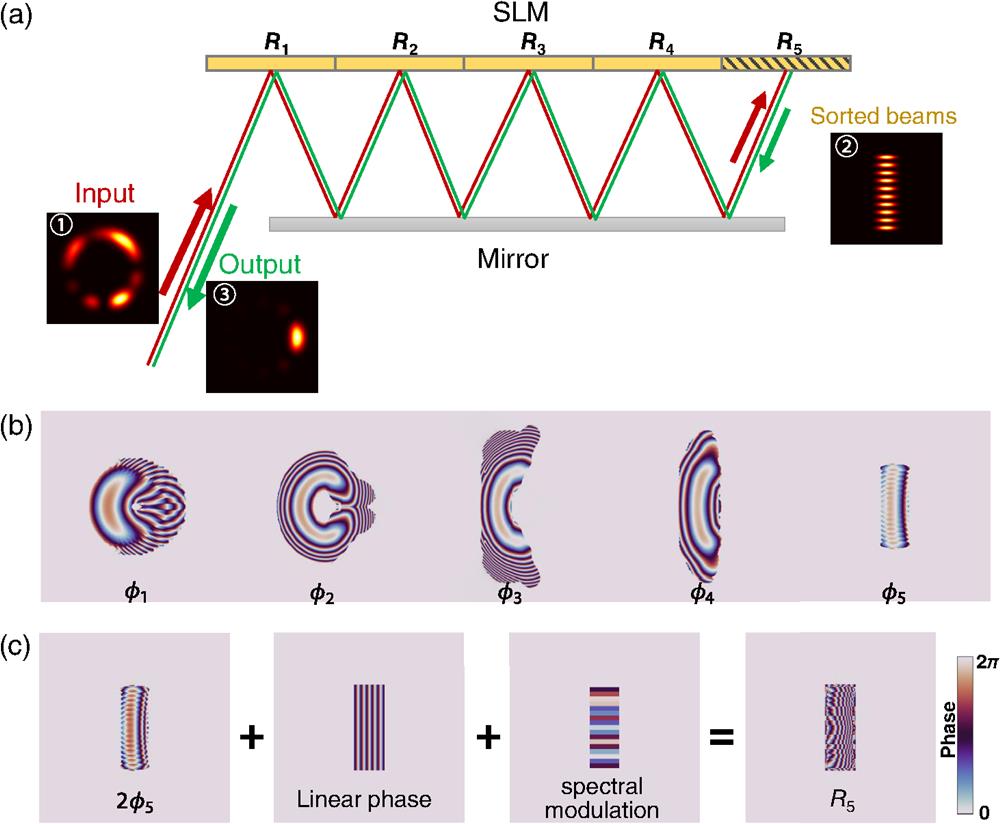
The structure of the azimuthal beam shaper is shown in Fig. 1(a). The system is compact and integrated and consists only of a reflective phase-only SLM (Holoeye GAEA-2) and a dielectric mirror. The input beam is incident from the side of the SLM, while sorting, modulation, and recombination are all realized by the phase pattern loaded on the SLM. The sorting is based on MPLC, and the only requirement for the output beams is that they are spatially separated, so that each mode could be individually modulated. We use five phase masks to transform the input OAM modes into elliptical spots array. These phase masks are inversely designed, as the algorithm describe in Note 1.1 in the Supplementary Material. Compared with the frequently used Gaussian spots, the choice of elliptical spot output reduces the high-frequency component in the phase masks. The designed phase masks are shown in Fig. 1(b), and their phase patterns are denoted as successively. The masks are equidistantly arranged on the SLM in a row, with the regions denoted as to correspondingly. The beam is modulated sequentially from to ; then the OAM mode components are sorted. Every two modulations are separated by free-space propagation in between. The separated elliptical spots are formed in . In this region, the OAM mode spectrum is modulated. At the same time, the beam is conjugated, returned along the original path, modulated by to in turn, and recombined. The input port also serves as the output port, and the beams in opposite directions are separated by a beam splitter. The multiplexing of the input port and the output port folds the volume of the system at the expense of an additional 3 dB loss.
![]()
Figure 1.Design of the azimuthal beam shaper. (a) The schematic of the system. The angular shaper consists of a phase-only SLM and a dielectric mirror. The MPLC for sorting and OAM spectral modulation and a combination of the OAM modes are implemented on the SLM. The system works in a sequence of “OAM mode sorting—mode spectral modulation—OAM mode recombination.” The input port also serves as the output port. (b) Inverse-designed phase pattern of the MPLC for transforming the coaxial OAM modes into spatially separated elliptical beams. (c) The compositions of the phase pattern of
In to , the phase modulation loaded is exactly . It is more complex for , as there are multiple functions performed in this region. The composition of the phase pattern of is shown in Fig. 1(c). At the location where each sorted spot is located, a local uniform phase is applied for modulating the phase of the OAM mode spectrum. To conjugate the beam, a phase modulation of is added, where compensates for the curved wavefront to a plane. In addition, a linear phase, which acts as a grating, is combined to make the beam return along the incident optical axis. If amplitude modulation is required, we can control the diffraction efficiency of the grating, and the unwanted power would be output from other diffraction orders and dissipated. Therefore, the system is capable of continuously modulating the complex amplitude of the OAM spectrum.
In our experiment, the dielectric mirror is parallel to the SLM and spaced 80 mm apart. The lateral spacing of the phase mask (as well as the central distance between adjacent regions) on the SLM is 3 mm, corresponding to an incident angle of 1.07 deg. Consequently, the angle of the first diffraction order of the grating in should be . The lateral spacing is determined based on the principles that the adjacent phase masks do not overlap and that the required incident angle is as small as possible. To make the results of the azimuthal beam shaping easily observable, the incident OAM beam is chosen to be perfect vortex (PV) mode, of which the radial distribution of different orders is nearly identical.25 The PV mode is ring-shaped and can be approximately expressed as at its waist, where represents the radius at its maximum light intensity, and represents the half-width of the ring. We choose and , and the PV modes or their superposition are generated by computer-generated holograms.26 The OAM modes are sorted as a column of elliptical spots in , with the vertical spacing between adjacent spots at . The elliptical spot has a Gaussian distribution in both the and directions with the expression , where and are the waist in the and directions, respectively. We choose and . The detailed experimental setup for characterization and demonstration are described in Note 2 in the Supplementary Material.
The designed MPLC supports OAM modes with topological charges of to 8 at the wavelength of 1550 nm. The insertion loss is defined as the ratio of the output optical power and the input optical power and is 15.3 dB for OAM mode , which includes 2.7 dB of scattering loss and 12.6 dB of reflection loss. The reflection loss is mainly due to the absorption of the SLM ( per bounce), which can be greatly reduced by replacing the current SLM with a high reflectivity version. The measured insertion loss for different modes is shown in Fig. 2(a), and the mode-dependent insertion loss is 3 dB, which can be further optimized by adjusting the weight of the OAM modes in the inverse design process. The mode purity is characterized by simulation. We define mode conversion loss as , where represents the overlap integral between the output mode and the ideal PV mode. As shown in Figs. 2(b) and 2(c), the conversion loss is about 1.5 dB for and (i.e., parameters used in the inverse design process). When is in the range of 600–, the conversion loss can be kept below 3 dB. It can be seen from Fig. 2(b) that the deterioration is more drastic by increasing the radius than by decreasing the radius, which is caused by the fact that the size of the PV mode with a large radius exceeds the area of phase modulation pattern. As for the tolerance for , when is in the range of 0.4–0.8, the mode conversion loss is below 3 dB. Though the MPLC is designed for PV modes with specific radius and radius-width ratio, it exhibits a high error tolerance for these two parameters.
![]()
Figure 2.Characterization of the azimuthal beam shaper. (a) The insertion loss for each OAM mode. (b) The variation of the mode conversion loss with radius of the incident beam
2.2 Functionality Demonstration
In this section, we experimentally demonstrate various functions of the proposed azimuthal field shaper. According to the translation property of the Fourier transform, a linear phase modulation on the OAM mode spectrum results in a rotation of the beam. As shown in Fig. 3, by applying a linear phase on the OAM spectrum, we rotate a petal-like beam at an interval of across azimuthal space. The original petal-like beam is the superposition of the OAM modes with a Gaussian mode spectral envelope , where represents the complex amplitude of the order OAM mode. In Fig. 3(a), the adjacent OAM modes are out-of-phase, therefore a petal-like beam is formed in . For each column, a linear phase of is applied to the mode spectrum, where denotes the rotation angle (see Note 1.2 in the Supplementary Material). The column represents the output beam without spectral modulation. The input/output intensity profiles are recorded by a camera located at 35 cm away from the input/output port. The experimental results are consistent with the simulation, except for some aberrations due to experimental errors. In contrast, the original OAM spectrum in Fig. 3(b) is in phase, and the rotation starts from . Compared with the previous case, the aberration becomes larger both in simulation and experiment. This is due to the asymmetric phase pattern of the designed MPLC, as there are more high-frequency components in the azimuthal angle of than those in the azimuthal angle of , especially for and . Traditionally, a Dove prism would be used for beam rotation. In comparison, a Dove prism has the side effect of changing the polarization,27,28 while the azimuthal beam shaper does not change the polarization state of the beam when modulating and is programmable so that no mechanical unit is needed when switching the rotation angle.
![]()
Figure 3.Demonstration of rotation of the beam with linear phase applied to the OAM mode spectrum. (a) Rotation of a petal-like beam with an OAM mode spectrum of
Based on the Talbot self-imaging effect in azimuth, the azimuthal beam shaper can act as a beam splitter or combiner. The azimuthal Talbot effect suggests that when a beam is modulated with Talbot phase on its OAM mode spectrum, the intensity of the beam would be self-imaged in the azimuth, with arbitrary azimuthal repetition-rate multiplication.17 As shown in Fig. 4(a), by periodically applying the second Talbot phase or the third Talbot phase (see Note 1.2 in the Supplementary Material), the beam undergoes self-imaging and is split into two or three beams in azimuth, respectively. The input beam is the same as that in Fig. 3(a). Note that for twofold splitting, an additional linear phase of is superimposed to avoid a high-frequency component at the of the phase mask, and thus the split beams are located at and in azimuth. For threefold self-imaging, the split beam locates at the , , and . As previous work directly generates azimuthal self-imaged beam by spatial complex amplitude modulation,17 this work is more self-consistent in realizing the azimuthal Talbot effect by means of OAM mode spectrum modulation. In addition, this can be combined with the OAM spectrum Talbot effect,29 which is the dual process of the azimuthal Talbot effect, to realize the generalized Talbot effect of OAM modes.
![]()
Figure 4.Demonstration of the beam splitting and combining with Talbot phase applied to the OAM spectrum. (a) The initial beam is split into two or three beams as a result of twofold or threefold Talbot self-imaging in azimuth. (b) Combination of two beams by an inverse process of twofold self-imaging. (c) Combination of three beams by an inverse process of threefold self-imaging.
The inverse process of the Talbot self-imaging effect can be used for the coherent combination of beams. As shown in Fig. 4(b), the initial OAM mode spectrum of the incident light has a periodic phase of , and the intensity distribution appears as two petals in the azimuth. By applying an inverse phase of , the two spots can be merged. The additional linear phase rotates the merged spot to the as well. Similarly, Fig. 4(c) shows the inverse of the threefold Talbot self-imaging process, which achieves the merging of three spots. For arbitrary input beams, the beam combining could also be implemented by modulating the OAM mode spectrum to a uniform or linear phase. This azimuthal coherent beam combining method would be suitable for multiple beams arranged in a ring, such as the output from a multicore single-mode fiber.30
The azimuthal beam shaper is also capable of amplitude modulation, and we demonstrate OAM mode spectrum filtering. In the previous demonstration, the linear phase (i.e., the grating) is added to invert the optical axis of the beam and is applied to all OAM modes. If the linear phase for some OAM modes is eliminated, these OAM modes would exit from the other port and dissipate. Therefore, these orders would be removed from the output OAM mode spectrum. Figure 5(a) shows the case that the gratings are preserved only for even-order OAM modes , and the odd-order OAM modes are filtered out. The incident beam is the same as in Fig. 3(a). Due to the widening of the spectral spacing, the recombined output beam forms a two-petal shape. Phase modulation is also employed in conjunction with the amplitude modulation to show the capability of complex amplitude modulation. We apply a spectral linear phase of that rotates the output beam at an angle of , and therefore the two output petals locate at and , respectively. In comparison with the state-of-the-art OAM mode manipulator that directly blocks the specific mode spectrum components,22 this work demonstrates programmable complex amplitude modulation of the OAM mode spectrum for the first time, we believe. Continuous amplitude modulation can be achieved by controlling the efficiency of the first diffraction order of the grating, such as by changing the modulation depth.31 This can be potentially used for power equalization of the OAM mode channels in mode-division multiplexing communication systems.
![]()
Figure 5.Demonstration of the OAM mode spectrum filter. (a) By controlling the region of grating, the odd-order OAM modes are filtered out and the even-order OAM modes are preserved. The amplitude modulation is conjunction with a linear phase modulation. (b) OAM mode with
Similarly, Fig. 5(b) shows the case that the OAM mode with is preserved. Although the output three-petal intensity distribution is similar to that of the threefold Talbot self-imaging, the self-imaging requires phase modulation only and is thereafter lossless, while the filtering process is always accompanied by an energy loss. While some modes are dropped from the region where the grating is eliminated, the modes can be added by incident in the same region with an inverse optical axis. In this way, the azimuthal beam shaper acts as an add-drop multiplexer for OAM modes.32,33
3 Conclusion
To sum up this work, we propose an azimuthal beam shaper that is capable of shaping the beam in azimuth by modulating in its Fourier domain, the OAM mode spectrum. The system is compact, consisting of only an SLM with MPLC deployed and a dielectric mirror. Both amplitude modulation and phase modulation on the mode spectrum are enabled, and multiple functionalities are experimentally demonstrated, including beam rotation, beam splitting/combining based on the azimuthal Talbot effect, and OAM mode spectrum filtering. This technique can be potentially used for coherent beam combining in laser processing, or acts as a power equalizer or an add-drop multiplexer in mode-division multiplexing communications. This work thus provides a compact and programmable solution for modulating the OAM mode spectrum and shaping beams in azimuth.
To further improve the performance and broaden the applications, the phase masks with high reflectivity could be utilized to reduce the insertion loss, and a greater number of phase masks could contribute to achieving higher mode conversion efficiency. Moreover, upgrading from the use of the OAM mode basis to a spatial orthogonal and complete basis, such as the Laguerre–Gaussian mode basis or Hermite–Gaussian basis, can facilitate the generalized shaping of the 2D beam profile. In addition, the strategy developed in this work could be seamlessly integrated with real-time OAM spectrum measurement methods,34
Biographies of the authors are not available.
References
[4] H. Rubinsztein-Dunlop et al. Roadmap on structured light. J. Opt., 19, 013001(2016).
[5] A. Forbes, M. de Oliveira, M. R. Dennis. Structured light. Nat. Photonics, 15, 253-262(2021).
[7] A. W. Lohmann et al. Array illuminator based on phase contrast. Appl. Opt., 27, 2915-2921(1988).
[12] R. W. Gerchberg, W. O. Saxton. A practical algorithm for the determination of plane from image and diffraction plane pictures. Optik, 35, 237-246(1972).
[22] L. Li et al. Photon total angular momentum manipulation. Adv. Photonics, 5, 056002(2023).
[24] N. K. Fontaine et al. Laguerre-Gaussian mode sorter. Nat. Commun., 10, 1865(2019).
[28] I. Moreno. Jones matrix for image-rotation prisms. Appl. Opt., 43, 3373-3381(2004).

Set citation alerts for the article
Please enter your email address
© Copyright 2018-2021 | Chinese Laser Press. All Rights Reserved 沪ICP备15018463号-20