Abstract
We experimentally compare the output abilities of lightly and heavily doped Ti:Sapphire (Ti:S) amplifiers with diameters as large as 150 mm. Although a lightly doped Ti:S is more favorable to overcome parasitic lasing (PL) and transverse amplified spontaneous emission (TASE), the self-phase-modulation (SPM) effect becomes more pronounced when a longer crystal is used. Recompression of the amplified, stretched pulses can be seriously affected by the SPM effect. We then propose a temporal multi-pulse pump scheme to suppress PL and TASE in a thin, heavily doped Ti:S crystal. This novel temporal multi-pulse pump technique can find potential applications in 10 PW chirped-pulse amplification laser systems.In recent years, petawatt femtosecond-class lasers based on the chirped-pulse amplification (CPA) technique have been routinely realized in many laboratories and companies globally[1–7]. Compared with the optical parametric CPA (OPCPA) technique, the CPA technique, particularly when using Ti:sapphire (Ti:S) CPA systems, has a number of important advantages, such as higher stability and efficiency as well as lower requirements for the pump laser. The CPA technique is thought to be on the verge of maturing to achieve outputs of several petawatts and even 10 PW laser pulse outputs. As a single-beamline prototype for the extreme light infrastructure (ELI) project, the APOLLON 10 PW facility in progress aims to generate a pulse of 150 J/15 fs with a power of 10 PW based on the Ti:S CPA technique[5,8]. A new project, the Shanghai Super-Intense Ultrafast Laser Facility (SULF), which plans to launch a pulse of 280 J/28 fs with a 10 PW output in 2018, is also being designed using the Ti:S CPA technique.
To achieve a peak power of several petawatts or even 10 PW of output from a Ti:S CPA laser system, crystals with a diameter in the range of 150–220 mm are necessary for the final amplification stage. Nevertheless, the main limitation that arises when designing such large-aperture, high-gain amplifiers is the restriction on the pump energy storage and signal energy extraction imposed by parasitic lasing (PL)[9,10] and transverse amplified spontaneous emission (TASE)[11]. In this work, we experimentally compare the output ability of lightly doped and heavily doped Ti:S with diameters as large as 150 mm. Our research results indicate that lightly doped Ti:S is more favorable to overcoming the PL and TASE. However, we show, by numerical simulation, that for an amplifier operating near gain saturation, self-phase-modulation (SPM) may become more pronounced when a longer crystal is used. Recompression of the amplified, stretched pulses can be seriously affected by the SPM effect. We then present a novel method called a temporal multi-pulse pump technique to overcome the PL and TASE when a heavily doped thin crystal is used.
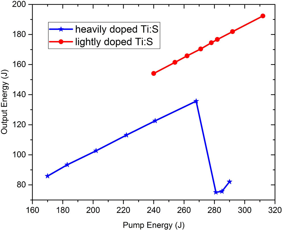
The CPA experimental setup is the same as that in Ref. [4]. Here, we compare the output performance of two different doped Ti:S crystals in the final amplification stage. One is a lightly doped Ti:S crystal with 92.6% pump light absorption, and the other is a heavily doped Ti:S crystal with 95.3% pump light absorption. The Ti:S crystal is two end pumped by a home-built Nd:glass laser system that has a 15 ns full width at half-maximum (FWHM) and approximately 26 ns for 1/e2 full width. The maximum output energy of each channel is approximately 200 J at 527 nm. The injection energy is maintained at 35 J in each case. To suppress the PL and TASE in the final amplifier, we used Cargille Series M refractive index liquid doped with an absorber (IR 140) as the cladding material. Meanwhile, we carefully optimized the seed-pump time delay to obtain a maximum output in each case. The amplified output energy with respect to the pump energy under an optimized time delay in each case is shown in Fig. 1. For the lightly doped Ti:S, the maximum output energy was 192.3 J. By contrast, we only obtained an output of only 135.7 J output from a heavily doped Ti:S. It was also found that the output ability of the lightly doped Ti:S was less sensitive to the seed-pump delay than the heavily doped Ti:S.
Sign up for Chinese Optics Letters TOC. Get the latest issue of Chinese Optics Letters delivered right to you!Sign up now

Figure 1.(Color online) Output energy with respect to pump energy; heavily doped Ti:S case (blue line) and lightly doped Ti:S case (red line).
The experimental results show that lower titanium concentrations and longer crystal lengths are preferred to suppress PL to some extent. It is well known that in order to efficiently extract the stored energy from an amplifier, one must work near the saturation. In this case, the intense laser pulse experiences a time-varying phase modulation produced by the intensity variation of the pulse itself. The new nonlinear frequency chirp adds to the original linear frequency chirp of the laser pulse and distorts the recompressed pulse quality, thereby reducing the final peak power. Although it is possible to readjust the expansion or compression gratings to compensate for this effect on the average or at the peak of intensity, as there always exist some intensity modulation in the practical laser beam spot, this means that the spectral phase distortion caused by SPM variation, owing to the beam’s intensity profile, cannot be totally compensated[12]. To examine the SPM effect in strongly saturated CPA systems, we conduct numerical simulation according to the model described in Ref. [13]. The simulation considers a linear chirp laser pulse that has a Gaussian or a second-order super-Gaussian pulse shape with a 0.5 ns FWHM. In both cases, the linear chirped pulse has a 16 fs (FWHM) Fourier transform limit (TL) pulse width. The pump light absorption of the Ti:S crystal is maintained at 95.3%, while the length and the titanium concentrations of the crystal are varied. The Ti:S crystal is two end pumped. Each end pump pulse has energy of 160 J with a 120 mm diameter. The input signal is 35 J with a 115 mm diameter. The signal is injected into the Ti:S when half of the pump energy is absorbed. We assume that the initial linear chirp and material dispersion can be canceled exactly. Then, we focus on the effect of SPM on compressed pulse quality.
The simulation result is shown in Fig. 2. The red lines in Figs. 2(a) and 2(c) indicate the compressed pulse width evolution versus the crystal length for a Gaussian pulse shape and second-order super-Gaussian pulse shape, respectively. FWHM and root-mean-square (RMS) pulse widths are shown. For the relatively short crystal length, the spectral broadening of the pulse that is caused by the SPM effect in the amplifier makes the FWHM of the compressed pulse slighly shorter than the initial TL pulse width. As the crystal length increases, the FWHM of the compressed pulse broadens and cannot be compressed to its initial TL pulse width. The RMS pulse width is monotonously increased with the crystal length because it has sensitivity to the energy in the wings of a pulse. The blue lines in Figs. 2(a) and 2(c) indicate the B-Integral of the peak intensity to measure the nonlinear phase shift of the laser pulse. The blue lines exhibit an almost linear increase with the crystal length. Figures 2(b) and 2(d) show the intensity profiles of compressed pulses for chirped Gaussian pulses and second-order chirped super-Gaussian pulses, respectively. The SPM effect plays an important role in determining the final shape of the compressed pulse, even at relatively low values of the cumulative B-integral, [14]. Changes in the compressed pulse shape are clearly shown in Figs. 2(b) and 2(d). A pedestal is generated during the final pulse compression because the gratings compress only the original frequency chirp, and the new frequency chirp from SPM spreads out as a low intensity pedestal, owing to different group velocity dispersion. The new frequency chirp determines the width of the pedestal, while the energy associated with the pedestal is determined by the fraction of the pulse energy near the sharp change in its temporal envelope[13]. For a super-Gaussian pulse of high order, SPM occurs near sharply rising or falling edges of the chirped pulse. Owing to the group velocity difference of the initial linear chirp and new nonlinear chirp in grating pairs, the pre-pulse and post-pulse forms. For a Gaussian pulse, although the added frequency chirp may be smaller than that of a super-Gaussian pulse, a much larger amount of energy is involved within the region of large slope of intensity I(t) or large , leading to a relatively high pedestal.
Figure 2.(Color online) Compression pulse width and B-Integral evolution versus crystal length for (a) Gaussian pulse shape and (c) second-order super-Gaussian pulse shape. Normalized intensity profile of compressed pulse for (b) Gaussian pulse shape and (d) second-order super-Gaussian pulse shape.
In order to alleviate the SPM effect by using thin heavily doped Ti:S crystals, studies on finding new methods for suppressing PL and TASE are necessary. Currently, there are two major techniques for resolving PL and TASE. One method is to decrease the Fresnel reflection from the crystal perimeter by applying index-matched material, which leads to a higher threshold of PL. The other method is to adjust the temporal delay between the signal pulse and pump pulses. This is known as the extraction during pumping (EDP)[11] technique. In this method, only part of the pump energy is stored in the gain medium before the arrival of the input signal, after which a large part of the energy stored in the crystal is quickly transferred to the signal pulse as it is amplified. This results in the transverse gain remaining low. The remaining pump pulses keep pumping for the next pass of the amplified signal pulse. A new scheme is proposed by using a temporal dual-pulse pump[15]. The suggested dual-pulse pump has a complex temporal profile, a relatively short and high-energy first pulse and a relatively long and low-energy second pulse.
We present a new method that uses a temporal multi-pulse pump beam to suppress PL and TASE. Rather than the relatively complex temporal profile proposed in Ref. [15], here, each pump pulse temporal profile is identical, while the energy of each pump pulse is different. This corresponds to the practical situation where one high-energy pump pulse is divided into multiple, individual pulses using beam splitters (BS0 to BS4), as shown in Fig. 3(a). We can control the transverse gain in the entire amplification stage by optimizing the pump energy distribution, which can also be done conveniently by choosing beam splitters with different splitting rations. We adjust the optical path difference to set an appropriate time delay between each of the individual pump pulses.
Figure 3.(a) Multi-pulse pump generation. (b) Schematic of three-pulse pump scheme. (c) Signal-pump time-delay control.
Figure 3(c) shows the signal-pump time-delay control. In a four-pass amplification, we assume Ep1-1 and Ep2-1 are absorbed in the first stage, Ep1-2 and Ep2-2 are absorbed in the second stage, and Ep1-3 and Ep2-3 are absorbed in the third stage. The Ti:S crystal is double-end pumped, and there are three pulses at each end, as shown in Fig. 3(b). We also assume the input signal passes through the Ti:S crystal from face 1, which is the same side of Ep1-1, Ep1-2, and Ep1-3. The splitting ratios of the beam splitters are crucial, because they determine the pump energy distribution throughout the entire amplification stage. The pump energies of Ep1-1 and Ep2-1 should be relatively large to ensure adequate gain amplification in the first stage. However, since the input signal energy is low before the first pass through the Ti:S crystal, after the first-pass amplification, there remains a large degree of inversion population. The pump pulses of Ep1-2 and Ep2-2 should refuel the consumed stored energy in the first stage, while avoiding overdriving the gain medium. Since the signal pulse has a lower energy and consumes a smaller inversion population at the crystal entrance face than at the exit face, Ep1-2 is smaller than Ep2-2. Since the energy of the signal pulse before the second pass through the Ti:S crystal is relatively large, a large amount of the inversion population is converted into signal energy. The pump pulse of Ep1-3 and Ep2-3 then continues pumping the gain medium to prepare for the third-pass amplification stage. In this temporal multi-pulse pump scheme, the output from a large-aperture CPA Ti:S amplifier is immune from the signal-pump time-delay jitter, as the pump energy distribution is constrained mainly by means of the beam splitters.
Figure 4(a) shows the numerical calculation of the transverse gain of the two faces of a heavily doped Ti:S crystal in each stage of a four-pass amplification. , shown in Fig. 4, is the transverse gain of face before the signal time passes though the Ti:S crystal in the four-pass amplification process. The parameters of the Ti:S crystal are the same as those used in the experiment with a 27.3 mm length and 95.3% pump light absorption. The splitting ratios of the beam splitters used in the numerical simulation are shown in Fig. 3(a). They are optimized when pump energy is 320 J. As shown in Fig. 4(a), when the pump energy is 320 J, each has the same value. Even when pump energy deviates from 320 J, the transverse gain of the two faces in each stage is comparable. This means that the processing load is shared throughout the entire four-pass amplification process. For comparison, Fig. 4(b) shows the results when a traditional one-pulse pumped scheme is used. We numerically simulate the transverse gains of the two crystal faces before the signal passes through the Ti:S crystal in each stage of the four-pass amplification under different signal-pump time delays. In this case, a dramatic change occurs in for any given time delay. This indicates an unreasonable pump energy distribution, because the processing load is concentrated in one stage, while it is overly relaxed in the other stage.
Figure 4.(Color online) (a) Transverse gain and amplified energy with respect to pump energy. (b) Transverse gain under different time delay in traditional one-pulse pump scheme.
The three-pulse pump scheme proposed above can be easily extended to a four-pulse pump scheme. However, in this case, the spatial arrangement of the pump pulses may be constrained. It is favorable to make the pump pulses propagate in the same line. Since the Ti:S amplification is sensitive to the pump light polarization state, a traditional polarization beam combination scheme is inappropriate. Figure 5 shows a possible scheme. Two 1053 nm laser pulses with horizontal polarization and vertical polarization are combined in the same line using a polaroid. The polarization state of these two 1503 nm laser pulses are rotated 45° simultaneously by using a quartz polarization rotator. These two 1053 nm laser pulses are then frequency doubled in a KDP crystal using Type-II second-harmonic generation (SHG). The generated 526.5 nm laser pulses have the same polarization state and can be used to pump the Ti:S crystal. In spite of that, it is only possible to optimize the SHG conversion efficiency of one input pulse energy, while the conversion efficiency of the other pulse is not optimal; in this way, two time-separated pump laser pulses with the same polarization state can propagate in the same line, leading to a more compact structure.
Figure 5.Schematic of beam combination of two time-separated pump laser pulses with the same polarization state.
In conclusion, we experimentally compare the output ability of lightly doped and heavily doped Ti:S with a diameter as large as 150 mm. Although lightly doped Ti:S is more favorable to overcome PL and TASE and to obtain a larger amplified energy, the SPM effect becomes serious when a longer crystal is used. SPM will ultimately limit the peak power and the pulse contrast achievable on recompression, even at relatively low values of the cumulative B-Integral, . To alleviate the SPM effect by using a thin, heavily doped Ti:S crystal while suppressing PL and TASE, a new multi-pump scheme is proposed. The numerical simulation results confirm the effectiveness of this new scheme. Meanwhile, a beam combination method is proposed to solve the spatial arrangement of pump pulses in a temporal multi-pulse pump scheme. This novel temporal multi-pulse pump technique has potential applications in 10 PW CPA laser systems.
References
[1] K. Ertel, C. Hooker, S. J. Hawkes, B. T. Parry, J. L. Collier. Opt. Express, 16, 8039(2008).
[2] T. J. Yu, S. K. Lee, J. H. Sung, J. W. Yoon, T. M. Jeong, J. Lee. Opt. Express, 20, 10807(2012).
[3] Y. X. Chu, X. Y. Liang, L. H. Yu, Y. Xu, L. Xu, L. Ma, X. M. Lu, Y. Q. Liu, Y. X. Leng, R. X. Li, Z. Z. Xu. Opt. Express, 21, 29231(2013).
[4] Y. Chu, Z. Gan, X. Liang, L. Yu, X. Lu, C. Wang, X. Wang, L. Xu, H. Lu, D. Yin, Y. Leng, R. Li, Z. Xu. Opt. Lett., 40, 5011(2015).
[5] D. N. Papadopoulos, J. P. Zou, C. L. Blanc, G. Cheriaux, P. Georges, F. Druon, G. Mennerat, P. Ramirez, L. Martin, A. Freneaux, A. Beluze, N. Lebas, P. Monot, F. Mathieu, P. Audebert. High Power Laser Sci. Eng., 4, e34(2016).
[6] V. Bagnoud, F. Wagner. High Power Laser Sci. Eng., 4, e39(2016).
[7] C. Danson, D. Hillier, N. Hopps, D. Neely. High Power Laser Sci. Eng., 3, -e3(2015).
[8] J. P. Zou, C. L. Blanc, D. N. Papadopoulos, G. Cheriaux, P. Georges, G. Mennerat, F. Druon, L. Lecherbourg, A. Pellegrina, P. Ramirez, F. Giambruno, A. Freneaux, F. Leconte, D. Badarau, J. M. Boudenne, D. Fournet, T. Valloton, J. L. Paillard, J. L. Veray, M. Pina, P. Monot, J. P. Chambaret, P. Martin, F. Mathieu, P. Audebert, F. Amiranoff. High Power Laser Sci. Eng., 3, -e2(2015).
[9] F. G. Patterson, J. Bonlie, D. Price, B. White. Opt. Lett., 24, 963(1999).
[10] X. Y. Liang, Y. X. Leng, C. Wang, C. Li, L. H. Lin, B. Z. Zhao, Y. H. Jiang, X. M. Lu, M. Y. Hu, C. Zhang, H. Lu, D. Yin, Y. Jiang, X. Lu, H. Wei, J. Zhu, R. Li, Z. Xu. Opt. Express, 15, 15335(2007).
[11] V. Chvykov, J. Nees, K. Krushelnick. Opt. Commun., 312, 216(2014).
[12] O. A. Konoplev, D. D. Meyerhofer. IEEE J. Sel. Top. Quantum Electron., 4, 459(1998).
[13] Y. H. Chuang, L. Zheng, D. D. Meyerhofer. IEEE J. Quantum Electron., 29, 270(1993).
[14] M. D. Perry, T. Ditmire, B. C. Stuart. Opt. Lett., 19, 2149(1994).
[15] Y. Chu, X. Liang, L. Yu, L. Xu, R. Li, Z. Xu. Opt. Commun., 318, 67(2014).