In this paper, we report on the performance comparison of all-optical signal processing methodologies to compensate fiber transmission impairments, namely chromatic dispersion and nonlinear distortion caused by the Kerr effect, in a coherent 112 Gbit∕s dual-polarization 64 bit quadrature amplitude modulation system over 800 km standard single-mode fiber. We numerically compare optical backward propagation (OBP) with optical phase conjugation (OPC) techniques, namely. mid-link spectral inversion, predispersed spectral inversion, and OPC with nonlinearity module. We also evaluate a self-phase-modulation-based optical limiter with an appropriate prechirping to compensate for the intensity fluctuations as a hybrid approach with OBP. The results depict improvement in system performance by a factor of ~4 dB of signal input power by all-optical signal processing methods, which is comparative with ideal digital backward propagation where the high complexity is the intrinsic impediment in the real-time implementation of the technique with coherent receivers.
Digital compensation of linear and nonlinear signal distortions with a backward propagation algorithm (DBP) is a topic of high interest in recent months to improve the nonlinear tolerance of the optical communication systems. With higher baud rates and advanced modulation formats, channel capacity [1,2] is limited by the signal degradation due to fiber nonlinearity as it increases with signal input power. The DBP algorithm allows joint compensation of chromatic dispersion (CD) and nonlinearities (NL) [3–6] along with the coherent receiver. It can be implemented by inversely solving the nonlinear Schrödinger equation (NLSE) using a split-step Fourier method (SSFM). It is demonstrated that DBP in a single-channel transmission can be improved by using a modified split-step Fourier method (also termed as modified DBP) [7,8]. M-DBP is based on the optimization of the nonlinear calculation point. In order to reduce the complexity of the algorithm, the correlated DBP (CBP) algorithm is introduced in [9,10]. The performance of the DBP algorithm is evaluated for diverse baud rates, namely 14, 28, and 56 Gbaud with quadrature phase shift keying modulation formats [11–14]. Especially with the introduction of the logarithmic step-size-based DBP algorithm [12–14], which shows efficient system performance as compared to M-DBP, the nonlinear threshold point (NLT) of higher baud rate transmissions is significantly improved. Due to exponentially growing global bandwidth demand, polarization-division-multiplexed (PDM) 16-state quadrature amplitude modulation (16-QAM) with high spectral efficiency (SE) is becoming a promising candidate to achieve per-channel bit rates beyond and has been the subject of extensive research [15–19]. The multichannel transmission performance over 670 km single-mode fiber (SMF) and 656 km large effective area pure-silica-core fiber is reported in [16,17]. The evaluation of the DBP algorithm in a PDM 16-QAM system over 250 km of SMF with uncompensated link is reported in [19], with 3.5 dB of -improvement in the performance.
However, this high SE is obtained at the expense of complicated transmitter and receiver structures, higher optical signal-to-noise ratio requirements, and dense constellation diagrams, which collectively make them less robust against fiber transmission impairments, namely CD and NL. But also the complexity of DBP algorithm is so high due to ultrawide bandwidth requirements that it becomes an intrinsic impediment in the real-time implementation of the DBP algorithm.
To overcome the computational complexities of DBP in higher order modulation formats such as 32-QAM and more, an alternative approach of optical backward propagation (OBP) is proposed [20]. The OBP module consists of dispersion compensating fiber (DCF) and a NL compensator (NLC). In the NLC module of the OBP, an effective negative Kerr nonlinear coefficient using two highly nonlinear fibers (HNLFs) is realized. It is a well-known fact that in the all-optical signal processing techniques intensity fluctuation is a critical issue [21]. Till date, numerous techniques for optical intensity stabilization including optical limiters, optical reshaping techniques, and optical regenerators have been evaluated [22,23]. Recently, the methods based on optical phase conjugation (OPC) with NL module (OPC-NM) [24] and predispersed spectral inversion (PD-SI) [25] have been investigated in order to attain comparative system performance with respect to ideal DBP.
Sign up for Photonics Research TOC. Get the latest issue of Photonics Research delivered right to you!Sign up now
In this paper, we have extended our previously reported work [26] and numerically implemented various all-optical signal processing methods for the joint compensation of CD and NL. These methods are fundamentally divided in to two main types: OBP and OPC. The performance of OBP is compared with OPC techniques, namely mid-link spectral inversion (MLSI), OPC-NM, and PD-SI, and both are compared with ideal DBP in terms of system performance in DP-64-QAM transmission over an 800 km SMF link. The ideal DBP algorithm is implemented with 40 calculation steps per fiber span [25]. We have also evaluated an self-phase modulation (SPM)-based all-optical intensity limiter (IL) [23] as a hybrid approach with OBP. This all-optical method is evaluated at the transmitter (Tx), termed as IL-OBP (Tx) and as an in-line module in the fiber link (FL), termed as IL-OBP(FL).
2. MATHEMATICAL DESCRIPTION OF PROPAGATION OF OPTICAL SIGNALS
The propagation of optical signals in SMF can be interpreted by Maxwell’s equations. It can mathematically be given in the form of a wave equation as in Eq. (1) [27]: where is the electric field, is the vacuum permeability, is the speed of light, and is the polarization field. At very weak optical powers, the induced polarization has a linear relationship with such that where is the vacuum permittivity and is the first-order susceptibility. To consider NL in the system, Eq. (2) can be rewritten as in Eq. (3) [27]: whereas is the nonlinear part of polarization. Equation (3) can be used to solve Eq. (1) to derive the propagation equation in nonlinear dispersive fibers with few simplifying assumptions. First, is treated as a small perturbation of and the polarization field is maintained throughout the whole propagation path. Another assumption is that the index difference between the core and cladding is very small and the center frequency of the wave is assumed to be much greater than the spectral width of the wave, which is also called the quasi-monochromatic assumption. The quasi-monochromatic assumption is analogous to low-pass (LP) equivalent modeling of bandpass electrical systems and is equivalent to the slowly varying envelope approximation in the time domain [27]. Finally, the propagation constant, , is approximated by the few first terms of a Taylor series expansion about the carrier frequency, , that can be given as where
The second-order propagation constant, , accounts for the group velocity dispersion effects in the optical fiber communication systems. Depending on the sign of , the dispersion region can be classified into two parts as normal () and anomalous (). Qualitatively, in the normal-dispersion region, the higher frequency components of an optical signal travel slower than the lower frequency components. In the anomalous dispersion region it occurs vice versa. Fiber dispersion is often expressed by , which is called a dispersion parameter. is defined as and the mathematical relationship between and is given in [27] as where is the wavelength of the propagating wave and is the group velocity. The cubic and the higher order terms in Eq. (4) are generally negligible as long as the quasi-monochromatic assumption remains valid. However, when the center wavelength of an optical signal is near the zero-dispersion wavelength (i.e., ), as for broad spectrum of the signals, then the terms should be included.
If the input electric field is assumed to propagate in the direction and is polarized in the direction, Eq. (1) can be rewritten as [27] where is the varying slowly envelope of the electric field, is the propagation distance, ( is physical time; is the group velocity at the center wavelength), is the fiber loss coefficient [], is the second-order propagation constant [], is the third-order propagation constant [], is the nonlinear refractive coefficient [], is the nonlinear index coefficient, is the effective core area of the fiber, is the center wavelength, and is the central angular frequency. The nonlinear refractive index is a material parameter related to the third-order susceptibility. When the pulse width is greater than 1 ps, Eq. (7) can further be simplified because the Raman effects and self-steepening effects are negligible compared to the Kerr effect [27]. Mathematically, the generalized form of the NLSE suitable to describe the signal propagation in communication systems can be given as Also note that and are termed linear and nonlinear operators as
A. DBP
The NLSE can be solved inversely to calculate the undistorted transmitted signal from the distorted received signal. This operation is equivalent to passing the received signal through a fictitious fiber having opposite-signed parameters. It is also possible to perform backward propagation at the transmitter side by predistorting the signal to invert the channel and then transmitting the predistorted waveform. In the absence of noise, both schemes are equivalent. We shall focus on receiver-side DBP. The mathematically inverse NLSE can be given as where and are the linear and nonlinear operators, respectively.
The performance of the DBP algorithm mainly depends on the solution of the propagating parameters of NLSE. To numerically solve NLSE with high accuracy, SSFM is used as discussed in the previous section. Both the operators, namely linear and nonlinear , are solved separately; the linear part is solved in the frequency domain whereas nonlinear is solved in the time domain. This DBP model can be implemented on both the transmitter side and the receiver side. When the signal is numerically distorted at the transmitter by the DBP algorithm and then this predistorted signal is transmitted through the FL, it is termed transmitter-side DBP. In the majority of cases DBP is implemented along with the coherent receiver, termed receiver-side DBP. In the absence of noise in the transmission link both the schemes of DBP are equivalent. As the backward propagation operates on the complex envelope of , this algorithm in principle is applicable with any modulation format of the transmission. It should be noted that the performance of DBP is limited by the amplified spontaneous emission noise as it is a nondeterministic noise source and cannot be backpropagated. DBP can only take into account the deterministic impairments. In terms of step size , DBP can be categorized in three types: (1) subspan step size, in which multiple calculation steps are processed over a single span of fiber; (2) per-span step size, which is one calculation step per fiber span, and (c) multispan step size, in which one calculation step is processed over several spans of fiber. These methods to implement DBP are of utmost importance as the complexity of the DBP algorithm is the key for its future real-time implementation in coherent transmission. Especially with advanced higher order modulation formats and bit rates, the high complexity is the intrinsic impediment in the real-time implementation and is a topic of high interest these days.
B. OPC
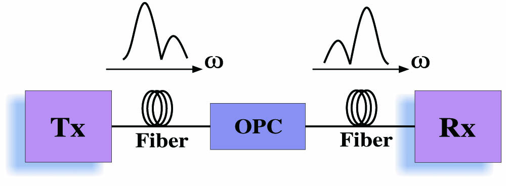
OPC, also known as the SI technique, is a method to compensate the Kerr NL and CD [26]. A simplified design of the transmission link with no optical DCF, in-line amplifiers, and OPC is shown in Fig. 1. Since the CD accumulates along the transmission line, resulting effectively in the absence of a periodic in-line dispersion map, OPC efficiently compensates CD in such schemes without the extra insertion loss of the DCF modules.
The basic principle of OPC is that the pump frequency and the signal frequency beat together to generate a new frequency , such that , which has the spectrum reversed with respect to the input signal. By filtering and amplifying the output field, the conjugated signal can be extracted and propagated along the second half of the span. As a result, the pulse chirp is reversed and the effect of the fiber dispersion can be compensated for. Thus, in a transmission link with the same fiber before and after the OPC, full group velocity dispersion compensation is obtained by placing the OPC at the mid-link.
3. NUMERICAL MODEL AND SIGNAL PROCESSING TECHNIQUES
Figure 2(i) illustrates the numerical model of single-channel dual-polarization (DP-) 64-QAM transmission system. The data stream consists of a pseudo-random binary sequence. To simplify our numerical analysis, we neglect the effect of polarization mode dispersion (PMD). The signals are transmitted over SMF () with physical parameters of dispersion , nonlinear coefficient and attenuation constant . No in-line optical DCF is used to compensate the CD. Erbium-doped fiber amplifiers (EDFAs) are modeled with 16 dB of gain and 4.5 dB of noise figure. A homodyne coherent polarization and phase diversity receiver is used. The signal is sampled at two samples per symbol and passed on to the digital signal processing (DSP) module. The DSP module is numerically implemented after the coherent detection with the help of MATLAB vR2011b. When the CD is digitally compensated [electronic dispersion compensation (EDC)], finite impulse response (FIR) filters are used (-spaced taps) and are adapted using a least mean square algorithm. An antialiasing second-order LP Gaussian filter is also used at the receiver. The sampled signal goes through the DSP module having adaptive polarization demultiplexing, which is realized by an FIR butterfly equalizer using the constant-modulus algorithm. It is assisted by the phase error estimation module based on the Viterbi–Viterbi algorithm, which is able to remove small residual constellation rotations.
Figure 2.(i) Numerical model of DP-64-QAM coherent transmission [PBS: polarization beam splitter, PBC: polarization beam combiner]; (ii) OPC-NM module; (iii) SPM-based all-optical IL; (iv) OBP module; (v) graphical representation of optical power along FL, MLSI, and PD-SI.
Figure 2(ii) shows the concept of OPC-NM containing HNLF and an OPC module. It is implemented at point (A) in the transmission link as an all-optical module for precompensating the fiber Kerr effect. The parameters of this module, namely fiber length , signal power , and nonlinear coefficient , is adjusted along with OPC module, so that it produces a negative nonlinear phase shift of , cancelling the original from the FL [24]. Moreover, EDC is also included at the receiver for OPC-NM analysis to compensate residual CD of the link. Figure 2(iii) depicts the basic module of the SPM-based all-optical IL [23], which is placed in the main transmission system at point (A) for IL-OBP(Tx) and at point (C) for IL-OBP(FL) and removed for conventional implementation of OBP [placed at point (D)]. This module consists of an EDFA, DCF, HNLF, and an optical bandpass filter (OBPF) cascaded together [23]. An amplified optical signal is passed through a DCF to add the up-chirp in the signal. The physical parameters of DCF are , and . Then the signal enters in the HNLF having the physical parameters of length , , , , and . The signals experience SPM providing spectral broadening, which maintains a constant intensity at the center wavelength because of the prechirping procedure. Finally the signals are filtered with the help of the OBPF, which is a second-order Gaussian filter. The OBP module, as illustrated in Fig. 2(iv), is implemented by using the parameters given in [20]. The length of the DCF is adjusted according to the accumulative CD in the transmission link. The combination of HNLFs, which are used to realize an effective negative Kerr nonlinear coefficient, are modeled with and for HNLF1 and and for HNLF2. The pump powers are 10 and 5.6 mW for pump1 and pump2, respectively. These physical parameters of the fiber are optimized to obtain the best transmission performance. Also the product of effective length and nonlinear coefficient is adjusted so that the nonlinear phase shift accumulated over the fiber span can be compensated.
In Fig. 2(v), the power profile along the FL and SI are given. For MLSI, SI is applied at the middle of link [at point (B)], and for PD-SI additional DCF is included equivalent to a dispersion of amplifier spacing minus the effective length to make sure that that NL occurs for similar ranges of dispersion [25]. All the numerical simulations are carried out by using Optisystems v11 and MATLAB vR2011b.
4. RESULTS AND DISCUSSION
Figure 3 depicts the performance comparison of DP-64-QAM transmission over 800 km SMF with EDC, DBP, OBP, IL-OBP(Tx), IL-OBP(FL), SI, PD-SI, and OPC-NM for a range of signal input launch powers. The power is varied from to 2 dBm. As we increase the launch power the all-optical algorithms efficiently compensate CD and NL, outperforming EDC, hence improving the NLT of the system. The performance is compared at the forward error correction (FEC) threshold level (), which corresponds to bit-error-ratio. First, we have implemented the ideal DBP algorithm (with 40 steps per fiber span) based on SSFM [6,25]. The performance of the system is improved by a factor of 4.3 dB of signal launch power, as shown in Fig. 3. Then we have evaluated the OBP module. This method gives 3.21 dB improvement in system performance as compared to EDC. The OBP method gives a penalty of as compared to DBP. This is due to the fact of DCF-induced discrepancies in OBP, while all the CD is compensated digitally in DBP. Therefore the launch power to the DCF is kept low in these numerical analysis so that the nonlinear effects in the DCF can be negligibly small.
Figure 3. factor (dB) as a function of signal input launch power in DP-64-QAM coherent transmission over 800 km SMF for diverse fiber transmission impairment compensation methods.
In order to further enhance the performance of OBP, we have implemented an SPM-based all-optical IL as a hybrid approach with OBP. Both IL-OBP(Tx) and IL-OBP(FL) are evaluated. The IL-OBP(FL) approach gives improved performance as compared to OBP. This is due to the fact that signals propagate through the transmission fiber with imperceptible amplitude fluctuations and therefore suppress the nonlinear phase noise. This approach shows transmission performance equivalent to DBP. Furthermore, we have evaluated the all-optical methods based on the principle of OPC. The DP-64-QAM transmission is spectrally inverted at the middle of transmission link (after 400 km) to realize MLSI. The system shows 1.8 dB of signal launch power improvement as compared to EDC, as shown in Fig. 3. When PD-SI is applied in the transmission link, the results depict a performance improvement of 4.28 dB. The above results show that both OPC methods outperforms EDC, while PD-SI has a performance equivalent to DBP. Also we have evaluated the transmission performance of the OPC-NM module. This method also displays efficient compensation of CD and NL and shows 4 dB of improvement in system performance. Figure 4 qualitatively depicts, in terms of constellation diagrams, the performance comparison of EDC, OBP, OPC-NM, and DBP for DP-64-QAM at 0 dBm signal launch power. As mentioned earlier, in our numerical analysis we neglect the PMD effect, which is a stochastic process, and we are emphasizing the compensation of deterministic fiber impairments, namely CD and NL. Otherwise, due to PMD, polarization-dependent loss can effect the performance of the system and it is necessary to have polarization tracking, or in other words polarization alignment between the pumps and signal in all-optical signal processing methods.
Figure 4.Constellation plots after EDC, OBP, OPC-NM, and DBP for DP-64-QAM at 0 dBm signal launch power.
Finally, we have evaluated the system performance of DP-64-QAM in terms of transmission distance achieved at signal launch power, as shown in Fig. 5. The all-optical signal processing methods, namely OBP, PD-SI, OPC-NM and IL-ONP(FL) are compared with DBP and EDC. The results are that at the FEC threshold level () the maximum transmission distance is increased to 1290 km by using DBP as compared to 800 km by processing with EDC only. We have also acquired comparative transmission distances with PD-SI (1300 km), OPC-NM (1200 km), and IL-OBP(FL) (1236 km), showing efficient compensation of CD and NL, enabling performance equivalent to that of full-precision DBP. It would also be very challenging to implement DBP for a dense wavelength-division-multiplexed system as a real-time signal processing module along with coherent receiver, since the computational effort and bandwidth required in this case would be enormous. In case of OBP, it can compensate for all the channels of a WDM system simultaneously without additional cost, provided the HNLFs are designed for wideband applications.
Figure 5.System performance at various transmission distances for DP-64-QAM at signal launch power.
To summarize, we have investigated the all-optical signal processing methods to compensate CD and NL in a DP-64-QAM system over 800 km SMF. It has been numerically demonstrated that transmission performance comparable to the DBP algorithm, where the computational efforts and bandwidth required for higher order modulation formats would be prodigious, can be attained with all-optical methods such as PD-SI, OPC-NM, and IL-OBP(FL). The results show improvement in system performance by a factor of of signal input power by all-optical signal processing methods. These numerical investigations will be helpful in deployment of scalable equalization of NL in future networks.
[7] C. Y. Lin, M. Holtmannspoetter, R. Asif, B. Schmauss. Compensation of transmission impairments by digital backward propagation for different link designs. 36th European Conference Optical Communication (ECOC), 3.16(2010).
[9] L. Li, Z. Tao, L. Dou, W. Yan, S. Oda, T. Tanimura, T. Hoshida, J. Rasmussen. Implementation efficient non-linear equalizer based on correlated digital back-propagation. Conference on Optical Fiber Communication/National Fiber Optic Engineers Conference (OFC/NFOEC), OWW3(2011).
[12] R. Asif, C. Y. Lin, M. Holtmannspoetter, B. Schmauss. Logarithmic step-size based digital backward propagation in N-channel 112 Gbit/s/ch DP-QPSK transmission. 13th International Conference on Transparent Optical Networks (ICTON), T.u.P6(2011).
[15] M. Nolle, J. Hilt, L. Molle, M. Seimetz, R. Freund. 8×224Gbit/s PDM 16QAM WDM transmission with real-time signal processing at the transmitter. 36th European Conference and Exhibition on Optical Communication (ECOC), We.8.C.4(2010).
[19] M. Mussolin, D. Rafique, J. Martensson, M. Forzati, J. Fischer, L. Molle, M. Nlle, C. Schubert, A. Ellis. Polarization multiplexed 224 Gb/s 16QAM transmission employing digital back-propagation. 37th European Conference and Exposition on Optical Communications, We.8.B.6(2011).
[26] R. Asif, M. K. Islam, M. Zafrullah. Analysis and application of scalable non-linear equalization in 112 Gbit/s DP-64QAM coherent transmission over single mode fibers. Photonics Global Conference (PGC), c12a345(2012).
[27] G. Agrawal. Fiber-Optic Communication Systems(2001).