2Chinese Academy of Sciences, Shanghai Institute of Optics and Fine Mechanics, Key Laboratory of Ultra-intense Laser Science and Technology, Shanghai, China
3Shenzhen Technology University, College of Engineering Physics, Shenzhen, China
【AIGC One Sentence Reading】:Hyperbolic mirrors effectively focus ultra-intense ultrashort lasers, achieving a tighter focal spot and higher intensity compared to other methods, beneficial for laser physics applications.
【AIGC Short Abstract】:Utilizing a rotational hyperbolic mirror after a rotational parabolic mirror effectively compresses laser pulse energy into a smaller focal spot, achieving single-wavelength size focusing. This advanced technique avoids unwanted high-intensity effects, enhancing the focused intensities of ultra-intense ultrashort lasers, crucial for laser physics applications.
Note: This section is automatically generated by AI . The website and platform operators shall not be liable for any commercial or legal consequences arising from your use of AI generated content on this website. Please be aware of this.
Abstract
Compressing all the energy of a laser pulse into a spatiotemporal focal cube edged by the laser center wavelength will realize the highest intensity of an ultra-intense ultrashort laser, which is called the λ3 regime or the λ3 laser. Herein, we introduced a rotational hyperbolic mirror—an important rotational conic section mirror with two foci—that is used as a secondary focusing mirror after a rotational parabolic mirror to reduce the focal spot size from several wavelengths to a single wavelength by significantly increasing the focusing angular aperture. Compared with the rotational ellipsoidal mirror, the first focal spot with a high intensity, as well as some unwanted strong-field effects, is avoided. The optimal focusing condition of this method is presented and the enhanced tight focusing for a femtosecond petawatt laser and the λ3 laser is numerically simulated, which can enhance the focused intensities of ultra-intense ultrashort lasers for laser physics.
Strong-field laser physics1 and ultrafast laser physics2 are currently important research areas in experimental physics. Focused intensity, rather than unfocused peak power, is the parameter of most interest in both strong-field and ultrafast laser physics, and it largely determines whether the goals of a physics experiment can be achieved. The highest intensity of an ultra-intense ultrashort laser facility, recently called a femtosecond petawatt laser (fs-PW), is approximately the value when all the pulse energy is contained within a spatiotemporal focal cube edged by the laser center wavelength, i.e., a single-optical-cycle pulse and a single-wavelength-sized focal spot are obtained at the same time, which is called the regime or the laser by Mourou et al.1,3 In the time domain, single-cycle and even subcycle optical pulses have been realized in both near- and mid-infrared wavelengths by optical parametric amplification (OPA),4,5 optical parametric chirped pulse amplification (OPCPA),6 coherent waveform/spectrum synthesis,7 nonlinear postcompression,8–11 etc., in low-energy lasers, and recently some improved OPAs/OPCPAs have also been proposed for high-energy lasers, e.g., single-cycle petawatt-class lasers.12–15 In the space domain, near-single-wavelength-sized focal spots have been produced by tight-focusing optics with small f-numbers in some low-energy lasers. A recent reported result in a high-energy laser is that a [full width at half-maximum (FWHM)] near diffraction-limited spot size was achieved in a 4-petawatt laser by an () off-axis parabolic mirror and deformable mirrors for the realization of a intensity.16 Typically, large-aperture tight focusing elements with very small f-numbers (e.g., meter-sized off-axis parabolic mirrors) are very difficult to fabricate and very hard to adjust to near-ideal conditions, which is not conducive to obtaining very small focal spots in experiments. To solve this problem, the ellipsoidal mirror (or ellipsoidal plasma mirror) with two foci is used as a secondary focusing mirror after a parabolic mirror to further reduce the focal spot size by shifting its location from one focus to another, and a one-fifth reduction of two near-diffraction-limited focal spots from about 4.5 to (FWHM) was demonstrated in experiments.17,18 As a secondary focusing mirror, the ellipsoidal mirror can magnify the output focusing angular aperture at the second focus compared to the input focusing angular aperture at the first focus, thereby producing a smaller focal spot. However, the high intensity at the first focus can generate some unwanted strong-field effects, e.g., ionization of a nonideal vacuum.19 In geometry, the bifocal conic section includes not only ellipses but also hyperbolas.
In this article, we propose a method to use a rotational hyperbolic mirror as a secondary focusing mirror after a rotational parabolic mirror to reduce the focal spot size to a single wavelength. We have investigated the magnification of the focusing angular aperture of hyperbolic mirrors, proposed the optimal focusing conditions, and simulated the results in the fs-PW and lasers, which contribute to the realization of ultra-intense ultrashort lasers with the highest intensities for extreme strong-field physics.
2 Results
2.1 Angular Aperture Magnification
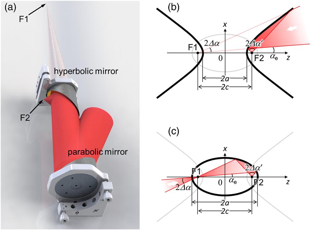
In a strong-field or ultrafast laser physics experiment, a rotational parabolic mirror focuses a collimated laser beam to its focus, where an experimental target is located for light–matter interactions. Figure 1(a) shows that when a rotational hyperbolic mirror is introduced, with one of its foci located at the focus of the rotational parabolic mirror, the reflected beam will be focused at its other focus, where the focusing angular aperture will be enlarged, resulting in a smaller focal spot. Figure 1(b) shows a profile containing the reflection and focusing processes, and a Cartesian coordinate system of -- is set up with reflections in the - plane and two foci on the axis and symmetric about the axis. The input and output angular semi-apertures are and , which are located at the input and output foci and , respectively. The semi-major axis of the hyperbola is , and the eccentricity is , which is larger than 1 for hyperbolas. The angle between the edge of the beam and the axis is defined as the edge angle , which should be larger than zero to avoid the experiment target blocking the input beam. For comparison, Fig. 1(c) shows the secondary focusing using a rotational ellipsoidal mirror, where the two foci of the ellipse have the same locations: and . The semi-major axis of the ellipse is , and the eccentricity is smaller than 1 for ellipses.
Sign up for Advanced Photonics Nexus TOC. Get the latest issue of Advanced Photonics Nexus delivered right to you!Sign up now
Figure 1.(a) Schematic of tight focusing using a parabolic mirror and a hyperbolic mirror. Illustration and comparison of secondary focusing using (b) hyperbolic and (c) ellipsoidal mirrors. and are input and output angular apertures, respectively.
Using the calculation model given in Appendix A, the angular apertures at the two foci are calculated for different cases. Figures 2(a) and 2(b) show the variation of the magnification ratio and the output angular aperture with different eccentricities , respectively. The edge angle is fixed at and the results are given for three input angular apertures of , 20 deg, and 30 deg. The calculations show that, first, the angular aperture can be increased by optimizing the eccentricity ; second, there exists an optimal eccentricity for both ellipses () and hyperbolas (), which corresponds to an optimal magnification ratio and an optimal output angular aperture with the maximum values. It can be found that for the same input (i.e., the same input angular aperture and the same edge angle ), the optimal magnification ratio and the optimal output angular aperture is the same for both ellipses and hyperbolas. Table 1 gives the optimal focusing conditions for both ellipses and hyperbolas, when the edge angle is and the input angular apertures are , 20 deg, and 30 deg. In addition, Fig. 2(a) shows that the magnification ratio increases as the input angular aperture decreases, while Fig. 2(b) shows that the output angular aperture increases as the input angular aperture increases. This indicates first, the need to optimize ellipsoidal and hyperbolic mirrors for the optimal conditions, especially when the input angular aperture is small; second, even with the optimal conditions, a large input angular aperture is preferred for a larger optimal output angular aperture.
Figure 2.Variations of (a) magnification ratio and (b) output angular aperture with eccentricity for different input angular apertures , 20 deg, and 30 deg and a fixed edge angle .
Based on the optimal focusing condition for a input angular aperture and a edge angle, i.e., the optimal output angular aperture and optimal eccentricity for a hyperbola, the focused field of a typical fs-PW laser is numerically simulated. The fs-PW laser is assumed to have a Gaussian spectrum with a 60 nm FWHM bandwidth centered at 800 nm, which corresponds to the current Ti:sapphire fs-PW lasers.20–22 The focusing model by Wolf et al.23 is used in the simulation and given in Appendix B, and therefore the field in the focal region is assumed to come from a cutoff portion of a uniform spherical wave. Another Cartesian coordinate system of is set up at the geometrical focus where the –axis is the beam propagation direction. Figures 3(a) and 3(d) show the intensity distributions of the laser center wavelength of in the focal region for the input and output angular apertures of and , and the spatial coordinates are normalized by the laser center wavelength . The focal spot size (FWHM) is reduced from about 3.12 to , and meanwhile, the focal depth (FWHM) decreases from about 61 to , which agrees well with the results in Fig. 3(b) of Ref. 23. Figures 3(b) and 3(c) show the spatiospectral intensity distribution and spatiotemporal intensity distribution of the pulsed beam in the geometrical focal plane for , and Figs. 3(e) and 3(f) show the results for . During the magnification of angular apertures (from 20 deg to 84.3 deg), the spectral and temporal properties of the pulsed beam at the geometrical focal plane remain unchanged, except for a spatially smaller focal spot. This result shows that secondary focusing using rotational hyperbolic mirrors can reduce the focal spots of current fs-PW lasers to a single-wavelength size. The problem, however, is that the focal depths are also significantly reduced, which makes it challenging to accurately adjust the targets’ positions.
Figure 3.When the angular apertures are (a)–(c) 20 deg and (d)–(f) 84.3 deg, (a) and (d) spatial intensity distribution in the focal region for the laser center wavelength, and (b) and (e) spatiospectral and (c) and (f) spatiotemporal intensity distributions in the geometrical focal plane for a 60 nm FWHM bandwidth Gaussian-pulsed beam. Curves are on-axis profiles.
Realizing the regime or the laser has always been the way forward for the ultra-intense ultrashort lasers. We keep the magnified angular aperture unchanged and broaden the spectral bandwidth to 600 nm (FWHM), with a 12-order super-Gaussian profile and a 600 to 1200 nm FWHM spectral range. Figure 4(a) shows the electric-field distributions of 1200, 900, and 600 nm monochromatic waves in the - focal region, and Fig. 4(b) shows the corresponding intensity distributions. Due to the ultrabroadband bandwidth with one octave, the distribution in the focal region clearly depends on the spectrum, and the spatial profile increases with increasing wavelength. The focal spot sizes (FWHM) of 1200, 900, and 600 nm waves are about 1.05, 0.79, and , respectively, and the corresponding focal depths (FWHM) are about 4.65, 3.50, and , respectively. The focal spot size and the focal depth remain unchanged at about 0.88 and , respectively, although the absolute values are different for different waves. The spatiospectral intensity distribution in the geometrical focal plane , as shown in Fig. 4(c), also clearly illustrates the spectral dependence. After the Fourier transform from spectral frequency to time, the spatiotemporal intensity and electric-field distributions and of the pulsed beam in the geometrical focal plane are shown in Figs. 4(d) and 4(e), which have symmetrical profiles in both space and time. The FWHM spatiotemporal size is about , which meets the definition of the regime or the laser.1,3 The numerical simulation shows that the combination of a rotational parabolic mirror and a rotational hyperbolic mirror provides a way to enhance the current ultra-intense ultrashort lasers to the regime or the laser when the wavefront errors24,25 and the spatiotemporal coupling errors26–30 are removed. In particular, wavefront correction is critical for tight focusing. In the two-step focusing, the planar wavefront enters the first mirror, a parabolic mirror, and then the spherical wavefront enters the second mirror, a hyperbolic or ellipsoidal mirror. In previous experiments using ellipsoidal mirrors,17,18 near-ideal single-wavelength-sized focal spots have been achieved successfully, indicating that the wavefront control can meet the experimental needs.
Figure 4.When the angular aperture is 84.3 deg, spatial (a) electric-field and (b) intensity distributions in the focal region for 1200, 900, and 600 nm wavelengths, and (c) spatiospectral, spatiotemporal (d) intensity and (e) electric-field distributions in the geometrical focal plane for a 600 nm FWHM bandwidth 12-order super-Gaussian pulsed beam. Curves are on-axis profiles.
In this article, a method with hyperbolic mirrors is proposed to magnify the angular aperture of focusing, e.g., from 20 deg to 84.3 deg (the f-number from to ). Since the focal length is still slightly larger than the beam radius, the Debye approximation is valid23 and the result is not sensitive to polarization.31–33 In this case, for simplification, the scalar diffraction theory of a finite spherical wave proposed by Wolf et al.23 is used. In the next-step work, the polarization effect must be considered as the f-number decreases to very small. In addition, the focusing property of parabolic mirrors as boundary conditions for the Stratton–Chu integral34 has been well studied,35,36 since almost all current ultra-intense ultrashort lasers use parabolic mirrors as focusing optics. To apply this method to experiments, another next-step work is to study the Stratton–Chu integral with the boundary condition of the combination of a parabolic mirror and a hyperbolic mirror.
Since the optimal output angular aperture is the same for hyperbolic and ellipsoidal secondary focusing mirrors (see Fig. 2) and the ideal focusing of a cutoff portion of a uniform spherical wave is considered, the secondary focusing results are the same for both methods using hyperbolic and ellipsoidal secondary focusing mirrors. However, when the optimal output angular aperture is increased to much larger than 90 deg, the above two approximations do not hold, and differences would appear, requiring further in-depth study.
Due to the short working distance of the hyperbolic secondary focusing mirror, which is approximately equal to half of the semi-major axis, mirror contamination and protection should be considered in the design and engineering.
When the two-step focusing method using an ellipsoidal secondary focusing mirror was first proposed, a plasma mirror, i.e., an ellipsoidal plasma mirror, was considered for strong-field experiments because the second mirror, an ellipsoidal mirror, is much smaller than the first mirror, a parabolic mirror.17,18 Here, although the hyperbolic mirror is much larger than the ellipsoidal mirror, the problem of damage still needs to be considered, and even a hyperbolic plasma mirror needs to be used as well.
In this article, since the optimal output angular aperture is not larger than 90 deg, Refs. [31] and [32] show that the optical field is centrosymmetric in the - plane, and the distribution along the axis is not shown. However, when it is increased to much larger than 90 deg, the three-dimensional spatiotemporal optical field needs to be studied in the focal region.
In conclusion, we have proposed that hyperbolic mirrors (another important conic section that also has two foci) can also be used as secondary focusing mirrors after parabolic mirrors to reduce the focal spot size to a single wavelength. Similar to the method using ellipsoidal mirrors, the input large focal spot is located at one focus, while the output small focal spot is located at the other focus. The difference, however, is that with an ellipsoidal mirror, the input focal spot is a real image, while with a hyperbolic mirror, the input focal spot is a virtual image, which avoids some unwanted strong-field effects in a nonideal vacuum. The optimal focusing condition of this method is presented, and the enhanced tight focusing in a typical fs-PW laser and the laser are numerically simulated. This work provides the possibility of achieving single-wavelength-sized focusing for ultra-intense ultrashort lasers, which in turn provides the possibility of realizing the regime or the laser in the future.
4 Appendix A: Calculation of Angular Aperture Magnification
Because an arbitrary optical ray towards the focus is reflected by the hyperbola to the focus [see Fig. 1(b)] and an arbitrary optical ray from the focus is reflected by the ellipse to the focus [see Fig. 1(c)], the equations of the two optical rays before and after the reflection are given by where and are angles of the incident and reflected optical rays relative to the axis. Since the two optical rays intersect at the reflection point , from Eq. (1) we have the relationship between two angles and ,
The hyperbola and ellipse are, respectively, described as and where and are semi-major and semi-minor axes, respectively. Because the reflection point is on the hyperbola or ellipse, by substitution of the first equation in Eq. (1) with Eq. (3) or Eq. (4), the horizontal coordinate of the reflection point is given as which is the same for both an ellipse and a hyperbola.
By substitution of Eq. (5) with Eq. (2), the angle of the reflected optical ray becomes a function of the angle of the incident optical ray, which is also influenced by the parameters and , i.e., the eccentricity , of a hyperbola or ellipse. For a beam focused to the focus with an input angular aperture and an edge angle , as shown in Fig. 1, the output angular aperture at the focus can be calculated by , and the magnification ratio is given by .
5 Appendix B: Simulation of Field Distribution in the Focal Region
Based on the work of Wolf et al.,23 when a monochromatic, homogeneous, converging spherical wave diffracts at a circular aperture with a radius close to the focal length, the electric-field distribution in the focal region can be described as where is the wavenumber, is a constant amplitude, is the angular semi-aperture, is the propagation axis perpendicular to the circular aperture, is the vertical axis, and is the first-kind and zero-order Bessel function.
Zhaoyang Li is a professor at Zhangjiang Laboratory, Shanghai, China, with interests in ultra-intense laser technology and engineering. He received his bachelor’s, master’s, and doctoral degrees from Beijing Institute of Technology, China Academy of Engineering Physics, and Nanjing University of Science and Technology, respectively. He was an assistant professor at Institute of Laser Engineering Osaka University; at Shanghai Institute of Optics and Fine Mechanics, Chinese Academy of Sciences; and at Shanghai Institute of Laser Plasma.
Yanqi Liu is an associate professor at Zhangjiang Laboratory, Shanghai, China, with interests in ultra-intense laser technology and engineering. He received his bachelor’s and master’s degrees from Changchun University of Science and Technology in 2007 and 2011, respectively. He was a research assistant, research associate, and associate professor at Shanghai Institute of Optics and Fine Mechanics, Chinese Academy of Sciences from 2011 to 2022.
Xiaoyang Guo is an associate professor at Shenzhen Technology University, Guangdong, China, with interests in femtosecond laser technology and engineering. He received his bachelor’s and doctoral degrees from Central South University and Shanghai Institute of Optics and Fine Mechanics in 2010 and 2015, respectively. He was a postdoc in Kyoto University and Osaka University from 2015 to 2018.
Yuxin Leng is a professor at Shanghai Institute of Optics and Fine Mechanics (SIOM), Chinese Academy of Sciences (CAS), Shanghai, China, with interests in ultra-intense lasers and physics. He received his bachelor’s and doctoral degrees from Wuhan University and SIOM, CAS in 1997 and 2002, respectively. He is an assistant/associate/full professor at SIOM, CAS; director of State Key Laboratory of High Field Laser Physics, SIOM, CAS; and vice-director of SIOM, CAS.
Ruxin Li is a professor at SIOM, CAS, Shanghai, China, with interests in ultra-intense lasers and physics. He received his bachelor’s and doctoral degrees from Tianjin University and SIOM, CAS, in 1990 and 1995, respectively. He was elected as a fellow of Optica (formerly OSA) in 2014, Academician of CAS in 2017, and Academician of Third World Academy of Sciences in 2021.
 AI Video Guide
  AI Picture Guide
 AI One Sentence