Abstract
The ultimate capacity of a cladding-pumped 10/130 Tm:fiber is experimentally investigated with a 793 nm laser diode bidirectionally pumped amplifier. The laser system works stably at the output powers of 52 W, 65 W, and 87 W. Eventually, the damage of the amplifier occurs when the output power reaches about 103.5 W with a total incident pump power of 176.8 W. Considering the incident seed power of 12.3 W, the amplifier conversion efficiency is estimated to be about 51.6% before it is damaged. With valuable exploration, we achieve the first air-cooling 60 W Tm:fiber laser at 1945.845 nm with a spectral linewidth of 0.4 nm. The laser power stability reaches 1.24% during a continuous test time of >65 h. The beam quality is measured as and .Continuous-wave (CW) 2 μm lasers are attractive for industrial transparent plastics processing, medical treatment, and military applications[1–5]. Compared to the all-solid-state scheme, combining the double-cladding Tm:fiber with the diode cladding pumping technique is more popular for CW lasers. The great advantages of the all-fiber scheme are near diffraction-limited beam quality, better thermal management, and high compatibility for the flexible applications. With a water chiller, laser power of hundreds of watts, even more than 1 kW, has been achieved successively with large mode fiber[6–10]. The core diameters were all , and the beam qualities were not good enough. In our previous work[11], we demonstrated a 227 W 1907.8 nm laser with a single 25/400 Tm:fiber oscillator, and the beam quality reached . A Tm:fiber with core diameter of is mostly used in the lower power situation. The current reported highest output power is with the Nufern 10/130 large mode area (LMA) Tm:fiber[12]. In 2013, the maximum output power reached 170 W at 1064 nm in the work of Zhang et al.[13] with a 10/125 polarization maintaining (PM) Yb:fiber and was boosted up to 300 W in 2017[14]. With the 10/130 LMA Yb:fiber, the maximum output power reached 200 W at 1018 nm by Ottenhues et al. in 2015[15] and was boosted up to 300 W in 2019 by Tian et al.[16]. Considering the conversion efficiency and output in the 25/400 Tm:fiber amplifier[10], the output capacity of the 10/130 Tm:fiber laser (TFL) system should be if only it can bear the thermal loading, which is worthy of experimental testing. Moreover, the 10/130 fiber with 250 μm coating is easily spliced and coiled, which should be essential for the production and cost reduction of the TFL.
In this Letter, the ultimate output capacity of the 10/130 LMA TFL is studied experimentally, which should be worthwhile for the final product design of the 100 W transverse electromagnetic () TFL. This work preliminarily proved that the current damage threshold is around 103 W with a rectangular gain-fiber-cooling groove and thermally conductive silicone grease. The long-term data proves it can work safely around 90 W with the water-cooling scheme. A compact 60 W air-cooling TFL is also achieved with near diffraction-limited beam quality.
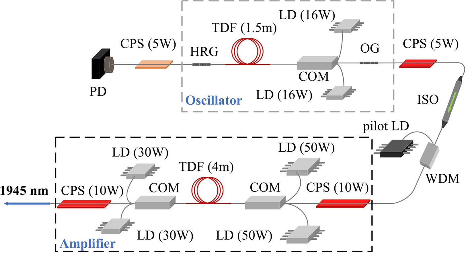
Figure 1 shows the experimental setup of the 10/130 TFL system. It is a common master oscillator fiber amplifier (MOFA), which contains a single backward-pumped fiber oscillator seed and a bidirectionally pumped fiber amplifier. The gain fibers are the newly improved single-mode 10/130 Tm:fiber (Nufern SM-TDF-10P/130-M), which absorbs the 793 nm pump light with efficiency of 3.6 dB/m. The air-cooling oscillator seed contains a pair of homemade uniform fiber Bragg gratings (HRG, high reflection grating, , ; OG, output grating, , ), and two 16 W 793 nm pump diodes. The maximum output seed power exceeds 12 W after the isolator (ISO). The amplifier contains a pair of 50 W laser diodes (LDs) as the forward pump source and a pair of 30 W LDs as the backward pump source. The length of the Tm:fiber is 4 m for the amplifier, which corresponds to total pump absorption of about 96.37%. Two 10 W, cladding power strippers (CPSs) are included to eliminate the residual pump power and escaped signal power. To explore the ultimate capacity of the 10/130 Tm:fiber, the gain fiber is coiled on a copper heat sink with a water-cooling temperature of . The groove shape of the copper heat sink is rectangular with a cross section of . High thermal conductivity, , silicone grease is adopted to package the Tm:fiber. A single-mode fiber-coupled 658 nm diode laser is combined into the amplifier with a wavelength division multiplexer (WDM) to determine whether it is possible to act as the pilot light in the fiber core.
Sign up for Chinese Optics Letters TOC. Get the latest issue of Chinese Optics Letters delivered right to you!Sign up now

Figure 1.Layout of 10/130 TFL system (PD, photo diode; CPS, cladding power stripper; HRG, high reflection grating; TDF, -doped fiber; COM, combiner; LD, laser diode; OG, output grating; ISO, isolator; WDM, wavelength division multiplexer).
The laser power measurement was finished with a 300 W power meter (L300W-LP1-50, Ophir Optronics). The laser wavelength was measured with a high-resolution spectral meter (MS3504i, SOL). The beam quality was evaluated with an infrared beam analyzing device (M2MS-BP209IR2/M, Thorlabs).
In the amplifier experiment, three divided stages were arranged to explore the maximum output. The output power curve is shown in Fig. 2. During Stage I, the 12.3 W seed laser was injected and only forward pump LDs worked. The maximum forward pump power was about 95.6 W. We obtained about 64 W amplified laser power. During Stage II, a forward pump power of 95.6 W kept being injected, and backward pump LDs started working. The maximum backward pump power was 66.86 W. Then, the amplified laser power boosted up to about 99.6 W. After affirming the long-term safety operation, the forward pump LDs increased again, namely Stage III. Finally, when the total pump power reached 176.53 W, the amplifier reached the output limit of 103.51 W. Apart from the injected seed power of 12.3 W, the optical-optical conversion efficiency of the amplifier reached 51.6%. In Fig. 2, the red dot with the red line denotes the experimental results, and the black dot with the black line denotes the simulation results based on our previous TFL models in Refs. [17–19], which, in this work, only take the linearly polarized () mode into consideration. The experimental results are merely a little lower than the simulation results when the forward pump power is lower than 40 W during Stage I. Then, the theoretical results get lower and lower. The maximum difference was about 8.4% before the Tm:fiber was damaged. The experimental slope efficiency is fitted as 55%, which is higher than the theoretical value of 47%. The simulated laser power distribution along the gain fiber is shown in Fig. 3(a) with the full capacity. But, it only worked stably for several minutes before the damage of the gain fiber occurred. The seed laser was not turned off in time, and the fiber fuse appeared, which is depicted as the subgraph in Fig. 2.
Figure 2.Experimental and theoretical output curves of 10/130 Tm:fiber amplifier. (A 4.5 wt.% concentration is adopted in the theoretical simulation, which is credible from Coherent-Nufern.)
Figure 3.(a) Simulated laser power distribution, (b) three-dimensional and (c) longitudinal temperature distributions along the length direction of the amplifier Tm:fiber. [The heat transfer coefficient at the boundary between fiber coating and the water-cooling copper sink was set as .]
The thermal conducting restrictions are figured as the most important issues for damaging the Tm:fiber. With a similar analysis in our previous work[20], the numerical thermal simulation was easily achieved. In the situation of above full capacity, the maximum temperature of the fiber cladding reaches , as shown in Figs. 3(b) and 3(c). The ideal polymer coating will be damaged when the temperature is approaching [6]. But actually, the polymer coating of commercial double-clad fibers is sensitive to higher thermal load. It is better to control the temperature of the coating <60°C for long-term operation. Even then, the damage occurred too quickly every time, which made us believe that the damage may not be thermally initiated, and other mechanisms exist, such as fiber thermal lens and self-oscillation. In the current bidirectionally pumped amplifier, the temperature difference between the first main splicing point and the second one is huge, nearly , as shown in Fig. 3(c), which indicates that the backward pump power of the amplifier can be further increased to optimize the thermal distribution and output characteristics.
Before the amplifier was damaged, the stabilities of output power at three different output powers (52 W, 65 W, and 87 W) were measured in several hours, which are shown in Fig. 4. The estimated power stabilities at 52 W, 65 W, and 87 W are 0.75% (240 min), 0.38% (240 min), and 0.45% (480 min), respectively. Here, we adopt the ratio of sample standard deviation and average value to estimate the output stability.
Figure 4.Laser stability measurements of output power at (a) 52 W, (b) 65 W, and (c) 87 W.
A pilot light is usually necessary for actual applications. First, a low power of 3 mW 658 nm LD was inserted between the seed and amplifier stage, as shown in Fig. 1. But the pilot light was too weak at the output end no matter whether the 1945 nm laser worked or not. Then, a high power of 60 mW 658 nm LD was adopted to check it again. There was still no obvious enhancement. Meanwhile, we observed obvious blue light at the output end. With a visible spectrometer (AvaSpec-ULS4096CL-EVO, Avantes), the central wavelength was measured around 457.15 nm, which is shown in Fig. 5(a). To explain this phenomenon, a detailed energy level structure is included in Fig. 5(b)[21]. The absorption transition, , just corresponds to the 658 nm light. The emission transition, , just corresponds to the 457 nm light. Thus, the above measured 457 nm blue light is due to the up-conversion effect of the Tm:fiber. Although the up conversion of 658 nm can be met at both and transitions, the latter transition process is more possible for the much shorter lifetime of (0.7 ms) than ()[21]. Anyway, it is impossible to couple the 658 nm pilot light with the high-power signal laser in the same -doped fiber core unless you adopt a high-power WDM after the amplifier.
Figure 5.(a) Blue light emission spectrum with the 658 nm LD exciting; (b) a detailed energy structure of a silica Tm:fiber.
Based on the above experimental and theoretical exploration, a compact 60 W air-cooling TFL was finished with only one 16 W backward 793 nm LD for the oscillator seed and two backward 50 W 793 nm LDs for the amplifier stage. The red pilot light was coupled into the cladding with a pump combiner after the amplifier.
The maximum output power is 62 W with a total electrical power consumption of 615 W, which indicates the laser plug-off efficiency is . At the maximum output case, the laser spectra, beam quality, and power stability are measured. The laser central wavelength is measured as 1945.845 nm with a spectral linewidth of 0.398 nm, which is shown in Fig. 6(a). Figure 6(b) shows the near diffraction-limited beam quality, and . The laser power stability reaches 1.24% during a continuous test time of 68 h, which is shown in Fig. 6(c). This air-cooling laser has been successfully applied in the transparent plastics welding equipment and stably operated for more than 3000 h. The 1945 nm laser is especially useful for the micro-welding of medical microfluidic devices with a high-speed scanner[22].
Figure 6.(a) Typical laser spectrum, (b) beam quality measurement, and (c) laser stability measurement at the maximum output of air-cooling TFL.
In summary, we have explored the ultimate capacity of the 10/130 TFL in the water-cooling amplifier system. The gain fiber was destroyed when the output power reached 103.5 W. The long-term operation indicated the feasibility of a 90 W level 10/130 TFL with the water-cooling method and a 60 W level 10/130 TFL with the air-cooling method. It is also hopeful to further boost the laser power to 120 W with a series of optimizations, such as increasing the seed power to and adopting V-shape grooves for the gain fiber for better thermal management.
References
[1] Y. Ren, Z. Qin, G. Xie, Z. Qiao, T. Hai, P. Yuan, L. Hu. Chin. Opt. Lett., 16, 020020(2018).
[2] E. C. Ji, Y. Yao, Y. J. Huang, S. Lu, Q. T. Lue. Proc. SPIE, 10964, 109643S(2018).
[3] K. Scholle, M. Schäfer, S. Lamrini, M. Wysmolek, M. Steinke, J. Neumann, P. Fuhrberg. Proc. SPIE, 10512, 105120O(2018).
[4] C. Yang, Y. Ju, B. Yao, Z. Zhang, T. Dai, X. Duan. Chin. Opt. Lett., 14, 061403(2016).
[5] T. Sumiyoshi, H. Sekita, T. Arai, S. Sato, M. Ishihara, M. Kikuchi. IEEE J. Sel. Top. Quantum Electron., 5, 936(1999).
[6] Y. Fan, B. He, J. Zhou, J. Zheng, H. Liu, Y. Wei, J. Dong, Q. Lou. Opt. Express, 19, 15162(2011).
[7] R. Tumminelli, V. Petit, A. Carter, A. Hemming, N. Simakov, J. Haub. Proc. SPIE, 10512,, 105120M(2018).
[8] M. Meleshkevich, N. Platonov, D. Gapontsev, A. Drozhzhin, V. Sergeev, V. Gapontsev. European Conference on Lasers and Electro-Optics and the International Quantum Electronics Conference, CP2_3(2007).
[9] T. Walbaum, M. Heinzig, T. Schreiber, R. Eberhardt, A. Tünnermann. Opt. Lett., 41, 2632(2016).
[10] T. Ehrenreich, R. Leveille, I. Majid, K. Tankala, G. Rines, P. Moulton. Proc. SPIE, 7580, 758016(2010).
[11] Z. Y. Hu, P. Yan, Q. R. Xiao, Q. Liu, M. L. Gong. Chin. Phys. B, 23, 104206(2014).
[12] A. Carter, B. Samson, J. Ding, G. Frith, K. Tankala. Proc. SPIE, 7914, 79140J(2011).
[13] L. Zhang, S. Cui, C. Liu, J. Zhou, Y. Feng. Opt. Express, 21, 5456(2013).
[14] X. Zhao, Y. Yang, H. Shen, X. Chen, G. Bai, J. Zhang, J. Zhou. High Power Laser Sci. Eng., 5(2017).
[15] C. Ottenhues, T. Theeg, K. Hausmann, M. Wysmolek, H. Sayinc, J. Neumann, D. Kracht. Opt. Lett., 40, 4851(2015).
[16] J. Tian, Q. Xiao, D. Li, Y. Huang, Z. Wang, P. Yan, M. Gong. OSA Continuum, 2, 1138(2019).
[17] Z. Hu, P. Yan, Q. Liu, E. Ji, M. Gong. J. Opt. Soc. Am. B, 31, 3181(2014).
[18] Z. Hu, P. Yan, Q. Liu, E. Ji, Q. R. Xiao, M. Gong. Appl. Phys. B, 118, 101(2015).
[19] E. Ji, Q. Liu, Z. Hu, M. Gong. Chin. Phys. B, 24, 104210(2015).
[20] E. Ji, Y. Shen, M. Nie, X. Fu, Q. Liu. Appl. Phys. B, 123, 129(2017).
[21] B. M. Walsh, P. B. Norman. Appl. Phys. B, 78, 325(2004).
[22] J. De Pelsmaeker, G. J. Graulus, S. Van Vlierberghe, H. Thienpont, D. Van Hemelrijck, P. Dubruel, H. Ottevaere. J. Mater. Process. Technol., 255, 808(2018).