Author Affiliations
1Department of Engineering Physics, Tsinghua University, Beijing 100084, China2Institute of Modern Physics, Chinese Academy of Sciences, Lanzhou 730000, China3Xi’an Jiaotong University, Xi’an 710049, China4Institute of Applied Electronics, CAEP, Mianyang 621900, Chinashow less
Abstract
High-energy electron radiography (HEER) is a promising diagnostic tool for high-energy-density physics, as an alternative to tools such as X/γ-ray shadowgraphy and high-energy proton radiography. Impressive progress has been made in the development and application of HEER in the past few years, and its potential for high-resolution imaging of static opaque objects has been proved. In this study, by taking advantage of the short pulse duration and tunable time structure of high-energy electron probes, time-resolved imaging measurements of high-energy-density gold irradiated by ultrashort intense laser pulses are performed. Phenomena at different time scales from picoseconds to microseconds are observed, thus proving the feasibility of this technique for imaging of static and dynamic objects.I. INTRODUCTION
High-energy-density physics (HEDP) is the study of matter under extreme conditions, often defined as >1 Mbar (100 GPa) pressure or >100 GJ/m3 energy density,1 such as those occurring in heavy-ion-driven fusion,2 laser-driven fusion,3 and similar processes. Under these conditions, the hydrodynamic response of the matter is a high expansion velocity in the range of micrometers per nanosecond (μm/ns), thus posing various challenges to diagnostic techniques, such as the need for high spatiotemporal resolution, high areal-density resolution, and a large dynamic range.4 Charged-particle radiography5 has been developed as a diagnostic tool for many years by the Los Alamos National Laboratory6–8 and other institutions.9–11 As an alternative to the familiar proton radiography, high-energy electron radiography (HEER)12 has attracted considerable interest owing to its potential to provide high spatiotemporal resolution with much greater accessibility and ease of manipulation. Recent work has improved the spatial resolution of HEER to a few micrometers,13,14 and this technique has been used to image dynamic processes.14 However, full advantage has yet to be taken of high-energy electron probes with their short pulse duration and flexibly tunable time structure, and this is especially the case with high-brightness electron probes generated from state-of-the-art RF photo-injectors. In a common photo-injector, the pulse duration of an electron bunch can be as low as the picosecond or even femtosecond scale, and synchronization between the RF and laser can be controlled to the sub-picosecond scale. Therefore, the accuracy of time-resolved imaging of dynamic process in a pump–probe scheme can reach the picosecond scale, at which a number of ultrafast phenomena can be observed.
In this paper, we demonstrate the use of high-brightness electron probes and a compact imaging lens composed of high-gradient permanent magnet quadrupoles (PMQs) to capture the entire dynamic process of laser ablation of gold mesh over a long time scale, with spatiotemporal resolution on the scales of tens of picoseconds and micrometers. Successful implementation of dynamic HEER in a pump–probe scheme using an ultra-fast intense laser pump and a picosecond-long high-energy electron probe reveals its potential for direct visualization of fast dynamic phenomena in high-energy-density matter.
II. DYNAMIC HEER EXPERIMENT
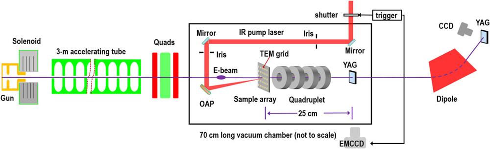
A. Experimental setup
Proof-of-principle experiments on dynamic HEER were carried out at the Tsinghua Thompson scattering X-ray source platform,15 which consists of a high-gradient normally conducting RF gun working at 2.856 GHz, a 3 m long traveling-wave accelerating tube, and some other elements for beam control and diagnosis. The schematic layout of this experiment is shown in Fig. 1. High-brightness electron probes with 300 pC bunch charge, 1 mm mrad normalized emittance, 10 ps pulse duration, 45 MeV kinetic energy, and 0.1% energy spread are generated from the photo-injector. At the exit of the accelerator, a triplet of electromagnetic quadrupoles is used to focus the beam and match it to the imaging lenses section, which is installed entirely within the vacuum chamber. Electrons passing through the sample travel through a PMQ-based Russian quadruplet (RQ) and finally form a point-to-point image of the sample on a high-resolution YAG screen. The image is recorded by a lens-coupled CCD outside the chamber. A dipole magnet at the end of the beamline is used to calibrate the kinetic energy as well as to measure the energy spread of the electron probe.

Figure 1.Schematic of the dynamic HEER experimental layout. High-brightness electron probes passing through the sample form a point-to-point magnified image of the sample with the magnetic imaging system. To image the irreversible laser ablation process, a specially designed sample holder containing numerous identical grids is mounted on a two-dimensional translation stage in the xy plane.
The RQ imaging lens is composed of two pairs of PMQs, which have found wide use in high-energy particle transport,16 focusing,17 and imaging,18,19 owing to their one to two order of magnitude higher gradients than common electromagnetic quadrupoles. Since their gradients cannot be tuned, the positions of these PMQs are optimized by the COSY INFINITY code.20 The parameters of the optimized layout of the RQ are listed in Table I. The fitness of the imaging section is verified by particle tracking simulation using the ASTRA code,21 with both a hard-edge PMQ model (the same model as used in the COSY INFINITY code) and measured PMQ field distribution. In Fig. 2, a point-to-point image of a 100% initial contrast sample (i.e., a standard 200-mesh hexagonal TEM grid) is formed, with a magnification factor of about 1.1. The simulated imaging process shows a good match with the experimental outcomes. The resolution of this imaging system is determined to be 15 µm by measuring the edge spread function of a bar of the grid, as shown in Fig. 3.
| Parameter | Length (mm) | Gradient (T/m) | Position (m) |
|---|
| A1 | 18.63 | −186.1 | 0.029 29 |
| B1 | 20.04 | 214.2 | 0.083 66 |
| B2 | 20.16 | −209.0 | 0.139 15 |
| A2 | 18.63 | 186.3 | 0.193 48 |
Table 1. Parameters of the Russian quadruplet.
Figure 2.(a) Simulated beam transverse envelope in the imaging section. (b) Simulated static image of a 200-mesh hexagonal TEM grid. (c) Experimental static image of a 200-mesh hexagonal TEM grid.
Figure 3.(a) Image of the central part of a 200-mesh square TEM grid. (b) Beam intensity distribution in the x plane, i.e., the edge spread function (ESF) of the grid bar in the region of interest marked by the red box in (a). (c) The line spread function (i.e., the derivative of the ESF) of the grid bar and its Gaussian fit plot. The 1σ resolution is determined to be about 15 µm.
B. Calibration of time-of-zero
In a pump–probe scheme, the first step in imaging dynamic processes is to calibrate the time-of-zero, i.e., the beginning timestamp of the laser-initiated excitation of the sample. Electron deflectometry or shadowgraphy22,23 is a widely used technique for determining the time-of-zero in laser-pump–electron-probe experiments, where electrons are deflected by transient electromagnetic fields induced by high-power-density laser illumination of a metal target. In addition, this technique has been found to be a promising tool for the diagnosis of transient electric and magnetic fields24 and high-density rapidly evolving plasmas.25 However, the energy of electron probes used in previous experiments has been limited to tens of keV up to a few MeV, since highly energetic electrons are more difficult to deflect. The advantage of higher-energy electrons is obvious in that they can penetrate denser plasmas and detect higher electric and magnetic fields.24
In this experiment, an ultra-short high-power intensity pump laser of 28 (±5%) mJ pulse energy and 40 ± 2 fs pulse duration (full width at half height) illuminates a small area (<30 µm) of the gold mesh, and thus the power density is about 5 × 10¹⁶ W/cm2. With the RQ moved off the z axis, shadowgraphs of the laser-irradiated sample are obtained. At a certain delay time, for example, T = 4.8 ns in Fig. 4(a), the beam intensity of the illuminated area falls, while the intensity in the outer part increases owing to the deflection effect, with the formation of a “valley–peak” intensity distribution pattern, which is very similar to what was observed in previous experiments.24 Moreover, by measuring the position offsets of the centroids of each beamlet passing through the mesh holes with the pump laser on, one can calculate the deflection angle of the electrons located in the “peak” area, which has a maximum value of about 1.7 mrad. By tuning the time delay between the electron probe and the pump laser, the persistence time of this phenomenon is determined to be approximately 8 ns.
Figure 4.(a) Electron deflection by transient electromagnetic fields at T = 4.8 ns. (b) Zoomed view of the areas illuminated by the laser.
C. Imaging the melting process
With the time-of-zero known, the imaging mode was shifted from shadowgraph to radiograph, with the RQ moved back to the beam axis. Since the photo-injector works in a single-pulse mode with a repetition rate of 10 Hz, the whole of the unrepeatable melting process cannot be recorded with a single pulse. Therefore, we designed a special sample holder containing numerous identical gold meshes, and, by carefully varying the time delay over a large dynamic scale, we could acquire a sequence of images of the sample at different times to piece together an entire movie of the melting process, as shown in Fig. 5.
Figure 5.Typical images of the gold mesh during the melting process. The black squares in these images indicate the illuminating area.
By analyzing the evolution of the beam intensity as well as the surface profile of the sample, the whole melting process can be divided into three different phases. In the first phase, lasting from the beginning to about 10 ns, radiographs of the phase are almost the same as the background shots, unlike the obvious deflection observed in the shadowgraph mode. This can be explained by the fact that the relatively small scattering angles imprinted on electrons by the gold mesh could not be effectively turned into image contrast in this point-to-point imaging mode. The second phase, lasting from 10 ns to about 1.2 µs, is characterized by a decrease in intensity while the surface profile of the sample remains almost unchanged, as shown in Fig. 6. With the help of scanning electron microscopy, surface splits along the joints between adjacent patches on the back of the grid can be observed, indicating that there are neutral-particle ejecta in the ablation process.26 In the final phase, from 1.2 µs to 5 µs, the intensity in the melted area gradually increases. In this phase, the area with intensity higher than that in the surrounding mesh holes is considered to be melted. The size of the area in the pump-shot radiograph is compared with that in the after-shot radiograph at each time delay to give the melting ratio Apump shot/Aafter shot. The variation of the melting ratio with time is illustrated in Fig. 6(b), where it can be seen that the ratio increases almost linearly until it approaches 1.
Figure 6.Measured intensity of illuminated area (a) and melting ratio (b) at different time delays.
III. SUMMARY
Dynamic HEER of laser-induced metal melting has been demonstrated, with a combination of photo-injector-generated high-brightness electrons and a compact PMQ-based imaging lens. With spatiotemporal resolution on the scales of tens of picoseconds and micrometers, dynamic HEER has proved to be suitable for the study of high-energy-density matter and relevant fast dynamic processes. Moreover, the spatial resolution of this dynamic HEER system could be further improved to the micrometer scale by using an imaging system with a greater magnification factor, thereby allowing more details of these dynamic processes to be observed.
References
[1] R. P. Drake. High-Energy-Density Physics: Fundamentals, Inertial Fusion, and Experimental Astrophysics(2006).
[2] I. Hofmann. Review of accelerator driven heavy ion nuclear fusion. Matter Radiat. Extremes, 3, 1-11(2018).
[3] J. Marozas, A. Maximov, T. Collins, A. Shvydky, F. Marshall, M. Hohenberger, R. McCrory, B. Van Wonterghem, S. Regan, P. Michel, D. Froula, A. Schmitt, J. Myatt, J. Weaver, I. Igumenshchev, S. Ross, V. Goncharov, M. Karasik, J. Knauer, C. Goyon, L. Masse, W. Seka, J. Oh, D. Turnbull, T. Chapman, T. Sangster, R. Betti, A. Solodov, E. Campbell, K. Obenschain, S. Obenschain, S. Reyes, J. Bates, A. Sefkow, M. Rosenberg, P. Radha. Laser-direct-drive program: Promise, challenge, and path forward. Matter Radiat. Extremes, 2, 37-54(2017).
[4] C. Jing, J. Qiu, W. Gai. Electron imaging system for ultrafast diagnostics of hedlp. Target Diagnostics Physics and Engineering for Inertial Confinement Fusion III, 921104(2014).
[5] C. L. Morris, F. Mariam, N. King, F. Merrill, K. Kwiatkowski, A. Saunders. Charged particle radiography. Rep. Prog. Phys., 76, 046301(2013).
[6] P. Goldstone, J. W. Hopson, C. Morris. Proton radiography. Los Alamos Sci., 30, 32(2006).
[7] E. Ables, D. Clark, K. Alrick, C. Morris, M. Aufderheide, D. Clark, P. Barnes, C. Espinoza, K. Buescher, D. Cagliostro et al. Flash radiography with 24 GeV/c protons. J. Appl. Phys., 109, 104905(2011).
[8] K. Alrick, E. Ables, J. Eddleman, S. Cushing, J. Amann, K. Adams, P. Barnes, N. King, M. Crow, S. Balzar et al. An 800-MeV proton radiography facility for dynamic experiments. Nucl. Instrum. Methods Phys. Res., Sect. A, 424, 84-91(1999).
[9] V. Turtikov, A. Kantsyrev, A. Utkin, G. Smirnov, B. Sharkov, S. Kolesnikov, S. Dudin, A. Golubev, V. Demidov, V. Mintsev et al. Application of charged particle beams of TWAC-ITEP accelerator for diagnostics of high dynamic pressure processes. High Pressure Res., 30, 83-87(2010).
[10] A. Vasilevskii, Y. M. Antipov, V. Demyanchuk, N. Ignashin, A. Larionov, Y. G. Karshev, O. Zyat’kov, A. Afonin, I. Gusev, A. Maksimov et al. A radiographic facility for the 70-GeV proton accelerator of the institute for high energy physics. Instrum. Exp. Tech., 53, 319-326(2010).
[11] H. Collaboration, V. Turtikov, A. Golubev, D. Varentsov, F. Merrill, F. Mariam. Proton microscopy at fair. AIP Conf. Proc., 1195, 667-670(2009).
[12] K. Morley, C. Morris, F. Mariam, F. Merrill, A. Hunt, F. Harmon, C. Schwartz, A. Saunders. Electron radiography. Nucl. Instrum. Methods Phys. Res., Sect. B, 261, 382-386(2007).
[13] W. Huang, Z. Chi, M. Liu, Z. Zhou, H. Chen, X. Su, Y. Du, R. Cheng, S. Cao, Z. Zhang et al. Experiments on bright-field and dark-field high-energy electron imaging with thick target material. Phys. Rev. Accel. Beams, 21, 074701(2018).
[14] C. Morris, F. Merrill, F. Mariam, J. Gibbs, S. Imhoff, R. Simpson, L. Neukirch, D. Poulson, J. Goett, J. Perry et al. Demonstration of transmission high energy electron microscopy. Appl. Phys. Lett., 112, 144103(2018).
[15] Z. Zhang, Q. Du, J. Hua, W. Huang, C. Tang, H. Chen, Y. Du, H. Qian, L. Yan, R. Li. Generation of first hard X-ray pulse at Tsinghua Thomson scattering X-ray source. Rev. Sci. Instrum., 84, 053301(2013).
[16] S. Gaillard, M. Schollmeier, M. Geißel, M. Kimmel, S. Becker, A. Blažević, D. Gautier, K. Flippo, K. Harres, F. Grüner et al. Controlled transport and focusing of laser-accelerated protons with miniature magnetic devices. Phys. Rev. Lett., 101, 055004(2008).
[17] A. Tremaine, G. Travish, C. Robbins, P. Frigola, J. Jacob, J. Lim, W. Brown, J. Rosenzweig, S. Anderson. Adjustable, short focal length permanent-magnet quadrupole based electron beam final focus system. Phys. Rev. Spec. Top.-Accel. Beams, 8, 072401(2005).
[18] P. Musumeci, R. Li. Single-shot MeV transmission electron microscopy with picosecond temporal resolution. Phys. Rev. Appl., 2, 024003(2014).
[19] D. Alesini, J. Harrison, P. Frigola, H. To, R. Li, Y. Sun, F. O’Shea, P. Musumeci, J. Maxson, D. Cesar. Demonstration of single-shot picosecond time-resolved MeV electron imaging using a compact permanent magnet quadrupole based lens. Phys. Rev. Lett., 117, 024801(2016).
[20] M. Berz, K. Makino. Cosy infinity version 9. Nucl. Instrum. Methods Phys. Res., Sect. A, 558, 346-350(2006).
[21] K. Flöttmann(2013).
[22] P. Musumeci, H. To, C. Scoby, E. Threlkeld, R. Li. Single-shot 35 fs temporal resolution electron shadowgraphy. Appl. Phys. Lett., 102, 023506(2013).
[23] F. Fei-Chao, Z. Jie, X. Dao, C. Jian-Ming, Z. Peng-Fei, L. Sheng-Guang. Time-resolved visualization of laser-induced heating of gold with MeV ultrafast electron diffraction. Chin. Phys. Lett., 31, 116101(2014).
[24] J. Zhang, J. Cao, F. Liu, P. Zhu, R. Li, Z. Sheng, J. Chen, L. Chen. Mapping transient electric fields with picosecond electron bunches. Proc. Natl. Acad. Sci. U. S. A., 112, 14479-14483(2015).
[25] J. Li, D. Qian, L. Chen, J. Zheng, P. Zhu, R. Li, W. Wang, J. Cao, Z. Zhang, X. Wang et al. Four-dimensional imaging of the initial stage of fast evolving plasmas. Appl. Phys. Lett., 97, 211501(2010).
[26] J. Yang, X. Wang, M. Wang, N. Zhang, X. Zhu. Time-resolved shadowgraphs of material ejection in intense femtosecond laser ablation of aluminum. Phys. Rev. Lett., 99, 167602(2007).