Zongfu Hu, Zhiguo Jiang, Jinfang Wang, Su Mei. Resonator fiber optic gyros with light time-division input and multiplexing output in clockwise and counterclockwise directions[J]. Chinese Optics Letters, 2020, 18(3): 030601
Copy Citation Text
A resonator fiber optic gyro with the light time-division input and multiplexing output (TDM-RFOG) in the clockwise (CW) and counterclockwise (CCW) directions is proposed. The light time-division input in the CW and CCW directions can effectively suppress the backscattering induced noise. The TDM-RFOG is implemented with the 2 × 2 Mach–Zehnder interferometer (MZI) optical switch. The response time of the fiber ring resonator is analyzed, and it is demonstrated by experiments that light time-division input in the CW and CCW directions can reduce the backscattering induced noise. The suppression effectiveness of backscattering induced noise in the TDM-RFOG is determined by the extinction ratio of the optical switch, so a closed loop is designed to adjust the phase shift difference between the two arms of the MZI optical switch to control the extinction ratio. The method using two arms of the MZI optical switch with twin 90° polarization-axis rotated splices is proposed to make the extinction ratio along both slow and fast axes greater than ?70 dB.
The resonator fiber optic gyroscope (RFOG) measures the rotation rate by comparing optically resonant frequency shifts between the clockwise (CW) and counterclockwise (CCW) directions in a passive fiber ring resonator[1]. The resonator optic gyro development efforts are motivated by the theoretical potential to meet navigation grade performance in a smaller size and lower cost than ring laser gyros (RLGs) and interferometric fiber optic gyros (IFOGs)[2–4].
Optical backscattering is the major challenge for the RFOG[5]. The backscattering noise source includes the intensity of the backscattered light (intensity term) and the interference between the signal and the backscattered light (interference term)[6]. To eliminate the noise due to the intensity term, the frequencies of phase modulation to obtain the resonance point in the CW and CCW directions are fixed to be different from each other[7,8]. To eliminate the noise due to the interference term, the double phase modulation technique is proposed to improve the carrier suppression level[9,10]. Wu et al. verified the use of two independent phase-locked lasers to overcome the interference term noise[11]. Liu et al. demonstrated the sideband locking technique to suppress the carrier and the interference term noise[12]. The carrier-suppression phase modulation does suppress the backscattering induced noise, but it also introduces the residual intensity modulation induced noise[2,13].
The light time-division input in the CW and CCW directions can simultaneously suppress the noise induced by the intensity term and the interference term. Suzuki et al. proposed time-division switching between the CW and CCW light waves by a optical switch to reduce the backscattering induced noise in the resonator integrated optic gyroscope[14], and Khial et al. recently proposed a structure of a resonator integrated optic gyroscope using a optical switch[15]. However, in general, the phase control accuracy of an MZI optical switch is , so the extinction ratio of the optical switch is about [16], which is not sufficient to completely suppress backscattering induced noise. In this Letter, a closed loop is designed to adjust the phase shift difference between the two arms of a optical switch to improve the extinction ratio.
Sign up for Chinese Optics Letters TOC. Get the latest issue of Chinese Optics Letters delivered right to you!Sign up now
The multiplexing output scheme has the advantage of simplifying the electronics circuits and using the same signal processing scheme for CW and CCW waves. Iwatsuki et al. proposed a closed-loop operation based on a time-division switching scheme in a resonator integrated optic gyroscope[17], where the same signal processing scheme is used for CW and CCW waves. Song et al. presented the structure of a three-axis time-division multiplexing IFOG system[18].
In this Letter, we propose an RFOG with light time-division input and multiplexing output (TDM-RFOG) in the CW and CCW directions. The TDM-RFOG is realized by a optical switch. A closed loop is designed to adjust the phase shift difference between the two arms of a optical switch to control the extinction ratio and thus improve the suppression effectiveness of backscattering induced noise in the TDM-RFOG. The multiplexing output scheme can reduce the drift and noise of the RFOG induced by the error and noise difference between the CW and CCW signal processing circuits. This work could provide a technical support for future work on integrated optical gyroscopes.
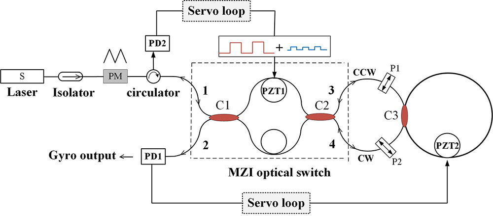
Figure 1 shows the schematic configuration of the TDM-RFOG system. All the fibers and couplers are part of the polarization maintaining operation. The light source is coupled to the slow axis of the polarization maintaining fiber. The phase modulator is used to determine the resonance line center, and a triangular wave is applied on the phase modulator[8]. After phase modulation, the light enters a optical switch to implement the light time-division input in the CW and CCW directions. The optical switch is composed of the couplers C1 and C2 and the PZT1. The coupling coefficients of the couplers C1 and C2 are designed as 0.5 and 0.5, respectively. The coupling coefficient of coupler C3 is designed as 0.05, which is used to build the fiber ring resonator (FRR). P1 and P2 are in-line polarizers. PZT1 is used to adjust the phase shift difference between the two arms of the MZI optical switch. PZT2 is used to adjust the cavity length of the FRR to make the light source frequency at the resonance line center.
In the TDM-RFOG, the optical switch is the key device that implements the light time-division input and multiplexing output in the CW and CCW directions, as shown in Table 1. In this Letter, the time slots with the phase shift difference of 0 and are called cross time-slot and through time-slot, respectively.
Δϕ
Signal light
Leaked light
0
1 to 4 (CW), 4 to 3, 3 to 2
1 to 3, 3 to 4, 4 to 1
π
1 to 3 (CCW), 3 to 4, 4 to 2
1 to 4, 4 to 3, 3 to 1
Table 1. Multiplexing output in the CW and CCW directions
At the cross time-slot, the signal light and the leaked light of the MZI optical switch are output at the 4-port and 3-port, respectively, then arrive at the 3-port and 4-port, respectively, after passing through the FRR and then, reversely, go through the optical switch and finally reach PD1 and PD2, respectively. At the cross time-slot, the output of the MZI optical switch provides the CW wave of the RFOG.
At the through time-slot, the signal light and the leaked light are output at the 3-port and 4-port, respectively, then arrive at the 4-port and 3-port, respectively, after passing through the FRR and then, reversely, go through the optical switch and finally reach PD1 and PD2, respectively. At the through time-slot, the output of the MZI optical switch provides the CCW wave of the RFOG.
Whether at the through or cross time-slot, the leaked light of the optical switch finally reaches PD2. PD2 is used to monitor the power of the leaked light of the optical switch. At the cross time-slot, the CW wave reaches PD1 and PD1 can obtain the information about the frequency deviation between the resonance line center of the CW direction and the source frequency. At the through time-slot, according to the information about the frequency deviation, the resonance line center of the CW direction moves to the source frequency by PZT2. At the same time the CCW wave reaches PD1 and PD1 can obtain the rate of rotation.
The response time of the FRR is a key parameter of the system. The switching time of light time-division input in the CW and CCW directions would be limited by the response time of the FRR. The input light field of the FRR can be written as where and are the amplitude and the center circular frequency of the input light field, respectively.
When the input light of the CW path is switched off, the electric field inside the FRR in the CW direction with respect to the time can be written as where is the coupling coefficient of C3, is the insertion loss of C3, is the traveling time in the FRR, is the cavity length, is refractive index, is the speed of light, and is the frequency of the working point. The cavity finesse can be derived as
The cavity length , the coupling coefficient , and the insertion loss . After calculation, the finesse of the FRR is 50. When the time is at , the light intensity inside the FRR is . Therefore, when the time is at , the backscattered light induced by the residual signal will not affect the performance of the TDM-RFOG.
When the input light of the CW path is switched on, the output field of the FRR in the CW direction with respect to the time can be written as
Sign up for Chinese Optics Letters TOC. Get the latest issue of Chinese Optics Letters delivered right to you!Sign up now
Figure 2 shows the output intensity of the FRR with respect to the time. After calculation, when the time is at and , the output intensity can reach 99.2% and 99.9995% of the final stable intensity, respectively. Therefore, the frequency of the square signal applied on the optical switch should be less than 100 kHz.
Figure 2.Output intensity of the FRR with respect to the time.
In the RFOG, the signal light and the backscattered light on the detector can be written as[14]where the amplitudes of the CW and CCW waves are equal, both and are the phases of the signal light, is the ensemble averaged phase of the backscattered light, and is the equivalent reflection ratio.
In the TDM-RFOG, the total intensity on the detector can be given as where is the extinction ratio of the optical switch. The suppression effectiveness of the backscattering noise including the intensity term and interference term depends on the extinction ratio of the optical switch. When the output power of the light source is 1 mW, the diameter of the FRR is 0.1 m, the cavity length of the FRR is 10 m, the finesse of the FRR is 50, and the synchronous demodulation output corresponding to is about [6]. The ratio of the FRR with the cavity length 10 m is about , so the backscattering and backreflection induced error in the RFOG is about 1(°)/s–5(°)/s[12]. When the extinction ratio reaches , the powers of the backscattered light and the interference term are about and , respectively, and the bias stability of the TDM-RFOG can reach .
Next, the relationship between the extinction ratio and the suppression effectiveness of backscattering induced noise is experimentally analyzed. Figure 3 shows the schematic configuration of the experiment. A optical switch is used to implement light time-division input in the CW and CCW directions, and the extinction ratio of the optical switch is . An in-line polarizer is inserted into the FRR to suppress the error caused by polarization fluctuations. The frequency of triangular wave applied on the phase modulator is 200 kHz, and the frequency of square signal applied on the optical switch is 5 kHz. In the comparison experiment, the optical switch is replaced by a 3 dB coupler, which can be regarded as an optical switch with an extinction ratio of 0 dB. The interference term is the dominant noise source in the RFOG[14] and, according to Eq. (6), the interference term can be reduced by in theory when an optical switch with the extinction ratio of is used. Figure 4 shows the RFOG outputs with an integration time of 1 s. The bias stability of the RFOG with an optical switch is , and the bias stability of the RFOG with a 3 dB coupler is . With an optical switch having an extinction ratio of , the bias stability is improved by 12 dB. Therefore, theoretical analysis is consistent with experimental results. In order to further improve the suppression effectiveness of backscattering induced noise, the extinction ratio of the optical switch needs to be improved.
Figure 3.Schematic configuration of the experiment.
Next, the extinction ratio of the optical switch along the slow axis is analyzed. At the 3-port and 4-port shown in Fig. 1, the output field of the optical switch along the slow axis can be given by where is the amplitude of the output field of the light source, is the phase shift difference between the two arms, and and are the coupling coefficients of the couplers C1 and C2 along the slow axis, respectively.
At the 3-port and 4-port, the output intensity of the optical switch along the slow axis can be given by where . Therefore, the extinction ratio of the switch along the slow axis can be derived as
Figure 5 illustrates that the extinction ratio of can be obtained when and are and is . In general, the phase control accuracy of the MZI optical switch is (corresponding to ), so the extinction ratio of the optical switch is about , which is not sufficient to completely suppress backscattering induced noise. Therefore, a closed loop is required to adjust to suppress the inevitable thermal drift.
Figure 5.Extinction ratio of the optical switch: .
Next, a closed loop is designed to adjust to suppress the inevitable thermal drift. When the full range voltage () of the 18 bit DA used on PZT1 corresponds to , rad is equivalent to . In order to maintain the extinction ratio greater than , a square-wave signal with an amplitude less than 16LSB is superimposed on the switching signal to monitor the power of the leaked light along the slow axis, as shown in Fig. 6(a). At the cross time-slot, the power of the leaked light reaching PD2 along the slow axis can be written as where is the square-wave signal with the frequency that is different from the switching frequency of the optical switch. The output signal of PD2 is shown in Fig. 6(b).
The output of synchronous demodulation can be derived as where is shown in Eq. (10), and is used to adjust the DA voltage on PZT1. When equals 0, the extinction ratio can be greater than .
In addition to the leaked light , the light falling on PD2 includes (the backscattering and backreflection of the signal light) and (a small part of the output signal light). The output intensity of the light source is 1 mW, and the component of at the frequency is about , so will not affect the synchronous demodulation output of PD2. The component of at the frequency is about , so will also not affect the synchronous demodulation output of PD2.
The extinction ratio of the optical switch along the slow axis will be affected by the unwanted polarization eigenstate along the fast axis. Because the polarization extinction ratio of the couplers C1 and C2 is about , when the extinction ratio along the slow axis reaches −70 dB and along the fast axis reaches , the extinction ratio along both slow and fast axes can be greater than −70 dB. According to Eq. (9), the coupling coefficients along the fast axis need to be and needs to be .
The scheme of two arms with twin polarization-axis rotated splices is proposed to make the extinction ratio along both the slow and fast axes greater than , as shown in Fig. 7. The phase shift of the upper arm along the fast axis can be given by where and are the length of the two segments of the upper arm respectively, and and are the refractive indices of the fast and slow axes, respectively. The phase shift of the upper arm along the slow axis can be given by
The effect of the temperature on the phase shift difference between the two polarization eigenstates of one arm can be given by where is the length difference between two segments of one arm and is the temperature.
The relationship between the refractive index and the temperature is . When the length difference , . And when the temperature fluctuation is controlled in the range of , can be within . Therefore can be with by controlling the temperature fluctuation in the range of . If the extinction ratio along the fast axis cannot reach , the in-line polarizers P1 and P2 shown in Fig. 1 can be used to attenuate the unwanted polarization eigenstate along the fast axis.
Based on the above analysis, the control process of the extinction ratio of the optical switch is simulated, as shown in Fig. 8. In Fig. 8, and are set to 0.4999, the amplitude of the square-wave signal is set to 0.0004 rad, and the noise of the output signal of the 18 bit DA used on PZT1 is equivalent to 5LSB. Figure 8 illustrates that the extinction ratio of the MZI optical switch can reach .
In conclusion, an RFOG with the light time-division input in the CW and CCW directions is designed. The optical switch implements the light time-division input and multiplexing output in the CW and CCW directions. The response time of the FRR is analyzed, and it is demonstrated by experiments that light time-division input in the CW and CCW directions can reduce the backscattering induced noise. The suppression effectiveness of the backscattering noise depends on the extinction ratio of the optical switch, so a closed loop is designed to adjust the phase shift difference between the two arms of the MZI optical switch to control the extinction ratio. The method using two arms of the MZI optical switch with twin 90° polarization-axis rotated splices is proposed to make the extinction ratio along both the slow and fast axes greater than .
References
[1] G. Sanders, L. K. Strandjord, J. Wu, W. Williams, M. Smiciklas, M. Salit, Ch. Narayanan, E. Benser, T. Qiu. 2017 DGON Inertial Sensors and Systems, 1(2017).
[2] G. Sanders, L. K. Strandjord, W. Williams, E. Benser, S. Ayotte, F. Costin. 2018 DGON Inertial Sensors and Systems, 1(2018).
Zongfu Hu, Zhiguo Jiang, Jinfang Wang, Su Mei. Resonator fiber optic gyros with light time-division input and multiplexing output in clockwise and counterclockwise directions[J]. Chinese Optics Letters, 2020, 18(3): 030601