Renfang Hu, Jian Chen, Faiz Wali, Shengxiang Wang, Kun Gao, Gang Liu. High efficiency positive and negative phase zone plates[J]. Chinese Optics Letters, 2017, 15(2): 020501
Copy Citation Text
We design a new kind of phase zone plates (PZPs) to improve the diffraction efficiency of soft x ray zone plates (ZPs). The design replaces blank parts of PZPs with metals of negative phase shift at the working energy, which is called as the positive and negative PZPs (PNPZPs). According to the calculation, PNPZPs have a higher maximum efficiency than conventional ZPs with the same zone width. With the help of a negative phase coefficient, it is much easier to achieve a phase shift in one period, resulting in a smaller zone height. This design can help fabricate finer PZPs to achieve a better image resolution.
Zone plates (ZPs) play an important role in the x ray spectral range as diffractive optical elements for focusing and imaging. The spatial resolution of transmission x ray microscopy (TXM) with ZPs as an objective can be 12 nm for soft x rays[1,2] and 20–30 nm for hard x rays[3–6]. Two of the most important parameters for the ZPs are their outermost zone width and zone height, because the spatial resolution depends on the outermost zone width , which can be expressed as [7], and diffraction efficiency depends on the zone height[8]. For most of the fine soft x ray ZPs, the diffraction efficiency improves with the increase of zone height. However, nanofabrication limits the achievable aspect ratio, which means that the zone height is limited when the zone width becomes narrow[9]. In other words, the diffraction efficiency is limited when the spatial resolution becomes better. For example, for nickel (Ni) ZPs having a 15 nm outermost zone width and 55 nm zone height, the detected efficiency is only [10].
The refractive index, expressed in the form , where accounts for the phase effects and is responsible for absorption, for all materials at x ray wavelengths is typically very close to unity. At the absorption edges, and simultaneously possess sharp discontinuities, giving rise to a negative value of delta[11]. The material region of conventional phase ZPs (PZPs) introduces a phase shift of while its blank region introduces a phase shift of zero. In our work, the PZP blank regions are filled with another metal with a negative phase shift at the working energy, which is the special energy range where the refraction index of the metal is negative. Our proposed design may open a breakthrough in x ray optics.
In this Letter, we design a new kind of PZP to improve the diffraction efficiency of fine soft x ray PZPs compared with conventional PZPs at the same zone height. The essence of our design is to replace transparent zones of ZPs with another kind of metal. We call this new kind of ZPs positive and negative PZPs (PNPZPs).
Sign up for Chinese Optics Letters TOC. Get the latest issue of Chinese Optics Letters delivered right to you!Sign up now
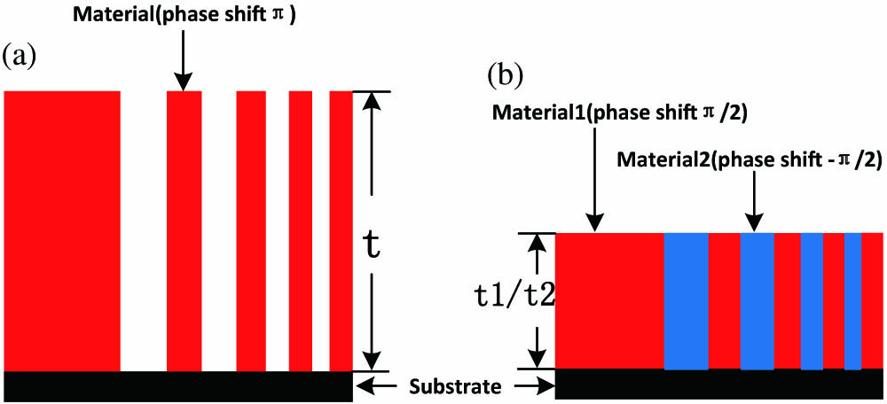
A schematic diagram is shown in Fig. 1: for the normal PZPs, two half-period zones are material rings and blank parts, while the PNPZPs consist of two kinds of material rings. Both the two half-period zones of the PNPZPs contribute to the phase shift that is not from only one of the normal PZPs. Therefore, the height of the zones to achieve a phase shift in one period can be reduced. In other words, with the same zone height (with a phase shift ) the PNPZPs has more phase shift, meaning the PNPZPs will have a higher diffraction efficiency. From another point of view, a smaller zone height leads to a smaller zone width with the same aspect ratio. Therefore, it is also possible to fabricate finer PZPs to achieve a better image resolution under current processing conditions utilizing our design.
Figure 1.Comparison of half-period zone structure between (a) the normal PZPs and (b) the PNPZPs.
The phase shifts of the two materials in PNPZPs are and , respectively, while zone heights may or may not be the same, as shown in Fig. 1(b); the difference of the phase shifts must be to achieve the maximum diffraction efficiency. The structure of PNPZPs is shown in Fig. 2; it consists of a series of concentric zone rings with radius (where is the zone index number, is the wavelength and is the focal length).
Figure 2.Schematic diagram of PNPZPs. On the left are two different material ZPs; putting them together we have PNPZPs (right), each material being the negative phase shift material that is acceptable at the working energy.
The basic fabrication principle and function of PNPZPs is similar to that of PZPs.
The refraction index of most metals is negative around a special energy range (giant resonance peaks), for example, vanadium (V) 505–517 eV, iron (Fe) 702–712 eV, Ni 845–861 eV, zinc (Zn) 1017–1028 eV, and so on, as shown in Fig. 3. The energy range of the negative refraction index lies in soft energy x rays; therefore, PNPZPs can only be used for soft x ray microscopy. Practically, not all these metals are suitable to fabricate PZPs because their giant resonance peaks are not in the frequently-used energy range. In addition, the absolute value of the negative refraction index of some metals is so small that the diffraction efficiency cannot be enhanced. V is special because its giant resonance energy is about 511.9 eV, which lies in the range of the water window (250–540 eV). Moreover, Ni is the most common metal for ZPs at the water window, because it has higher diffraction efficiency. So, V in addition to Ni is selected for fabrication of PNPZPs for energy around 511.9 eV.
Diffraction efficiency is one of the most important parameters for ZPs, so we calculate the diffraction efficiency to explain the significance and importance of PNPZPs.
Figure 3.Energy dependence of the refractive-index contributions to some metals.
The first-order efficiency of conventional PZPs can be calculated as[8]where the wavenumber, is the refractive-index decrement, is the imaginary part of the refractive index, and is the height of the PZPs. Similarly, we can deduce the first-order efficiency of the two different materials: where subscripts 1 and 2 indicate the relevant parameters of materials 1 and 2, respectively.
Figure 4 shows the relation between the zone height and the first-order diffraction efficiency based on Eq. (1) at an energy of 511.9 eV. The Ni PZPs provided the highest efficiency of 22.97% when the zone height was approximately 242 nm.
The diffraction efficiency of PNPZPs is directly related to the heights of the two materials, so we can draw a surface to describe the first-order diffraction efficiency as a function of the heights of the two metals at 511.9 eV based on Eq. (2), as shown in Fig. 5.
Figure 4.Height of zone dependence of the first-order diffraction efficiency of the Ni PZPs at 511.9 eV.
When we consider the aspect ratio of the ZPs, the thickness should be (, ), and after simply analysis from Fig. 5 we know that we have a minimum when . For convenience of fabrication, we set the height of the two metals to be the same.
Figure 6 compares the diffraction efficiency of conventional Ni PZPs and Ni–V PNPZPs as a function of different zone heights at an energy of 511.9 eV. Efficiency of this PNPZP reaches the maximum at a zone height around 140 nm, while that of ordinary Ni ZPs is about 242 nm, and the highest efficiency of PNPZPs is a bit higher than that of Ni ZPs. Therefore, at the same spatial resolution and a high diffraction efficiency, the aspect ratios of PNPZPs are much smaller than for PZPs, and the former fabrication is also easier to achieve. Similarly, at the same outermost zone width and zone height, PNPZPs and PZPs have the same aspect ratio, but the former has a higher diffraction efficiency. In the case of high spatial resolution ZPs, the outermost zone width should be thin and the corresponding zone height should be small because of fabrication limitations. For instance, Holmberg et al. manufactured an extremely high spatial resolution Ni ZPs with a 13 nm outermost zone width but only a 35 nm zone height t, using typical aspect ratios of pure Ni PZPs[7]. The theoretical diffraction efficiency of the above Ni ZPs is 1.6% while for Ni–V PNPZPs it is 4.3% at an energy of 511.9 eV with the same zone height. So, PNPZPs can improve the diffraction efficiency without increasing the zone height.
Figure 6.Theoretical first-order efficiency of ZPs as a function of the zone height at a working energy of 511.9 eV.
Here, we underline that the diffraction efficiency is not reduced by filling up blank spaces with another metal, since penetration does not play the dominant role for PZPs. Moreover, at the working energy, the phase shift of the metal is negative while the absorption coefficient is also minimum.
It is important to note that an increased diffraction efficiency is observed in a narrow energy range, e.g., only several eV. We calculate the diffraction efficiency as a function of the working energy of a 140 nm height Ni–V PNPZP and Ni PZP. The diffraction efficiency of Ni PZ at the water window is about 15%, while the diffraction efficiency of Ni–V PNPZP at an energy range from 510 to 512 eV is higher than 20%, and the efficiency of PNPZP stays higher than that of Ni ZP at a 2 eV energy resolution. For example, cell x ray imaging at the water window commonly set the energy at about 500, 520, or 511.9 eV, which have not much difference in results. So the energy range would not limit the usage of PNPZPs.
We also calculate the diffraction efficiency as a function of the working energy of a 35 nm height Ni–V PNPZP and Ni PZP. Ni–V PNPZP at an energy range from 510 to 513 eV maintains a high diffraction efficiency (more than 3%).
For most water window x ray microscopy in synchrotron radiation, chromatic dispersion is less than 0.5 eV; for example, an energy resolution for the energy range 250–2000 eV at the Shanghai Synchrotron Radiation Facility beamline BL08U, and up to 10000 at the BESSY II beamline U41-FSGM. Therefore, PNPZPs is an acceptable objective for a water window imaging system. But, as the working energy is fixed to a certain value, PNPZPs is not suitable for experiments that need to change energies, such as x ray spectromicroscopy.
The fabrication methods of conventional x ray ZPs mainly are holographic exposure, electron-beam lithography (EBL) and multilayer[12]. The fabrication method for PNPZPs is very similar to that of conventional ZPs. But PNPZPs contain two kinds of metals, so the fabrication process becomes more complex. We choose Ni–V as the metals to describe some fabrication methods for PNPZPs.
The first fabrication method is EBL; the main idea is to fabricate one common ZP with one kind of metal, and then electroplate another metal to fill in the blank part. The second fabrication method is multilayer. The basic concept of fabrication Is as follows: a glass fiber is coated with a multilayer of two different materials with different phase shifting properties and sectioned to deliver a slice, which is the new PNPZP[13–15]. Except for the method mention above, the overlay nanofabrication technique for micro ZP fabrication proposed by Chao et al. can also be used to fabricate PNPZPs[16]. Therefore, though PNPZPs need more kinds of material than conventional ZPs, they can be fabricated by available methods without difficulty.
In conclusion, a new type of PZPs based on the phase shift of metal appearing negative around absorption edges is introduced. The two half-period zones are filled with two kinds of metals, the phase shifts of which are positive and negative, respectively, at the working energy. Then we choose the Ni–V PNPZP that works at the water window energy range as the example, calculate the first-order diffraction efficiency as a function of zone height at the working energy point, and compare with the conventional PZPs. The results show that the new PNPZPs could reduce the zone heights to achieve the maximum diffraction efficiency and improve diffraction efficiency without increasing the zone height. To analyze the working energy range, we calculate the diffraction as a function of energy. Combined with the energy resolution of the x ray microscopy system, the results show that the new ZPs could be used in synchrotron radiation microscopy beamlines. Finally, several ZP fabrication methods for PNPZPs are proposed. In summary, though the PNPZPs have the working energy limit, they are still a great kind of potential ZPs.
[10] A. Holmberg, J. Reinspach, M. Lindblom, E. Chubarova, M. Bertilson, O. von Hofsten, D. Nilsson, M. Selin, D. Larsson, P. Skoglund. the 10th International Conference on X-ray Microscopy, 18(2011).
Renfang Hu, Jian Chen, Faiz Wali, Shengxiang Wang, Kun Gao, Gang Liu. High efficiency positive and negative phase zone plates[J]. Chinese Optics Letters, 2017, 15(2): 020501