Abstract
The spin Hall effect of light (SHEL) is a photonic version of the spin Hall effect in electronic systems and has been studied for more than 10 years. However, the lack of effective methods for dynamic modulation of spin-dependent splitting may hinder its applications. By introducing additional spin-orbit coupling of photons or nonreciprocal phase shift (NRPS), the magneto-optical Kerr effect may be one of the methods to alleviate the situation. Here, we experimentally reveal an enhanced and tunable SHEL in magneto-optical oxide thin films under the transverse magneto-optical Kerr effect configuration for the first time, to the best of our knowledge, which can be regarded as the magneto-optical SHEL (MOSHEL). We study the magneto-optical response of the multilayer structure and select the optimal structural parameters by the magneto-optical transfer matrix method. With a transverse magnetic field along opposite directions, an obvious SHEL shift difference of H-polarized light caused by NRPS is observed via a weak measurement method. With optimal parameters, the maximum measured shift difference of the SHEL achieves about 70 μm. The demonstrated MOSHEL phenomenon may accelerate the application of the SHEL in the field of spin photonics devices and precision metrology.1. INTRODUCTION
The magneto-optical Kerr effect (MOKE) is a classic optical phenomenon and is indispensable for industrial applications and scientific research. For instance, it has been used for magneto-optical (MO) sensing [1–3], MO isolation [4,5], and nano-magnetic technology [6,7]. MOKE in magnetic films is closely related to the strength and direction of the applied magnetic field; for different magnetic field directions, there are three kinds of Kerr effects called polar, longitudinal, and transverse MOKE (that is, PMOKE, LMOKE, and TMOKE), respectively [8]. Macroscopically, reflected light in the PMOKE and LMOKE conditions shows a polarization rotation named the Kerr rotation, and a nonreciprocal phase shift (NRPS) is introduced into reflected light in the TMOKE condition [8]. These peculiar characteristics make the magnetic field become a powerful tool to modulate other optical phenomena, such as surface plasmons [9,10] and light beam shifts [11–13].
Weak measurements use a suitable preselection and post-selection technique in the quantum system to obtain large expectation values, which makes the eigenvalues be clearly distinguished [14]. Recently, weak measurements have been successfully applied to the measurement of many weak physical phenomena, such as beam deflection [15], quantum wavefunction [16], and average trajectories of single photons [17]. In particular, weak measurements have been used in the detection of the Goos–Hänchen shift [18,19] and the spin Hall effect of light (SHEL) [20–22].
Spin-orbit coupling of photons occurs when the light beam is reflected or refracted at the interface of different media and circularly polarized components of incident linearly polarized light beams split perpendicularly to the refractive index gradient, which is called the SHEL [23]. The SHEL has been widely studied in recent years, from in-depth theoretical analysis [24–26] to experimental measurements [20–22] and even preliminary applications [27–30]. In order to realize further applications of the SHEL, it is very important to modulate it flexibly [31]. The MO effect may be one of the effective methods for dynamic control of spin-dependent splitting and has been fully studied in theory until now [13,32]. A polar magnetic field applied on monolayer graphene [32] or MO films [13,29] will cause additional spin-orbit coupling for photons and form asymmetric SHEL shifts. A transverse magnetic field introduces NRPS to reflected light on MO films and will change the spin-dependent splitting.
In this paper, we study the tunable SHEL in the TMOKE condition caused by NRPS in an MO oxide thin film both theoretically and experimentally. Here, we define the SHEL enhanced by the MO effect or controlled by an external magnetic field as the MOSHEL. We first obtain the best structural parameters through theoretical calculations and then theoretically analyze the original SHEL and spin-dependent splitting amplified by weak measurements. Finally, SHEL shifts with opposite magnetic field directions are measured via weak measurements, which are consistent with theoretical predictions.
2. THEORY AND EXPERIMENT MODELS
The schematic of the light beam and the MO oxide thin film in coordinate axes is shown in Fig. 1(a). In order to reduce the loss of reflected light and obtain high-quality light beams after weak measurement amplification and then obtain a strong MO response at the same time, we choose , cerium-substituted yttrium iron garnet (CeYIG) thin film as the MO layer rather than Fe or Co [29].
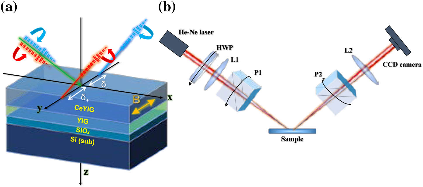
Figure 1.(a) Schematic of the SHEL on an MO oxide multilayer. A linearly polarized light beam is incident on the structure composed of , cerium-substituted yttrium iron garnet (CeYIG), yttrium iron garnet (YIG) film, and the silicon substrate, and the reflected beam splits into left and right circularly polarized light. The applied magnetic field is perpendicular to the incident plane and provided by an electromagnet. (b) Experimental setup: a half-wave plate (HWP) is used for beam intensity adjustment, and L1 () and L2 () are lenses for beam focusing and collimation, respectively. Polarizers P1 and P2 are used to determine the pre-selected and post-selected state. CCD, charge-coupled device (Coherent LaserCam HR).
Figure 1(b) shows the experiment setup widely used for SHEL detection [27–29]. The light source is a He–Ne laser with a wavelength of 633 nm, and a half-wave plate is used to adjust the light intensity received by a CCD camera. The preselection and beam focusing are completed by the polarizer P1 and a short focal length lens L1 (), respectively. When the focused H-polarized light beam is incident onto the sample, the SHEL happens. The sample is placed in an electromagnet, which is attached on a rotation stage for precise changing of the incident angle. The electromagnet is connected to a DC source, where the direction of the magnetic field can be changed when we reverse the current. A long focal length lens L2 () is used for beam collimation, and another polarizer P2 determines the appropriate post-selection state. Finally, the light intensity and beam centroid coordinate information are collected by a CCD camera.
The SHEL from a magnetic film can be described by both quantum mechanical language and standard wave optics theory. For simplicity, we choose the latter. In the case of TMOKE, a static magnetic field is applied along the direction perpendicular to the incident plane. The permittivity tensor of the MO film is [8] where is the relative permittivity of MO materials without an applied magnetic field, and the off-diagonal component is determined by the saturation magnetization of MO thin film. NRPS for -polarized light induced by the transverse magnetization can be expressed as [4] in which is the propagation constant of -polarized light in the MO layer, and is the vacuum permittivity. Then, the Fresnel reflection coefficients can be obtained by using the MO transfer matrix method [13].
Then, we calculate the SHEL shift after weak measurement amplification by the angular spectrum theory [24]. We consider the focused incident Gaussian beam from polarizer P1 (preselection) with an angular spectrum of in which is the beam waist, and the circularly polarized components of incident light can be expressed as Weak coupling is happening when incident light reflects from the multilayer structure. There is no Kerr rotation in reflected light for the TMOKE condition. Then, according to the relationship between the angular spectrum of incident beam and reflected beam, we have [24] where is the incident angle, and represent the parallel and vertical polarized states, respectively. For more accurate results, the Taylor series expansion based on an arbitrary angular spectrum component is needed, while the reflected angular spectrum is obtained, and the complex amplitude distribution of the reflected beam can be expressed as For post-selection, assume that the polarization states of P1 and P2 are expressed as and , respectively, and then the light beam transmitting through P2 has a complex electric field amplitude of where denotes the post-selection angle or amplification angle. In any given plane , the spin splitting of the beam centroid after weak measurement amplification can be obtained by the centroid integral formula where is the intensity of the light beam received by the CCD camera, and is the amplification factor. The amplification factor of is sensitive to the variation of incident angle. For H-polarized light, the modified weak value can be expressed as [33] Meanwhile, different incident angles correspond to different optimal post-selection angles.
From the above analysis, we can see that when a transverse magnetic field (strong enough) is applied to the magnetic film, a perturbation in reflection coefficients due to NRPS will cause a small change in spin-dependent splitting after weak measurements.
In order to observe an obvious influence of the magnetic field on the SHEL, we first need to choose the thickness of the CeYIG film. So, we calculate the Fresnel reflection coefficients without an applied magnetic field when is 40, 45, 50, and 55 nm, as shown in Fig. 2(a). The thickness of the YIG film is 20 nm, and permittivities are , , . The off-diagonal component of the permittivity tensor of CeYIG is at 633 nm. Figure 2(a) shows that as the thickness of CeYIG film increases from 40 to 55 nm, the amplitude of decreases first, then increases, and shows its minimum value when with an incident angle of around 73.7 deg. However, is insensitive to , which results in a large value of , and then causes a larger SHEL shift [27]. More interestingly, the MO response of our structure is also optimal at . As shown in Fig. 2(b), the relative change of reflectivity in the TMOKE condition is expressed by [1] where and represent the applied magnetic field along the and directions, respectively, and the magnetic field is strong enough (more than 500 Oe). It shows that the value of is largest when , and the variation trend is consistent with in Fig. 2(a). This means that the optimal thickness we choose can enhance both the MO effect and the SHEL, which is more conducive to the measurement of the MOSHEL shift.

Figure 2.(a) Fresnel reflection coefficient of the multilayer structure without an applied magnetic field. (b) Relative change of reflectivity caused by magnetic field directions, which is obtained by using the MO transfer matrix method.
The theoretical original SHEL shift in the TMOKE condition is shown in Fig. 3(a). It can be seen that the spin-dependent splitting is as sensitive as to CeYIG thickness. The splitting distance is relatively large when , and the incident angle is around 73.7 deg, which is consistent with in Fig. 2(a). Furthermore, from the inset () in Fig. 3(a), we can find that the SHEL has a symmetric splitting in the TMOKE condition, which is the same as the conclusion in Ref. [13].
Figure 3.(a) Original SHEL shift (left-handed circularly polarized) in the TMOKE condition for different CeYIG thicknesses. The inset shows spin-dependent splitting of left-handed and right-handed circularly polarized light when . (b) SHEL shifts with opposite magnetic fields (black solid and red dotted line) and the shift difference (green solid line) after weak measurements amplification, where .
Theoretical spin-dependent splitting (left-handed circularly polarized) in the magnetic field with opposite directions after weak measurements amplification when and is shown in Fig. 3(b). The amplified SHEL shift () is used instead of the original SHEL shift (). In order to describe the SHEL shift difference caused by the MO effect, we define a new variable of as We can find that the maximum value of [green light in Fig. 3(b)] due to an NRPS achieves about 100 μm when the incident angle is 73.9 deg. The inset of Fig. 3(b) shows the beam intensity at several different incident angles.
In addition, we also find that when the maximal original SHEL shift is about 2.5 μm in Fig. 3(a), comparable with that of the air–glass interface, and the maximal amplified shift is about 350 μm in Fig. 3(b). We can induce that in this case the amplification factor of is about 140. Thus, the original SHEL shift can be estimated as 0.7 μm approximately. Here, we should emphasize that the amplification factor of also changes with the incident angle and optical setup.
3. FABRICATION AND EXPERIMENT RESULTS
The schematic of the sample is shown in Fig. 1(a). , yttrium iron garnet (YIG) and CeYIG films were grown on a silica substrate sequentially by pulsed laser deposition (PLD), in which YIG is a seed layer. The YIG and CeYIG films were deposited by PLD equipped with a 249 nm KrF excimer laser. The bottom YIG layer was a seed layer for promoting CeYIG crystallization, which was deposited in 0.67 Pa oxygen atmosphere at 400°C. Before deposition, the based pressure of the chamber was . The laser fluence was . Then, the YIG film was rapidly thermally annealed in oxygen atmosphere at 850°C for 3 min to crystallize. After that, the CeYIG layer was deposited on the YIG layer in 1.33 Pa oxygen atmosphere at 650°C. After deposition, the sample remained at a temperature of 650°C for 30 min and was cooled down to room temperature at a rate of 5°C/min without changing the oxygen pressure.
According to the theoretical analysis above, we choose the optimum parameters for weak measurements of the MOSHEL as and the incident angle as 73.9 deg. Then, we change the post-selection angle and direction of the magnetic field. Figure 4(a) shows the measured spin-dependent splitting in different magnetic fields when the angle of incidence is 73.9 deg; it shows that the SHEL shift is insensitive to the amplification angle. A significant effect caused by the direction of the magnetic field is observed, and the maximum is approximately 70 μm. As a comparison, we also measure the SHEL at the incident angles of 55.5 deg and 80.5 deg, respectively. Theoretical analysis and experimental measurements have confirmed that is too weak to be observed at these two incident angles, so the measurement results in Figs. 4(b) and 4(c) are obtained without the magnetic field. We find the spin-dependent splitting in Figs. 4(b) and 4(c) has opposite directions, and they are both very sensitive to the amplification angle. The insets in Fig. 4 show the calculated and measured beam intensities received by the CCD camera, which are in good agreement with each other. We notice there is a minor difference between the measured and theoretical . It may be caused by the thickness deviation of the CeYIG and YIG layers, which inevitably occurs during sample preparation, especially the growth of CeYIG film by PLD. Meanwhile, the deviation of the incident angle in the adjustment of the light path during measurement can also be an important factor for the difference between measured and theoretical . Both of the above factors may affect the measurement results of the SHEL and decrease the SHEL shift induced by the magnetic field. However, we believe that the measurement deviation is tolerable. Calculation results show that the maximum original is about a few micrometers without amplification. Therefore, a measured of 70 μm after amplification by weak measurement is still prominent and more advantageous than before.
Figure 4.(a) Theoretical (solid and dashed lines) and experimental (dot marks) results of the amplified SHEL shifts in the transverse magnetic field with opposite directions, where the incident angle is 73.9 deg. (b) and (c) Amplified SHEL shifts without the applied magnetic field, where the incident angle is 55.5 deg and 80.5 deg, respectively.
4. CONCLUSION
In summary, we have studied the enhanced and tunable SHEL in MO oxide thin films under the TMOKE condition both theoretically and experimentally. We have analyzed the reflection characteristics and MO response of the multilayer structure by using the MO transfer matrix method and selected the optimal thickness of CeYIG thin film. We also calculated the original SHEL shift, amplified SHEL, and MOSHEL shifts, and then found a suitable incident angle for measurements. By applying the transverse magnetic fields along opposite directions, an SHEL shift difference of 70 μm caused by NRPS was observed via weak measurements. In addition, we have measured the SHEL shift at other two incident angles for comparison and found that the SHEL is more sensitive to the post-selection angle when there is almost no MO effect. These findings show us a novel pathway for modulating the SHEL and increase the possibility for developing new nano-photonic devices.
References
[1] J. Qin, Y. Zhang, X. Liang, C. Liu, C. Wang, T. Kang, H. Lu, L. Zhang, P. Zhou, X. Wang, B. Peng, J. Hu, L. Deng, L. Bi. Ultrahigh figure-of-merit in metal-insulator-metal magneto plasmonic sensors using low loss magneto-optical oxide thin films. ACS Photon., 4, 1403-1412(2017).
[2] N. Li, T. Tang, J. Li, L. Luo, P. Sun, J. Yao. Highly sensitive sensors of fluid detection based on magneto-optical optical Tamm state. Sens. Actuators B Chem., 265, 644-651(2018).
[3] C. C. Chan, H. F. Liew, L. H. Chen, P. Zu, C. W. Wei. Magneto-optical fiber sensor based on magnetic fluid. Opt. Lett., 37, 398-400(2012).
[4] L. Bi, J. Hu, P. Jiang, D. H. Kim, G. F. Dionne, L. C. Kimerling, C. A. Ross. On-chip optical isolation in monolithically integrated non-reciprocal optical resonators. Nat. Photonics, 5, 758-762(2011).
[5] S. Ghosh, S. Keyvavinia, W. V. Roy, T. Mizumoto, G. Roelkens. CeYIG/silicon-on-insulator waveguide optical isolator realized by adhesive bonding. Opt. Express, 20, 1839-1848(2012).
[6] M. Fronk, B. Bräuer, J. Kortus, O. G. Schmidt, D. R. T. Zahn. Determination of the Voigt constant of phthalocyanines by magneto-optical Kerr-effect spectroscopy. Phys. Rev. B, 79, 1377-1381(2009).
[7] K. Aoshima, N. Funabashi, K. Machida, Y. Miyamoto. Spin transfer switching in current-perpendicular-to-plane spin valve observed by magneto-optical Kerr effect using visible light. Appl. Phys. Lett., 91, 052507(2007).
[8] G. Armelles, A. Cebollada, A. García-Martín, M. U. González. Magnetoplasmonics: combining magnetic and plasmonic functionalities. Adv. Opt. Mater., 1, 10-35(2013).
[9] I. Razdolski, D. Makarov, O. G. Schmidt, A. Kirilyuk, T. Rasing. Nonlinear surface magnetoplasmonics in Kretschmann multilayers. ACS Photon., 3, 179-183(2016).
[10] J. B. Gonzálezdíaz, A. Garcíamartín, J. M. Garcíamartín, A. Cebollada, G. Armelles. Plasmonic Au/Co/Au nanosandwiches with enhanced magneto-optical activity. Small, 4, 202-205(2008).
[11] T. Tang, J. Qin, J. Xie, L. Deng, L. Bi. Magneto-optical Goos–Hänchen effect in a prism-waveguide coupling structure. Opt. Express, 22, 27042-27055(2014).
[12] T. Tang, J. Li, M. Zhu, L. Luo, J. Yao, N. Li, P. Zhang. Realization of tunable Goos–Hanchen effect with magneto-optical effect in graphene. Carbon, 135, 29-34(2018).
[13] J. Li, T. Tang, L. Luo, N. Li, P. Zhang. Spin Hall effect of reflected light in dielectric magneto-optical thin film with a double-negative metamaterial substrate. Opt. Express, 25, 19117-19128(2017).
[14] Y. Aharonov, D. Z. Albert, L. Vaidman. How the result of a measurement of a component of the spin of a spin-1/2 particle can turn out to be 100. Phys. Rev. Lett., 60, 1351-1354(1988).
[15] P. B. Dixon, D. J. Starling, A. N. Jordan, J. C. Howell. Ultrasensitive beam deflection measurement via interferometric weak value amplification. Phys. Rev. Lett., 102, 173601(2009).
[16] J. S. Lundeen, B. Sutherland, A. Patel, C. Stewart, C. Bamber. Direct measurement of the quantum wavefunction. Nature, 474, 188-191(2011).
[17] S. Kocsis, B. Braverman, S. Ravets, M. J. Stevens, R. P. Mirin. Observing the average trajectories of single photons in a two-slit interferometer. Science, 332, 1170-1173(2011).
[18] G. Jayaswal, G. Mistura, M. Merano. Weak measurement of the Goos–Hänchen shift. Opt. Lett., 38, 1232-1234(2013).
[19] S. Chen, C. Mi, L. Cai, M. Liu, H. Luo. Observation of the Goos–Hänchen shift in graphene via weak measurements. Appl. Phys. Lett., 110, 031105(2016).
[20] O. Hosten, P. Kwiat. Observation of the spin Hall effect of light via weak measurements. Science, 319, 787-790(2008).
[21] H. Luo, X. Zhou, W. Shu, S. Wen, D. Fan. Enhanced and switchable spin Hall effect of light near the Brewster angle on reflection. Phys. Rev. A, 84, 1452-1457(2011).
[22] Y. Qin, Y. Li, X. Feng, Z. Liu, H. He. Spin Hall effect of reflected light at the air-uniaxial crystal interface. Opt. Express, 18, 16832-16839(2010).
[23] M. Onoda, S. Murakami, N. Nagaosa. Hall effect of light. Phys. Rev. Lett., 93, 083901(2004).
[24] K. Y. Bliokh, Y. P. Bliokh. Conservation of angular momentum, transverse shift, and spin Hall effect in reflection and refraction of an electromagnetic wave packet. Phys. Rev. Lett., 96, 073903(2006).
[25] K. Y. Bliokh, F. J. Rodríguezfortuño, F. Nori, A. V. Zayats. Spin-orbit interactions of light. Nat. Photonics, 9, 796-808(2015).
[26] K. Y. Bliokh, Y. Gorodetski, V. Kleiner, E. Hasman. Coriolis effect in optics: unified geometric phase and spin Hall effect. Phys. Rev. Lett., 101, 030404(2008).
[27] X. Zhou, X. Ling, H. Luo, S. Wen. Identifying graphene layers via spin Hall effect of light. App. Phys. Lett., 101, 251602(2012).
[28] J. X. Zhou, H. L. Qian, C. F. Chen, J. X. Zhao, G. R. Li, Q. Y. Wu, H. L. Luo, S. C. Wen, Z. W. Liu. Optical edge detection based on high-efficiency dielectric metasurface. Proc. Natl. Acad. Sci. USA, 116, 11137-11140(2019).
[29] X. Qiu, X. Zhou, D. Hu, J. Du, F. Gao, Z. Zhang, H. Luo. Determination of magneto-optical constant of Fe films with weak measurements. Appl. Phys. Lett., 105, 131111(2014).
[30] T. F. Zhu, Y. J. Lou, Y. H. Zhou, J. H. Zhang, J. Y. Huang, Y. Li, H. L. Luo, S. C. Wen, S. Y. Zhu, Q. H. Gong, M. Qiu, Z. C. Ruan. Generalized spatial differentiation from the spin Hall effect of light and its application in image processing of edge detection. Phys. Rev. Appl., 11, 034043(2019).
[31] W. Zhu, M. Jiang, H. Guan, J. Yu, H. Lu, J. Zhang, Z. Chen. Tunable spin splitting of Laguerre–Gaussian beams in graphene metamaterials. Photon. Res., 5, 684-688(2017).
[32] J. Li, T. Tang, L. Luo, J. Yao. Enhancement and modulation of photonic spin Hall effect by defect modes in photonic crystal with graphene. Carbon, 134, 293-300(2018).
[33] X. Zhou, X. Li, H. Luo, S. Wen. Optimal preselection and postselection in weak measurements for observing photonic spin Hall effect. Appl. Phys. Lett., 104, 051130(2014).


