Abstract
In this Letter, we demonstrate high-quality (Q), millimeter-size, and V-shaped calcium fluoride crystalline resonators for modal modification. To manufacture such resonators, we develop a home-made machining system and explore a detailed process. With a dedicated polished container, three special polishing steps, including grinding, smoothing, and polishing, are employed to achieve the required surface smoothness, which is characterized by less than 3 nm. An ultra-high-Q factor exceeding 108 is obtained by a coupled tapered fiber. In addition, a customized packaged structure for our disk resonator is achieved. The Q maintenance and stable spectrum are realized by sealing the coupling system in a hard disk. The simple, stable, portable, controlled, and integratable device would provide great potential in optical filters, sensors, nonlinear optics, cavity quantum electrodynamics, and especially some applications that require large resonators such as gyroscopes.Optical resonators supporting whispering-gallery modes (WGMs) have become a versatile platform for fundamental studies and technological applications of light and its interactions with matter[1–4]. WGM resonators have been realized in various kinds of materials, including glass, crystal, polymer, and liquid, to meet the requirements of different applications[5]. The WGMs in the resonator guide strong light waves circulating about the edge by continuous total internal reflection (TIR). Owing to high purity and low material losses, optical resonators based on calcium fluoride () single crystals theoretically and experimentally showing a high-quality () factor, which is a desirable property, have potential applications such as optical filters, cavity quantum electrodynamics (CQED), optical parametric oscillations, nonlinear optics, and especially optical frequency comb[6]. Especially, it has extremely high permeability and a broad transmission window (130–9000 nm) from ultraviolet to infrared spectral ranges. More importantly, they do not absorb water vapor from the normal surrounding medium, resulting in the characteristic of high to be maintained for longer time than those optical resonators based on silica material.
Unlike fused silica microresonators, crystalline resonators are difficult to be prepared by thermal fusion. crystals are very difficult to be machined due to their delicate nature. Recently, a sub-millimeter resonator was realized using femtosecond laser micromachining. However, the factor only reached near 1550 nm[7]. Alternative machining technology is the single-point diamond turning, which is an ultra-precision metal cutting method capable of machining high-accuracy components[8]. The factor reported just achieved in the single-point diamond turning experiment[8]. Because of features such as low hardness, breakability, anisotropy, and high thermal expansion coefficients, fabrication of resonators with a high- factor is still a challenge in ultra-precision machining. Though the factor of crystalline resonators has reached an ultra-high value in current research[9], the customized machining system and dedicated fabrication design for resonators have not been investigated.
To our knowledge, the resonant property is sensitive to the surroundings outside the resonator, such as thermal fluctuations resulting from ambient temperature variation[10]. Moreover, to achieve a high coupling efficiency, the fiber taper or a coupling prism is commonly used to excite the WGMs of the microresonator[11], which makes the coupling system fragile and lack robustness. Previously, a packaged microresonator coupled with a coupling prism has been realized as a commercial product of the OEWaves company[12]. More recently, we have demonstrated a packaged microsphere device without embedding it into the polymer, thus leaving the WGM evanescent fields available for environmental sensing[10].
Sign up for Chinese Optics Letters TOC. Get the latest issue of Chinese Optics Letters delivered right to you!Sign up now
In this Letter, we experimentally demonstrate the fabrication technique and packaged device for crystalline resonators with modal modification. We develop the fine polishing method with abrasive particles based on a diamond turning and polishing apparatus. The rim of the disk resonator is characterized by less than 3 nm surface roughness, leading to factors in excess of being achieved. The maintenance of and a stable spectrum are realized by packaging the coupling system in a sealed hard disk. The portability and robustness of the packaged structure make it strikingly attractive and illustrate its potential in practical resonator filters, lasers, frequency comb, and especially some applied fields that require large resonator-like optical gyroscopes.
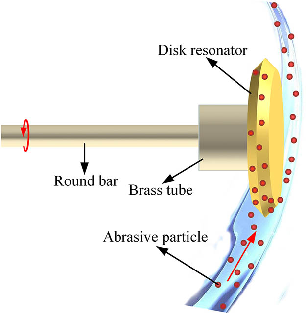
Figure 1 illustrates the fabrication method for the designed disk resonator. We manufacture resonators with abrasive particles. They are fabricated in a home-made diamond polishing apparatus. Commercially available -cut disks with a diameter of 12 mm and a thickness of 1 mm were used in our experiments. Due to the soft texture of crystalline materials, residual growth stress inside, very high coefficient of thermal expansion, mechanical properties directionality, and selectivity to polishing agents, the processing process may be easily influenced by external perturbations such as thermal fluctuation, air flow, and vibration. It is very difficult to obtain high-integrity nano-roughness of a crystal surface. To solve these problems, we built a set of ultra-precision machining systems. Figure 2 shows the full polishing system for the disk resonator. All parts include the main machining system, the circulation system, the air-supply system, and the servo system.

Figure 1.Schematic drawing of the method of fabricating the designed disk resonator.
Figure 2.Schematic of the experiment setup for the full polishing system for the disk resonator. The customized machining system is used to manufacture the disks together with the circulation system, the air-supply system, and the servo system.
Specifically, the machining system includes an air-bearing motor, a dedicated polishing container, a three-dimensional translational platform, and a charge-coupled device (CCD) with a microscope objective, as shown in Fig. 2. The air-bearing motor (Canon AB-50 R) greatly lowers the friction and vibration generated by the motion process, ensuring that the spindle could provide stable rotation with extremely low noise and vibration. It provides a powerful guarantee for the fabrication of high- disk resonators. The polishing container is customized to make it convenient to put abrasive particles into it. We use the polishing container for the benefit of developing different polishing steps by changing abrasive particles. The three-dimensional translational platform is made up of a motorized x−y stage and a manual stage. The motorized x−y stage controlled by two electric machineries controls the movement of the polishing container. The manual stage is to keep the abrasives and the disk resonator in touch, resulting in the rim of the disk being polished. On no account can we ignore the immense value of the CCD, which is to observe and monitor the surface of the rim of the disk in real-time. That is a key to make sure the morphology of the surface fabricated is homogeneous. In addition, the flow rate and temperature of these abrasive particles can be adjusted by the circulation system. The air-supply system is to support clean air for the air-spindle motor. The servo system is to transmit and receive signals for controlling the motorized x−y stage. In the servo system, the upper computer is used to start and monitor the motion controller for offering the drive signal to control the electric machinery via a linear actuator. Moreover, the feedback circuit provides a translated feedback signal to the motion controller by an encoder.
To begin polishing, the disk was mounted on an aluminium round bar to manipulate the disk. Another workpiece of brass tubing was attached into the round bar to increase the contact area for the adhesive. Next, the round bar was mounted onto the collet chuck of our polishing apparatus, which was held on the air-bearing spindle. Subsequently, three special polishing steps, including grinding, smoothing, and polishing, were employed with the polished container, where sand paper, diamond compound, and diamond suspension were selected, respectively. Finally, the disk was ground, and it polished the abrasive particles of diamonds. Each step was completed by observing the surface with the help of the CCD to determine whether to enter the next step. In the process of grinding and polishing, temperature, pressure, and other conditions were strictly controlled to avoid popping and chipping to achieve the required surface smoothness. A cleaning process performed after each step was indispensable for removing contaminants remaining on the surface of the disk.
It is worth stressing, in the process of grinding, it allowed us to reshape the disk rim and eventually get a V-shaped rim, as shown Fig. 3. During the smoothing and polishing process, diamond compound and diamond suspension were applied to the polishing flannel. The high-speed rotating resonator is ground by the diamond particles adsorbed on the polishing flannel to achieve grinding and polishing of the surface of the resonator. In general, the time of the first step grinding was the highest among all the steps. More time over speed was needed in grinding to make sure to bring out as few impurities as possible. The effect of grinding was to shape, but many cracks were generated. A relatively flat surface could be achieved after smoothing. The third step of polishing was the most critical among all of the steps. The high- crystalline resonator could be obtained after the step polishing. In order to prevent particles in the air from adhering to the disk resonator and causing uncleanness loss, the polishing process of the disk resonators needs to be performed in a clean room environment.
Figure 3.(a), (b) Experimental photograph of the disk resonator after grinding and polishing. The diameter of the disk resonator after polishing. (c)–(e) The simulated light-field distribution of the disk resonator with thickness for the transverse electric (TE) mode.
It should be noted that the motivation for V-shaped disk resonators stems from three reasons, as summarized below. (i) The primary reason is that the modified mode will become more concentrated, which can lead to enhanced energy density based on the calculated mode analysis with a finite element method (COMSOL Multiphysics), as shown in Fig. 3(e). (ii) The dispersion of a microresonator is obtained from the geometrical and material dispersion, where the geometrical dispersion of the resonator is tailored by designing the cross-sectional shape. The engineering of modal modification is convenient for designing a resonator for dispersion control to generate an optical frequency comb[13]. (iii) The controlled geometry for the V shape will decrease the contact area between the disk and abrasive particles. The smaller contact area can make the polishing process faster to obtain a fine surface. However, the geometric shape of our disk resonator after polishing is not the standard V shape, but a trapezoid-like shape, whose field distribution is shown in Fig. 3(d). It should be noted that the geometric shape of our disk resonator after polishing is not a standard trapezoid-like shape but presents a curved surface.
As it has been validated by previous reports[14,15], the factor of a WGM resonator mainly depends on the surface roughness, while the scattering loss of the disk can be ignored, because the size is a few tens of millimeters, and the absorption coefficient is small, near the infrared wavelength. To evaluate the roughness of the fabricated surface, we observe the rim of the disk experimentally under a white light phase-shifting profilometer. Figure 3 shows the surface profile of the measured disk. The factor can be calculated by surface scattering factor, , where is the resonant wavelength, is the diameter of our disk resonator, is the measured surface roughness, and is the correlation length along the direction according to Ref. [15]. Among them, decides the resonance transmission scattering loss in the disk resonator. As shown in Fig. 4, the surface roughness is in the range of −3–3 nm along the axis direction after fitting in the detection vision-field size. The value of the mean peak height is only 0.83 nm. The result is calculated using our disk parameters for setting these parameters, which are set as , , , and .
Figure 4.(a) Measured Newton fringes periodicity for disk resonator after polishing. (b) Three-dimensional profile of surface roughness in the detection vision-field size. (c) The surface roughness along the detected axis direction.
The WGMs guide the optical light inside the disk, circulating the TIR constantly, and then form a steady resonance state. However, the light in WGMs is tightly confined. If no light is coupled out of the resonator, there is no trivial way to couple light into it. An effective solution for efficient energy exchange (coupling) is offered by the evanescent field, such as tapered fiber, waveguide, and prism[11]. Here, we fabricated a tapered fiber[16] using the “heat-and-pull” method to couple light into the disk resonator. The waist part of the tapered fiber was significantly thinned with a diameter of about . Additional benefits are that the tapered fiber allows not only alignment and focusing of the input light but also collecting of the output light. The tapered fiber also allows for integration of a resonator-tapered coupling system with other fiber optical systems easily, due to the fact that tapered fibers are basically just modified optical fibers.
Then, for measuring the resonance of WGMs, we measured the factor of the fabricated disk resonator further. We used a resonant transmission spectrum measurement setup consisting of a tunable laser, a polarization controller, a coupling system, a photodetector (PD), and a digital oscilloscope, as shown in Fig. 5. The tunable laser in the 1550 nm wavelength band (Newfocus TLB 6728) was controlled and scanned by a function generator. The polarization controller was used in the polarization state of the laser beam. Then, the output was detected by a PD. Finally, the transmission spectrum was recorded with a high-resolution digital oscilloscope. The separation between the disk resonator and the tapered fiber was controlled by a precision translation stage. In our experimental measurements, the resonator was in contact with the surface of the disk to enhance the robustness based on physical contact. We also monitored the disk and the tapered fiber from the top side by using a CCD camera.
The coupling system is composed of separate devices, including the disk resonator and the tapered fiber, which makes it fragile and hard to be portable and integratable. Additionally, a clean environment is necessary to perform the experiment, protecting the coupling system from the environmental perturbations. For these purposes, to promote disk-taper coupling into practical applications, we designed a packaged structure, where the coupling system was controlled without a precision translation stage, as shown in Fig. 6. In our packaged structure, a customized mechanical component was used to connect the coupling system and a standard hard disk with the dimensions of , in which there are activated carbons to remove the contaminated particles around the coupling system region. The disk resonator was put on the base plate after being taken down from the round bar. The tapered fiber was controlled by contacting it with a glass slide. With the help of the mechanical component, we can manipulate the disk resonator and the tapered fiber separately to keep them in contact for improving robustness. Thus, the coupling system was well-sealed in the hard disk using two optical fiber splices.
Figure 5.(a) Schematic of the experimental setup used for measuring the resonance of the disk resonator. PD is photodetector. (b) The disk resonator after polishing. (c), (d) Experimental photographs of the coupling system for the disk resonator and the tapered fiber.
Figure 6.Drawing of the packaged disk-taper coupling system in a sealed hard disk. The red arrows illustrate flexible degrees of freedom in the customized mechanical component.
We next measured the transmission spectra of the fabricated disk by the measurement setup in Fig. 5. As shown in Fig. 7(a), it can be seen that effective spectra mean that the WGMs in our disk resonator were effectively excited by the tapered fiber. That confirms that the evanescent fields of the resonator and tapered fiber have overlapped significantly. Note that our disk resonator exhibits a very rich spectra with a considerable amount of modes, which is useful in nonlinear optics, CQED studies, and especially an optical frequency comb[6]. It should be noted that a factor of up to has been demonstrated by the stretched-out spectrum. Such a high- factor also means that an ultra-narrow linewidth filter has been achieved[14]. Besides, using WGM optical microresonator-based sensors having ultra-high- factors can result in high-resolution sensor devices[10,17]. More importantly, it is also stable in normal atmospheric conditions.
Figure 7.Transmission spectra of disk-taper coupling system (a) before packaging and (b) after packaging.
It is important to point out that the factor is a direct measure of the ability of the resonator to confine and store light. It is one of the most important properties of optical resonance in any kind of geometrical resonator. For the case of our microdisk resonator, the factor is explicitly determined by the following equation[18,19]: , corresponding to an overall photon lifetime and resonance linewith , where is the resonant frequency of the WGM. The external (or coupling) factor is determined by the coupling condition of the microdisk resonator and the tapered fiber. The intra-resonator losses are characterized by the intrinsic factor in order to consider the intra-resonator volumetric losses , radiation losses , and surface scattering roughness , respectively[20]. is expressed as , and was calculated from these parameters, where is the refractive index of , and is material absorption loss at . is relevant to the size of the microdisk resonator, and the radiation losses can be ignored for resonators with a radius of as . Besides, is associated with the measured surface roughness. Consequently, to obtain the factor with the highest precision, should be as close as possible to . It can be concluded that the intra-resonator volumetric losses () were the main limitation on the factor. There is no doubt that the measured factors have been reduced based on the calculated results. Here, we know that does not influence . Even though the value of the highest measured factor has reached , the coupling condition and the measured setup may result in a limitation on the factor obtained based on the calculated theoretical result (). The deterioration partly results from over-coupling, because the disk resonator maintains contact with the tapered fiber. Moreover, improving the measured setup is expected to improve the surface roughness and the performance of the factor[9,20,21].
Finally, we measured the transmission spectra of the fabricated disk after packaging. As shown in Fig. 7(b), it is obvious that the resonant spectrum and ultra-high- factors were well-maintained. A factor as high as was still obtained in the packaged coupling structure. The robustness of the packaged structure can also be improved to obtain a stable spectrum while maintaining contact between the resonator and the tapered fiber. In the sealed hard disk, it makes our coupling system isolated from the surroundings so that the -spoiling factors, such as dust in the environment, are excluded. As a result, a factor of about was preserved for at least a few months. Particularly, it is convenient to be portable to put the coupling system in any location. It is also easy to integrate in other optical systems and microwave photonics systems. To further promote the packaged structure in practical applications, we plan to put a tunable distributed feedback laser, a photodiode detector, thermostatic equipment, and some opto-electronic processors into our sealed hard disk in our next study.
In summary, the fabrication process and packaged structure for V-shaped disk resonators with modal modification have been studied by a polishing method with abrasive particles. Three polishing steps, including grinding, smoothing, and polishing, were employed in a home-made air-bearing spindle system, where a disk resonator with a factor up to was successfully achieved. Moreover, an excellent performance to maintain high was realized by sealing the coupling system in a hard disk. The novelty of our idea will provide potential applications in many fields and promote the development of WGM-based practical devices. We especially believe that this portable, tunable, integratable, and robust device can be used in optical filters, CQED, optical frequency combs, and optical gyroscopes in various environments.
References
[1] K. J. Vahala. Nature, 424, 839(2003).
[2] S. Yang, Y. Wang, H. Sun. Adv. Opt. Mater., 3, 1136(2015).
[3] W. Xu, C. Xu, F. Qin, Y. Shan, Z. Zhu, Y. Zhu. Chin. Opt. Lett., 16, 081401(2018).
[4] Z. Pan, C. Zhang, C. Xie, Y. Zheng, H. Li, J. Tang, J. Liu. Chin. Opt. Lett., 16, 040601(2018).
[5] K. D. Heylman, K. A. Knapper, E. H. Horak, M. T. Rea, S. K. Vanga, R. H. Goldsmith. Adv. Mater., 29, 1700037(2017).
[6] I. S. Grudinin, N. Yu, L. Maleki. Opt. Lett., 34, 878(2009).
[7] J. Lin, Y. Xu, J. Tang, N. Wang, J. Song, F. He, W. Fang, Y. Cheng. Appl. Phys. A, 116, 2019(2014).
[8] Y. Mizumoto, H. Kangawa, H. Itobe, T. Tanabe, Y. Kakinuma. Precis. Eng., 49, 104(2017).
[9] A. A. Savchenkov, A. B. Matsko, V. S. Ilchenko, L. Maleki. Opt. Express, 15, 6768(2007).
[10] Y. Dong, K. Wang, X. Jin. Appl. Opt., 54, 277(2015).
[11] Y. Zhan, T. Zhou, B. Han, A. Zhang, Y. Zhao. Nanoscale, 10, 13832(2018).
[12] V. Ilchenko, E. Dale, W. Liang, J. Byrd, D. Eliyahu, A. Savchenkov, A. Matsko, D. Seidel, L. Maleki. Proc. SPIE, 7913, 79131G(2011).
[13] Y. Nakagawa, Y. Mizumoto, T. Kato, T. Kobatake, H. Itobe, Y. Kakinuma, T. Tanabe. J. Opt. Soc. Am. B, 33, 1913(2016).
[14] H. Wan, H. Li, H. Zhu, J. Xu, Y. Lu, J. Wang. Chin. Opt. Lett., 14, 112302(2016).
[15] M. L. Gorodetsky, A. D. Pryamikov, V. S. Ilchenko. J. Opt. Soc. Am. B, 17, 1051(2000).
[16] H. Guo, L. Jin, J. Ma, B. Guan. Chin. Opt. Lett., 15, 072301(2017).
[17] N. Lin, L. Jiang, S. Wang, L. Yuan, Q. Chen. Chin. Opt. Lett., 10, 052802(2012).
[18] M. Wang, X. Jin, F. Li, Y. Zhang, K. Wang. J. Infrared Millim. Waves, 37, 284(2018).
[19] M. Wang, X. Jin, F. Li, B. Cai, K. Wang. Opt. Commun., 427, 70(2018).
[20] I. S. Grudinin, V. S. Ilchenko, L. Maleki. Phys. Rev. A, 74, 063836(2006).
[21] M. Shen, M. Ye, Q. Lin, R. Yang, X. Lin. Chin. Opt. Lett., 14, 021402(2016).