Abstract
Microwave Frequency Comb (MFC) has the unique advantage of simultaneously providing multiple continuous microwave signals and then plays an important role in some application fields such as satellite communication, remote sensing, distance measurement, and anti-interference detection. At present, sustained efforts have been paid to explore novel techniques to generate the MFCs signal with adjustable comb distance, pure comb line, power balance and broad bandwidth. In this work, a system scheme for generating broadband tunable MFC based on a modulated optical injection Semiconductor Laser (SL) is proposed and experimentally investigated. First, via a distributed feedback semiconductor laser (DFB-SL1) strongly modulated by a single-tone electrical signal, a seed Optical Frequency Comb (OFC) including a few comb lines can be obtained. Next, the seed OFC is sent into a phase modulator driven by the same single-tone electrical signal as that loaded on the DFB-SL1, thus a promoted OFC with more comb lines can be obtained. Finally, the promoted OFC is injected into another DFB-SL (DFB-SL2), except the regenerated injection OFC, another sub-OFC can be observed located nearby the red-shifted central wavelength of DFB-SL2. In this case, the whole OFC can be regarded as a combination of two sub-OFCs, and then a broadband MFC can be obtained through converting the output of DFB-SL2 into electrical signal by a photo-detector. The experimental results show that, by utilizing a single-tone electrical signal with a frequency of 2.9 GHz, under optimized injection power and frequency detuning between two DFB-SLs, an MFC with 55.1 GHz bandwidth within a ±5 dB amplitude variation can be obtained, where the phase noise of each comb line is maintained below -98.66 dBc/Hz at 10 kHz frequency offset. Through varying the frequency of the single-tone electrical signal and selecting matched operating parameters, the comb spacing of generated broadband MFC can be tuned. Also, the variations of optimized MFC bandwidth with the frequency detuning Δf and injection power Pinjare analyzed. For -9.0 GHz≤Δf ≤3.6 GHz, there is only one comb line within a ±5 dB amplitude variation calculated from DC, and the MFC bandwidth maintains at 2.9 GHz. For 4.8 GHz ≤ Δf ≤ 37.4 GHz, with the increase of Δf, the minimum comb line interval between two sub-OFCs is periodically varied within [0, fmod], and meanwhile the intensity of each comb is also varied. Therefore, the bandwidth of generated MFC behaves a complex varied trend. The maximum bandwidth is about 55.1 GHz obtained under Δf=37.4 GHz. For Δf >37.4 GHz, the bandwidth of the generated MFC is relatively small due to too far apart between two sub-OFCs. Considering the red-shift induced by the optical injection, the beat frequency is not located at the frequency detuning between the two DFB-SLs. Besides frequency detuning Δf, injection power Pinjis another key parameter. With the increase of the injection power, the red-shift is more severe, and higher frequency comb lines will be enhanced, which leads to the variation of the distribution of MFCs. For a fixed Δf=37.4 GHz, with the increase of Pinj, the MFC bandwidth first increases, after reaches its maximum value of 55.1 GHz, and then decreases.0 Introduction
Semiconductor Lasers(SLs)can be driven into diverse dynamical states after introducing external perturbation such as current modulation[1],optical injection[2-4],optical feedback[5-7],and photoelectric feedback[8-9]. Such nonlinear dynamics states can be applied to many fields,including chaotic communication[10-12],random number generation[13-15],reservoir computing[16-18],Optical Frequency Comb(OFC)[19-21],and Microwave Frequency Comb(MFC)generation[22-23],etc.
MFC plays an important role in satellite communication,remote sensing and anti-interference detection[24-27] due to its unique virtue of providing multiple continuous microwave signals simultaneously. Therefore,different acquisition methods of MFCs have aroused wide concerns,where the schemes based on the nonlinear dynamic states of SLs have been proposed for generating MFC. In 2009,based on an SL injected by a regular pulse from another SL under photoelectric feedback,JUAN Yushan et al experimentally generated an MFC with a comb spacing of 990 MHz and a continuous bandwidth of 20.0 GHz within a ±5 dB amplitude variation [28]. In 2017,based on a current modulated SL under Continuous Wave(CW)optical injection,our group experimentally generated an MFC with a bandwidth of 57.6 GHz within a 5 dB amplitude variation. The Single Sideband(SSB)phase noise of each comb lines is lower than -86.00 dBc/Hz @ 10 kHz[29]. However,the low frequency region spanning from 0 GHz to 8.4 GHz is excluded since the comb lines within this region possess extremely strong power relative to other comb lines. In 2018,based on a SL subject to a regular pulse injection from a current modulated SL,our group proposed and experimentally another scheme for generating MFCs,the continuous bandwidth is defined as the continuous frequency range within a ±5 dB amplitude variation calculated from DC arrives at 33.6 GHz,and the SSB phase noises of all comb lines are decreased to a level below -90.90 dBc/Hz @ 10 kHz [30]. Moreover,the comb spacing of the generated MFCs can be continuously adjusted from 1.0 GHz to 5.5 GHz. In 2020,ALMULLA M proposed a generation scheme of MFC based on a SL optically injected by another SL under strong intensity-modulation,and the simulated results show that a MFC with a comb spacing of 3.0 GHz and a bandwidth of 51.0 GHz within a ±5 dB amplitude variation can be obtained and the comb spacing can be continuously tuned between 1.0~10.0 GHz[31]. In the same year,ZHAO Wu et al experimentally demonstrated a scheme for generating MFC based on an integrated mutually coupled distributed feedback SL[32]. After excluding the comb lines within the region of(0,8.0 GHz)due to their too strong power,the continuous bandwidth arrives at 40.0 GHz(from 8.0 GHz to 48.0 GHz)within a ±5 dB amplitude variation,and the SSB phase noises of all comb lines are lower than -73.33 dBc/Hz @10 kHz.
For practical applications,it is expected that MFCs possess tunable comb spacing and large continuous bandwidth calculated from DC. Based on our previous work[30],through further introducing phase-modulation technique,we proposed and experimentally demonstrated a novel scheme for acquiring tunable MFCs with a larger continuous bandwidth. The experimental results show that,after introducing phase-modulation technique,the performances of generated MFCs can be improved,and the continuous bandwidth can be extended to 55.1 GHz(from DC to 55.1 GHz)within a ±5 dB amplitude variation. In addition,the influences of some critical parameters on the performances of generated MFC are analyzed systematically.
1 Experimental setup
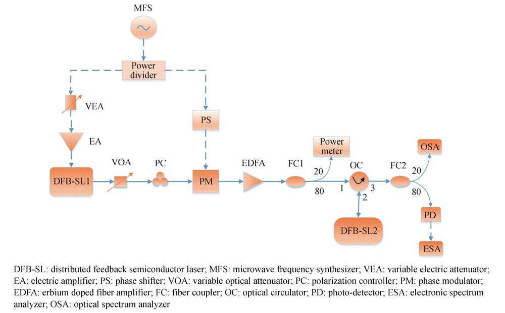
Fig. 1 shows a schematic diagram of our proposed experimental system for generating MFC,in which two commercial 1 550 nm DFB-SLs are utilized. Each laser is driven by a high stability and low noise current temperature controller(ILX-Lightwave,LCD-3724C),and the accuracies of current and temperature are 0.01 mA and 0.01 ℃,respectively. A driving single-tone electrical signal provided by a microwave frequency synthesizer(MFS,Agilent E8257C),is divided into two parts by a 50/50 power divider. One part is loaded into DFB-SL1 after passing a Variable Electrical Attenuator(VEA)and an Electrical Amplifier(EA,Agilent 83006A),and the other part is sent to a Phase Modulator(PM,Ixblue MPZ-LN-20)through a Phase Shifter(PS,Model 6705K). The PS is utilized to realize the phase matching. Under large signal current modulation,DFB-SL1 can output a seed OFC including a few comb lines,which is sent to PM after passing through an Variable Optical Attenuator(VOA)and a Polarization Controller(PC)for generating an promoted OFC with more comb lines. Next,the promoted OFC output from PM is injected into DFB-SL2 after an Erbium Doped Fiber Amplifier(EDFA),a 20/80 fiber coupler(FC1)and an Optical Circular(OC). The 20% part of FC1 is connected with an optical power meter for measuring injection power Pinj. Finally,the output optical signal from DFB-SL2 is divided into two parts by another 20/80 fiber coupler(FC2). The 20% part is sent to an optical spectrum analyzer(OSA,Aragon Photonics BOSA lite +,20 MHz resolution)for monitoring optical spectrum,and the 80% part is converted into electrical signals by a photo-detector(PD,U2T-XPDV3120R,75.0 GHz)for generating MFC. The performances of generated MFC can be analyzed through recording power spectrum and SSB phase noise curve by an electrical spectrum analyzer(ESA,R&S®FSW,67.0 GHz bandwidth).

Figure 1.Experimental setup for generating tunable broadband MFC
2 Results and discussion
Fig. 2 gives Power-Current(P-I)curves(upper row)and relaxation oscillation frequencies(below row)as a function of bias current for free-running DFB-SL1(left column)and DFB-SL2(right column)respectively. The circles and lines in(c)and(d)represent measured values and fitted values respectively. The temperature of DFB-SL1 and DFB-SL2 is set at 17.91 ℃ and 20.90 ℃,respectively. During the following experiment,the temperature of DFB-SL1 is fixed at 17.91 ℃,and the frequency detuning Δf between the two DFB-SLs is adjusted by changing the temperature of DFB-SL2. As shown in this diagram,the threshold current(Ith)is 8.50 mA for DFB-SL1 and 9.00 mA for DFB-SL2. In this experiment,the bias current of DFB-SL1 and DFB-SL2 is stabilized at 25.00 mA and 23.00 mA,respectively. Under this case,the relaxation oscillation frequency of DFB-SL1 and DFB-SL2 is 8.9 GHz and 7.6 GHz,respectively.
Figure 2.Experimentally measured power-current curves and relaxation oscillation frequencies as a function of bias current for free-running DFB-SL1 and DFB-SL2,respectively
First,a single-tone electrical signal with large amplitude is loaded on DFB-SL1 for generating a seed OFC. Fig. 3(a)displays the optical spectrum of the seed OFC under modulation frequency fmod=2.9 GHz and modulation power Pmod=12 dBm,and the corresponding power spectrum is presented in Fig. 3(b). In this work,referring to Refs.[28-32],the MFC bandwidth is defined as the continuous frequency range within a ±5 dB amplitude variation calculated from DC. As shown in this diagram,under a large signal current modulation,the output of DFB-SL1 is a narrow-band OFC. Correspondingly,there are few comb lines emerging in the power spectrum. Next,the seed OFC is sent to a PM driven by the same single-tone electrical signal as that loaded on DFB-SL1. The optical spectrum and power spectrum output from PM are given in Fig. 3(c)and(d). Obviously,a promoted OFC with more comb lines is generated due to high-order sidebands stimulated by PM. However,from Fig. 3(d),it can be seen that the comb lines are still few,which is similar with that in Fig. 3(b). Finally,the promoted OFC is injected into DFB-SL2,and the optical spectrum and power spectrum are displayed in Fig. 3(e)and(f)under frequency detuning Δf=37.4 GHz and injection power Pinj=6.8 mW. As shown in Fig. 3(e),except the regenerated injection OFC,another sub-OFC can be observed located nearby the red-shifted central wavelength of DFB-SL2(λs). Under this case,the whole OFC can be regarded as the combination of two sub-OFCs. After photoelectric conversion by a PD,a broadband MFC can be obtained,and the largest bandwidth of the MFC can be arrived at 55.1 GHz(from DC to 55.1 GHz)within a ±5 dB amplitude variation(Fig. 3(f))under a phase shift of 30.9°. In the following discussions,the phase shift is fixed at this value.
Figure 3.Optical spectra(left column)and power spectra(right column)output from DFB-SL1,PM and DFB-SL2. The gray curves in power spectra denote the noise floor,and the resolution bandwidth(RBW)of ESA is 100 kHz
In order to characterize the purity of comb lines of the generated MFCs,we measured the SSB phase noise curves of the comb lines,where the operating parameters are taken as the same as those in Fig. 3(e)and(f). Fig. 4(a)shows the SSB phase noise curves for fmod(red curves),13fmod(blue curves)and 22fmod(black curves)comb lines. It can be seen that a higher order comb line will induce a stronger SSB phase noise. Figure 4(b)is the SSB phase noise at 10 kHz frequency offset of fmod,4fmod,7fmod,10fmod,13fmod,16fmod,19fmod and 22fmod comb lines. The SSB phase noise of the first comb line is the smallest,which is about -110.50 dBc/Hz @ 10 kHz. With the increase of the comb line order,the SSB phase noises generally show an upward trend. For 19fmod comb line,which is the highest order comb line included in the bandwidth,the SSB phase noise is about -98.66 dBc/Hz @ 10 kHz. Therefore,the SSB phase noises of all comb lines included in the 55.1 GHz bandwidth can be guaranteed below -98.66 dBc/Hz @ 10 kHz.
Figure 4.SSB phase noise curves for fmod(red curves),13fmod(blue curves)and 22fmod(black curves)come lines,and SSB phase noises at 10 kHz frequency offset of representative fmod,4fmod,7fmod,10fmod,13fmod,16fmod,19fmod and 22fmod comb lines
Above results are obtained under the case that the operating parameters fmod, Pinj and Δf are taken optimized values. Based on the results in Fig. 3,in order to generate a high-quality MFC,the red-shifted central wavelength(λs)of DFB-SL2 should locate at one of the high-order sideband of the promoted OFC. Since λs is depended on Pinj and Δf,Pinj and Δf should be two key parameters to affect the performances of generated MFCs. Figure 5 shows the optical spectrum and power spectrum output from DFB-SL2 under(fmod,Pmod)=(2.9 GHz,12 dBm)and Pinj=6.8 mW with Δf=2.4 GHz,34.0 GHz,35.1 GHz,and 53.4 GHz,respectively,where the gray curves in power spectra denote the noise floor,and the resolution bandwidth(RBW)of ESA is 100 kHz. As shown in Fig. 5(a)and(b),for a relatively small frequency detuning Δf=2.4 GHz,most of comb lines in two sub-OFCs overlap. As a result,the bandwidth of generated MFC is small. Fig. 5(c)and(d)are the optical spectrum and power spectrum under Δf=34.0 GHz. It can be seen that,λs is locked to high-order sidebands of promoted OFC,and meanwhile the intensities of comb lines are appropriate. Therefore,the MFC possesses a relatively large continuous bandwidth. For Δf=35.1 GHz(Fig. 5(e)and(f)),λs is located at the middle of two high-order sidebands of promoted OFC. As a result,there are some sub-harmonics appearing in the power spectrum. For a too large Δf=53.4 GHz(Fig. 5(g)and(h)),since two sub-OFCs separate too far,the generated MFC possesses weak amplitude flatness.
Figure 5.Optical spectra(left column)and power spectra(right column)output from DFB-SL2 with different Δf
In order to show the influence of Δf on the bandwidth of generated MFC,Fig. 6 displays the bandwidth varied with Δf under(fmod,Pmod)=(2.9 GHz,12 dBm)and Pinj=6.8 mW. For -9.0 GHz ≤Δf ≤3.6 GHz,the MFC bandwidths maintain at 2.9 GHz,i.e. there is only one comb line within a ±5 dB amplitude variation calculated from DC. For 4.8GHz ≤Δf ≤37.4 GHz,with the increase of Δf,the bandwidth of MFCs behave a oscillation trend. The maximum bandwidth is about 55.1 GHz obtained under Δf=37.4 GHz. For Δf >37.4 GHz,the bandwidth of the generated MFC is relatively small due to too far apart between two sub-OFCs. The reason for such a varied trend may be explained as follow. As mentioned above,λs is depended on Δf,and therefore the sub-OFC nearby λs will shift when Δf is varied. With the increase of Δf,the minimum comb line interval between two sub-OFCs is periodically varied within[0,fmod],and meanwhile the intensity of each comb is also varied. Therefore,the bandwidth of generated MFC behaves complex varied trend. Additionally,the definition of bandwidth adopted in this work is another factor to result in the severe oscillation within 4.8 GHz≤Δf ≤37.4 GHz.
Figure 6.Bandwidth as a function of frequency detuning Δf
Besides frequency detuning Δf,injection power is another key parameter. We fix Δf at 37.4 GHz and inspect the influence of Pinj on the bandwidth of generated MFC,and the results are given in Fig. 7. Here,(fmod,Pmod)=(2.9 GHz,12 dBm),which is the same as that used in Fig. 6. As shown in this diagram,with the increase of Pinj,the MFC bandwidth first increases,reaches its maximum value of 55.1 GHz,and then decreases. Such a varied trend is similar with that reported in Ref.[30],and the physical mechanism is the same as that in Ref.[30].
Figure 7.Bandwidth as a function of injection power Pinj
The above results show that,through optimizing the injection parameters,an MFC with a broad bandwidth can be generated,where the comb spacing is determined by the frequency of the single-tone electrical signal. As a result,the comb spacing can be flexibly tuned by adjusting the frequency of single-tone electrical signal. Fig. 8 shows the power spectra of the generated MFC under different fmod,where(a)~(f)correspond to fmod=1.7 GHz,2.9 GHz,4.0 GHz,5.3 GHz,6.4 GHz,and 7.5 GHz,respectively,where the gray curves denote the noise floor,and the resolution bandwidth(RBW)of ESA is 100 kHz. It should be pointed out that,for a given fmod,the other parameters are taken their optimized values for obtained the results shown in this diagram. For different fmod,the bandwidths of MFCs obtained under optimized parameters are different,and the bandwidths of all MFCs are more than 42.5 GHz. Therefore,by varying the frequency of the driving electrical signal and selecting the optimized operating parameters,a broadband and tunable MFC can be generated via this proposed scheme.
Figure 8.Power spectra of generated MFCs under different fmod
3 Conclusion
In summary,we propose a scheme for generating broadband tunable MFC based on a modulated optical injection SL,and the performances of the generated MFC are experimentally investigated. DFB-SL1 under a strong current modulation is first used to generate a seed OFC for such a scheme. Next,the seed OFC is sent into a phase modulator to obtain a promoted OFC with multiple comb lines. Finally,the promoted OFC is further injected into DFB-SL2 to generate a broadband MFC by beating the optical output of DFB-SL2 into an electrical signal via a photo-detector. The experimental results show that,for a given modulation parameters with(fmod,Pmod)=(2.9 GHz,12 dBm),a broadband MFC with 55.1 GHz bandwidth within a ±5 dB amplitude variation calculated from DC can be obtained under injection parameters(Δf,Pinj)=(37.4 GHz,6.8 mW),and the SSB phase noises of all comb lines included in the 55.1 GHz bandwidth are below -98.66 dBc/Hz@10 kHz. Also,the variations of optimized MFC bandwidth with the frequency detuning and injection power are analyzed. It should be pointed out that,the bandwidth of the generated MFC may be further enhanced through optimizing other operating parameters such as the bias current of DFB-SL and the modulation intensity Pmod.
References
[1] B F KUNTSEVICH, A N PISARCHIK, V K KONONENKO. Nonlinear dynamics of a directly modulated semiconductor laser with cavity detuning. Optical and Quantum Electronics, 37, 675-693(2005).
[2] T B SIMPSON, Jiaming LIU, K F HUANG et al. Nonlinear dynamics induced by external optical injection in semiconductor lasers. Quantum and Semiclassical Optics, 9, 765-784(1997).
[3] S ERIKSSON, Å M LINDBERG. Nonlinear dynamics of semiconductor lasers subject to external optical injection(2001).
[4] M ALMULLA, Xiaoqiong QI, Jiaming LIU. Dynamics maps and scenario transitions for a semiconductor laser subject to dual-beam optical injection. IEEE Journal of Selected Topics in Quantum Electronics, 19, 1501108(2013).
[5] S G ABDULRHMANN, M AHMED, T OKAMOTO et al. An improved analysis of semiconductor laser dynamics under strong optical feedback. IEEE Journal of Selected Topics in Quantum Electronics, 9, 1265-1274(2003).
[6] J P TOOMEY, D M KANE, M W LEE et al. Nonlinear dynamics of semiconductor lasers with feedback and modulation. Optics Express, 18, 16955-16972(2010).
[7] Tong ZHANG, Zhiwei JIA, Anbang WANG et al. Experimental observation of dynamic-state switching in VCSELs with optical feedback. IEEE Photonics Technology Letters, 33, 335-338(2021).
[8] S TANG, Jiaming LIU. Chaotic pulsing and quasi-periodic route to chaos in a semiconductor laser with delayed opto-electronic feedback. IEEE Journal of Quantum Electronics, 37, 329-336(2001).
[9] Fanyi LIN, Jiaming LIU. Nonlinear dynamics of a semiconductor laser with delayed negative optoelectronic feedback. IEEE Journal of Quantum Electronics, 39, 562-568(2003).
[10] Nianqiang LI, Wei PAN, Lianshan YAN et al. Enhanced chaos synchronization and communication in cascade-coupled semiconductor ring lasers. Communications in Nonlinear Science and Numerical Simulation, 19, 1874-1883(2014).
[11] Zexin KANG, Jiang SUN, Lin MA et al. Multimode synchronization of chaotic semiconductor ring laser and its potential in chaos communication. IEEE Journal of Quantum Electronics, 50, 148-157(2014).
[12] Songsui LI, Szechun CHAN. Chaotic time-delay signature suppression in a semiconductor laser with frequency-detuned grating feedback. IEEE Journal of Selected Topics in Quantum Electronics, 21, 1800812(2015).
[13] I REIDLER, Y AVIAD, M ROSENBLUH et al. Ultrahigh-speed random number generation based on a chaotic semiconductor laser. Physical Review Letters, 103, 024102(2009).
[14] K HIRANO, T YAMAZAKI, S MORIKATSU et al. Fast random bit generation with bandwidth-enhanced chaos in semiconductor lasers. Optics Express, 18, 5512-5524(2010).
[15] Xiaozhou LI, Songsui LI, Junping ZHUANG et al. Random bit generation at tunable rates using a chaotic semiconductor laser under distributed feedback. Optics Letters, 40, 3970-3973(2015).
[16] J NAKAYAMA, K KANNO, A UCHIDA. Laser dynamical reservoir computing with consistency: an approach of a chaos mask signal. Optics Express, 24, 8679-8692(2016).
[17] Xingxing GUO, Shuiying XIANG, Yahui ZHANG et al. Four-channels reservoir computing based on polarization dynamics in mutually coupled VCSELs system. Optics Express, 27, 23293-23306(2019).
[18] Wenyan LIANG, Shirong XU, Li JIANG et al. Design of parallel reservoir computing by mutually-coupled semiconductor lasers with optoelectronic feedback. Optics Communications, 495, 127120(2021).
[19] Rui ZHOU, S LATKOWSKI, J O'CARROLL et al. 40nm wavelength tunable gain-switched optical comb source. Optics Express, 19, B415-B420(2011).
[20] Huatao ZHU, Rong WANG, Tao PU et al. A novel approach for generating flat optical frequency comb based on externally injected gain-switching distributed feedback semiconductor laser. Laser Physics Letters, 14, 026201(2017).
[21] A ROSADO, A PÉREZ-SERRANO, J M G TIJERO et al. Enhanced optical frequency comb generation by pulsed gain-switching of optically injected semiconductor lasers. Optics Express, 27, 9155-9163(2019).
[22] Maorong ZHAO, Zhengmao WU, Tao DENG et al. Tunable and broadband microwave frequency combs based on a semiconductor laser with incoherent optical feedback. Chinese Physics B, 24, 054207(2015).
[23] Qingchun ZHAO, Maohai ZHAI, Wenbo SHI et al. Generation of tunable microwave frequency comb utilizing a semiconductor laser subject to optical injection from an SFP module modulated by an arbitrary periodic signal. Complexity, 9504152(2020).
[24] S YOKOYAMA, R NAKAMURA, M NOSE et al. Terahertz spectrum analyzer based on a Terahertz frequency comb. Optics Express, 16, 13052-13061(2008).
[25] N R DOLOCA, K MEINERS-HAGEN, M WEDDE et al. Absolute distance measurement system using a femtosecond laser as a modulator. Measurement Science and Technology, 21, 115302(2010).
[26] T YASUI, S YOKOYAMA, H INABA et al. Terahertz frequency metrology based on frequency comb. IEEE Journal of Selected Topics in Quantum Electronics, 17, 191-201(2011).
[27] Shaolin LIAO, N GOPALSAMI, A HEIFETZ et al. Microwave remote sensing of ionized air. IEEE Geoscience and Remote Sensing Letters, 8, 617-620(2011).
[28] Yushan JUAN, Fanyi LIN. Microwave-frequency-comb generation utilizing a semiconductor laser subject to optical pulse injection from an optoelectronic feedback laser. Optics Letters, 34, 1636-1638(2009).
[29] Li FAN, Guangqiong XIA, Xi TANG et al. Tunable ultra-broadband microwave frequency combs generation based on a current modulated semiconductor laser under optical injection. IEEE Access, 5, 17764-17771(2017).
[30] Li FAN, Guangqiong XIA, Tao DENG et al. Generation of tunable and ultra-broadband microwave frequency combs based on a semiconductor laser subject to pulse injection from a current modulated laser. IEEE Photonics Journal, 10, 5502310(2018).
[31] M ALMULLA. Microwave frequency comb generation through optical double-locked semiconductor lasers. Optik, 223, 165506(2020).
[32] Wu ZHAO, Yuanfeng MAO, Yaobin LI et al. Frequency-tunable broadband microwave comb generation using an integrated mutually coupled DFB laser. IEEE Photonics Technology Letters, 32, 1407-1410(2020).