Abstract
The dynamic characteristics are investigated for a microring laser with an external radius of 12 μm subject to external optical injection. Single-mode operation with a side mode suppression ratio of 33.4 dB is realized at a biasing current of 25 mA and a temperature of 290 K, and the corresponding small-signal modulation response is obtained with a resonance peak frequency of 7.5 GHz. Under the optical injection from a tunable laser, the improvements of the small-signal modulation response induced by four-wave mixing are observed for the microring laser, which shows an additional resonance peak around the frequency of the beat frequency between the lasing mode and the injecting light. Furthermore, optical generation of a microwave signal is realized by the light beating between the lasing mode and the injecting light measured by a high-speed photodetector and a spectrum analyzer.1. INTRODUCTION
As a typical whispering-gallery mode (WGM) microlaser, the microdisk laser has attracted much attention in the past two decades as a potential light source for photonic integrated circuits and optical interconnects, due to the advantages of small cavity volume, low threshold, and low power consumption [1–3]. Microdisk lasers evanescently coupled with a lateral or vertical bus waveguide were applied to realize directional emission [4–7]. Our group has demonstrated directional emission microdisk lasers by directly connecting an output waveguide to the microdisk resonator, with the cavity laterally confined by -electrode metal layer or polymer cladding layer [8–10]. For directional emission microdisk lasers connected with an output waveguide, the mode factor can be adjusted to realize high-speed modulation [11,12]. Recently, microring lasers have been demonstrated to have lower threshold current and better high-speed modulation characteristics than microdisk lasers, due to the smaller cavity volume and less effect of carrier spatial hole burning and diffusion [13,14].
Directly modulated microlasers have the merits of small footprints and low power consumption compared with a light source integrated with an external optical modulator. However, the direct modulation speeds are usually limited by the relaxation oscillation frequency for semiconductor lasers. To further improve the modulation speed, optical injection locking has been investigated for semiconductor distributed feedback lasers, vertical-cavity surface-emitting lasers, and photonic crystal lasers [15–17]. Optical injection operation has also been investigated as an efficient method for the generation of tunable millimeter-wave or RF signals [18–20]. The all-optical response of a semiconductor ring laser subject to dual-optical injections was also analyzed for its potential applications in all-optical switching, regeneration, or optical memory [21]. In this paper, we investigate the steady and dynamic characteristics for a microring laser subject to external optical injection. We introduce the fabrication process for the microring lasers in Section 2, and give the steady behaviors as well as its small-signal performance at the free-running state in Section 3. The small-signal modulation characteristics are reported for microring lasers with four-wave mixing under external optical injection in Section 4. Microwave signals generated by optical signal beating are investigated in Section 5. Finally, the conclusion is given in Section 6.
2. DEVICE DESIGN AND FABRICATION
Similar to microdisk lasers [10], the introduction of an output waveguide to a microring resonator, which breaks the symmetries of the resonator, will cause mode coupling between the WGMs with close mode wavelengths. The mode characteristics of microring lasers are greatly influenced by the value of the inner radius [22]. In this article, we consider a microring laser with an outer radius and an inner radius , connected with a 2-μm-wide output waveguide.
Sign up for Photonics Research TOC. Get the latest issue of Photonics Research delivered right to you!Sign up now
Using the two-dimensional (2D) FDTD technique with similar parameters as in [14], we excite a high- TE mode centered at 1553.2 nm using a long pulse exciting source and plot the symmetric mode field distribution in Fig. 1(a). The field distributions in the external region as well as the output waveguide are magnified 10 times for clarity. The factors for the symmetric and antisymmetric modes relative to the waveguide are and . The corresponding output coupling efficiencies are 57.7% and 55.2%, as the ratio of the emitted power in the waveguide to the total emitted power from the microcavity, based on the 2D simulated mode field pattern. The results indicate that the introduction of an output waveguide not only leads to high- coupled modes in the microring resonator, but also enables both efficient directional output and optical injection. However, the practical output coupling efficiencies will be affected by the vertical radiation loss and internal absorption loss in a real three-dimensional (3D) microcavity.
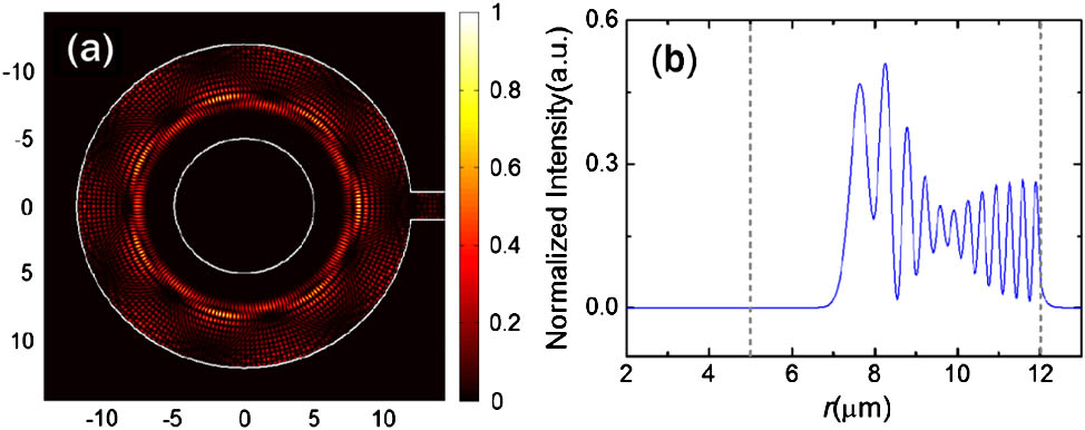
Figure 1.(a) Field distribution and (b) normalized radial intensity distribution for a high- coupled mode at 1553.2 nm in a microring resonator with a radius of 12 μm, an inner radius of 5 μm, and a 2 μm directly connected output waveguide.
The normalized radial intensity distribution in Fig. 1(b) is defined as where is the magnetic field for the TE mode. As shown in Fig. 1(b), the intensity distribution of the coupled mode has a radial width of about 5 μm. Considering the possible scattering loss caused by the rough inner surface, we fabricate a microring laser with an external radius of 12 μm and a ring width of 7 μm in this paper.
An AlGaInAs/InP laser wafer with the active region consisting of six compressively strained quantum wells is used for fabricating the microring lasers. An 800 nm layer is first deposited by plasma-enhanced chemical vapor deposition (PECVD) on the laser wafer. Then, the cavity patterns are transferred onto the layer using contacting photolithography and inductively coupled-plasma (ICP) etching techniques. The patterned layer is used as a hard mask to etch the AlGaInAs/InP laser wafer with the ICP etching process with a total etching depth of about 4.7 μm. Subsequently, bromine water is used to remove the reactants and smooth the side walls, and the residual hard masks are removed using HF solution. After that, a 200 nm silicon nitride () layer is deposited by PECVD on the wafer to get better adherence to the benzocyclobutene (BCB) layer, which is coated to create a planar surface. After coating the BCB layer, a curing process for the BCB layer is carried out in a atmosphere to avoid oxidation. The hard-cured BCB film is etched, by reactive ion etching (RIE) process, without any mask to expose the top of the ring-shaped resonators. Then, a 500 nm layer is deposited on the whole wafer, and the contact window is opened by ICP etching again for current injection on the top of each resonator. Finally, a Ti/Pt/Au p-electrode is deposited by e-beam evaporation and a lift-off process, then the laser wafer is mechanically lapped down to a thickness of 120 μm, and an Au–Ge–Ni metallization layer is used as an n-type electrode. The schematic diagram and the microscopic picture of a microring laser connected with an output waveguide are shown in Figs. 2(a) and 2(b). After cleaving over the output waveguide, the microring laser is bonded p-side up on an AlN submount with a thin-film resistance of 40 Ω in series to match the impedance to about 50 Ω for a high-speed modulation test, and mounted on a thermoelectric cooler (TEC).

Figure 2.(a) Schematic diagram of the microring laser connected with an output waveguide, and (b) a microscopic picture of a microring laser with a cleaved output waveguide.
3. CHARACTERISTICS OF A MICRORING LASER UNDER A FREE-RUNNING STATE
We first characterize a free-running microring laser with an external radius of 12 μm and a ring width of 7 μm connected to a 2 μm wide output waveguide. The output power coupled into a tapered multimode fiber (MMF) and the applied voltage are measured at TEC temperature of 290 K and plotted as functions of the continuous biasing current in Fig. 3(a). The threshold current is 10 mA, and the maximum output power is 108 μW at 29.5 mA. A series resistance of 22.5 Ω is estimated from the applied voltage versus the current around the threshold current. The lasing spectrum, measured by an optical spectrum analyzer (OSA) with resolution of 0.06 nm, is plotted in Fig. 3(b) for the microring laser with biasing current of 25 mA. Four main lasing peaks at 1547.8, 1557.1, 1566.7, and 1576.3 nm appear in the lasing spectrum, which can be attributed to the same transverse mode with longitudinal mode intervals of 9.3, 9.6, and 9.6 nm. Furthermore, we can observe six evident resonant modes over a longitudinal mode interval corresponding to different transverse modes. The lasing mode wavelength and the side-mode suppression ratio (SMSR) are 1557.1 nm and 33.4 dB at 290 K, respectively.
Figure 3.(a) Multimode fiber coupled power and the applied voltage versus continuous biasing current and (b) lasing spectrum at a continuous biasing current of 25 mA, for a 12 μm radius microring laser at TEC temperature of 290 K.
The small-signal modulation response is determined by measuring the parameter using a 20 GHz bandwidth network analyzer. Using a high-frequency bias-T, the biasing current, together with the modulation signal, is fed to the microring laser through a radio-frequency probe. The emitting light is coupled into a tapered single-mode fiber (SMF) and amplified by an erbium-doped fiber amplifier (EDFA) followed by an optical bandpass filter, to suppress the amplified spontaneous emission noise. The small-signal modulation responses measured at the TEC temperature of 290 K are plotted in Fig. 4 for the free-running microring laser at the biasing currents of 15, 18, 20 and 25 mA. The resonance peak heights are about 4.8, 5.8, 6.6 and 7.3 dB and the corresponding resonance frequencies are 4.8, 5.9, 6.5 and 7.5 GHz at 15, 18, 20 and 25 mA, respectively.
Figure 4.Small-signal modulation responses for the 12 μm radius microring laser at biasing currents of 15, 18, 20, and 25 mA and TEC temperature of 290 K.
4. DYNAMIC CHARACTERISTICS OF A MICRORING LASER SUBJECT TO OPTICAL INJECTION
In this section, the small-signal modulation responses are investigated for the microring laser subject to external optical injection from a tunable laser, using the experimental setup as shown in Fig. 5. A narrow-linewidth tunable laser is used for the optical injection through an optical circulator. The laser emissions, after amplified by the EDFA and filtered by the band-pass filter, are split into two parts by an optical fiber beam splitter with 1% of the output launched into an OSA and 99% of the output fed into a high speed photodetector with a 3 dB bandwidth of 32 GHz. The small-signal modulation response in Fig. 4 is measured using the same apparatus without optical injection from the tunable laser. As the practical power injected into the microcavity is hard to measure, we firstly measured the photocurrent under 0 V biasing voltage to estimate the injection coefficient. The detected photocurrent is around 40 μA at the injection optical power of 1 mW. We also measured the isolation ratio of the circulator used in the measurement system as the ratio of the input power to the output power for light injection in the reverse direction, which turns out to be .
Figure 5.Schematic diagram of the apparatus used for (a) the small-signal modulation response measurement and (b) the microwave signals generated by optical beam beating, for the microring laser subject to external optical injection.
Setting the output power of the tunable laser to 1 mW, we measure the small-signal modulation responses and lasing spectra for the microring laser subject to external optical injection with varying wavelength detuning , which is defined as the difference between injection light wavelength and the lasing mode wavelength , as . The lasing spectra and the small-signal modulation responses measured at biasing current of 25 mA and TEC temperature of 290 K are plotted in Fig. 6, under negative detuning , , , and for Figs. 6(a) and 6(b), and positive detuning , 0.120, 0.103, and 0.084 nm for Figs. 6(c) and 6(d). In addition to the lasing mode and the injection light, we observe an additional peak when the peak wavelength is varied from 1557.48 to 1557.44 nm, as shown in Fig. 6(a), corresponding to four-wave mixing at a wavelength of . Compared with the small-signal response curves for the free-running microring laser in Fig. 4, additional resonance peaks appear at 17.3, 16.4, 13.5, and 11.5 GHz for , , , and , respectively, corresponding to the beat frequency between the lasing mode and the injection light. The additional resonance peak height increases from 17.4 to 30.0 dB when the detuning value varies from to , and the height of the corresponding relaxation oscillation peak around 8.0 GHz decreases from 6.5 to 2.8 dB.
Figure 6.Lasing spectra and small-signal modulation responses for the microring laser under 1 mW optical injection at biasing current of 25 mA and TEC temperature of 290 K. The wavelength detuning values are , , , and for (a) and (b), and 0.149, 0.120, 0.103, and 0.084 nm for (c) and (d).
Similarly, additional peaks are also observed in Fig. 6(c) with the wavelength increasing from 1557.20 to 1557.26 nm, when decreases from 0.149 to 0.084 nm. Additional resonance peaks at the frequencies of 18.0, 15.0, 12.9, and 9.4 GHz are observed in the small-signal modulation response curves in Fig. 6(d), with peak values of 17.0, 22.2, 24.4, and 31.6 dB, respectively. The results indicated that similar small-signal modulation responses could be obtained for microring lasers under optical injection with positive and negative wavelength tunings.
The small-signal modulation response curves are also measured under a fixed injection wavelength and different injection powers of 0.4, 1, and 3 mW. The corresponding lasing spectra and small-signal modulation response curves are plotted in Figs. 7(a) and 7(b) for a negative detuning operation with , and in Figs. 7(c) and 7(d) for positive detuning operation with . As the optical injection power increases from 0.4 to 3 mW, the additional resonance peak increases from 18.0 to 26.1 dB with corresponding peak frequency increases from 15.7 to 17.3 GHz, as shown in Fig. 7(b). This is caused by the redshift of the lasing mode wavelength due to carrier density reduction with increase of the injection optical power, thus leading to increase of the actual wavelength detuning for the negative detuning situation. In contrast, for positive wavelength detuning, as shown in Fig. 7(d), the additional resonance peak increases from 10.6 to 27.2 dB with peak frequency decreases from 17.4 to 15.3 GHz, as the injection optical power increases from 0.4 to 3 mW.
Figure 7.Lasing spectra and small-signal modulation responses for a microring laser under optical injection at the wavelength 1557.2 nm and optical powers of 0.4, 1, and 3 mW, for the microring laser at biasing current of 25 mA and TEC temperature of 290 K. (a) and (b) correspond to negative detuning operation with , while (c) and (d) correspond to positive detuning operation with .
The measured additional resonance peak frequency is summarized in Fig. 8(a), shown as squares, circles, and triangles for injection optical powers of 0.4, 1, and 3 mW, respectively. It changes nearly linearly with frequency detuning and is less affected by the injection power. The heights of the additional resonance peaks versus the detuning wavelengths are also plotted for injection optical powers of 0.4, 1, and 3 mW in Fig. 8(b). The results indicate that the resonance peak frequency can be tuned by changing the detuning frequency of the injection light while the resonance heights can be adjusted by changing both the detuning frequency and the injection optical power.
Figure 8.(a) Additional resonance peak frequencies and (b) the heights of resonance peaks versus detuning wavelength for a microring laser at injection powers of 0.4, 1, and 3 mW, under continuous biasing current of 25 mA and TEC temperature of 290 K.
5. MICROWAVE SIGNALS GENERATED BY LIGHT BEATING
Figure 9.Microwave signals of the beat signal between the lasing mode and 1 mW injection optical wave for the cases with (a) the positive and (b) the negative detuning wavelengths, respectively, for the microring laser under the continuous biasing current of 25 mA and TEC temperature of 290 K.
Finally, the microwave signals generated by the light beating between the lasing mode and the injection light are investigated by the apparatus in Fig. 5(b), utilizing a spectrum analyzer with a bandwidth of 26.5 GHz and a high-speed photodetector. The generated microwave signals at injection optical power of 1 mW are plotted in Figs. 9(a) and 9(a), under positive and the negative wavelength detuning , respectively, for a microring laser at continuous current of 25 mA and TEC temperature of 290 K. With the increase of , the magnitudes of the microwave signal are gradually reduced from at 11.2 GHz to at 21.5 GHz in Fig. 9(a) for positive detuning. The second peak at 22.4 GHz, which is double the main peak frequency of 11.2 GHz, is observed with magnitude of . For negative wavelength detuning, the magnitudes of the microwave signal are reduced from at 9.9 GHz to at 19.1 GHz, as shown in Fig. 9(b), and a second peak at 19.8 GHz with magnitude of is observed. The small second peaks can be attributed to the light beating signal between the injection light and the four-wave mixing light, as shown in Figs. 6(a) and 6(c).
However, if the tunable laser output is combined only with that of a microring laser using a lightwave combiner rather than injected into the microring laser, we can observe small-signal modulation curves without the additional peak, similar as those measured under the free-running state in Fig. 4. The results indicate that the additional resonance peak observed around the detuning frequency should be related to the interaction between carriers and photons inside the microcavity. Unlike the optical injection locking state, which improves the modulation response by changing the lasing frequency [15–18], the four-wave mixing state seems to have less impact on the intrinsic resonance frequency of the microring laser. Theoretical analysis based on multimode rate equation will be more complicated and require further investigation for the four-wave mixing state.
6. CONCLUSIONS
In summary, we have investigated small-signal modulation response and microwave generation based on light wave beating, for a microring laser with radius of 12 μm subject to optical injection. Single-mode operation with a SMSR of 33.4 dB is obtained for the microring at TEC temperature of 290 K and continuous current of 25 mA, and a corresponding 3 dB bandwidth of 12.4 GHz is obtained for the free-running microring laser. An additional resonance peak induced by four-wave mixing is observed in the small-signal modulation response curve for the microring laser subject to external optical injection from a tunable laser. In addition, optical generation of a microwave signal is realized based on light beating between the injection light and the lasing mode of the microring laser. The demonstration of enhanced modulation response as well as the optical generation of microwave signal based on optical injection operation will bring more application prospects for the microring lasers in the future photonics integrated circuit.
References
[1] S. L. McCall, A. F. J. Levi, R. E. Slusher, S. J. Pearton, R. A. Logan. Whispering-gallery mode microdisk lasers. Appl. Phys. Lett., 60, 289-291(1992).
[2] T. Baba, M. Fujita, A. Sakai, M. Kihara, R. Watanabe. Lasing characteristics of GaInAsP-InP strained quantum-well microdisk injection lasers with diameter of 2-10 μm. IEEE Photon. Technol. Lett., 9, 878-880(1997).
[3] L. He, Ş. K. Özdemir, L. Yang. Whispering gallery microcavity lasers. Laser Photon. Rev., 7, 60-82(2013).
[4] S. J. Choi, K. Djordjev, S. J. Choi, P. D. Dapkus. Microdisk lasers vertically coupled to output waveguides. IEEE Photon. Technol. Lett., 15, 1330-1332(2003).
[5] M. J. R. Heck, H. W. Chen, A. W. Fang, B. R. Koch, D. Liang, H. Park, M. N. Sysak, J. E. Bowers. Hybrid silicon photonics for optical interconnects. IEEE J. Sel. Top. Quantum Electron., 17, 333-346(2011).
[6] P. Mechet, T. Spuesens, S. Werquin, K. Vandoorne, N. Olivier, J.-M. Fedeli, P. Regreny, D. Van Thourhout, G. Roelkens, G. Morthier. All-optical low-power 2R regeneration of 10-Gb/s NRZ signals using a III-V on SOI microdisk laser. IEEE Photon. J., 5, 7802510(2013).
[7] J. Van Campenhout, P. Rojo-Romeo, P. Regreny, C. Seassal, D. Van Thourhout, S. Verstuyft, L. Di Cioccio, J. M. Fedeli, C. Lagahe, R. Baets. Electrically pumped InP-based microdisk lasers integrated with a nanophotonic silicon-on-insulator waveguide circuit. Opt. Express, 15, 6744-6749(2007).
[8] S. J. Wang, J. D. Lin, Y. Z. Huang, Y. D. Yang, K. J. Che, J. L. Xiao, Y. Du, Z. C. Fan. AlGaInAs-InP microcylinder lasers connected with an output waveguide. IEEE Photon. Technol. Lett., 22, 1349-1351(2010).
[9] X. M. Lv, L. X. Zou, J. D. Lin, Y. Z. Huang, Y. D. Yang, Q. F. Yao, J. L. Xiao, Y. Du. Unidirectional-emission single-mode AlGaInAs-InP microcylinder lasers. IEEE Photon. Technol. Lett., 24, 963-965(2012).
[10] Y. D. Yang, S. J. Wang, Y. Z. Huang. Investigation of mode coupling in a microdisk resonator for realizing directional emission. Opt. Express, 17, 23010-23015(2009).
[11] X. M. Lv, L. X. Zou, Y. Z. Huang, Y. D. Yang, J. L. Xiao, Q. F. Yao, J. D. Lin. Influence of mode Q factor and absorption loss on dynamical characteristics for semiconductor microcavity lasers by rate equation analysis. IEEE J. Quantum Electron., 47, 1519-1525(2011).
[12] X. M. Lv, Y. Z. Huang, L. X. Zou, H. Long, Y. Du. Optimization of direct modulation rate for circular microlasers by adjusting mode Q factor. Laser Photon. Rev., 7, 818-829(2013).
[13] X.-M. Lv, Y.-Z. Huang, L.-X. Zou, H. Long, J.-L. Xiao, Y.-D. Yang, Y. Du. High-speed direct modulation unidirectional emission microring lasers. Electron. Lett., 49, 1290-1291(2013).
[14] X.-M. Lv, Y.-Z. Huang, Y.-D. Yang, L.-X. Zou, H. Long, B.-W. Liu, J.-L. Xiao, Y. Du. Influences of carrier diffusion and radial mode field pattern on high speed characteristics for microring lasers. Appl. Phys. Lett., 104, 161101(2014).
[15] E. K. Lau, L. H. Wong, M. C. Wu. Enhanced modulation characteristics of optical injection-locked lasers: a tutorial. IEEE J. Sel. Top. Quantum Electron., 15, 618-633(2009).
[16] C. H. Chen, K. Takeda, A. Shinya, K. Nozaki, T. Sato, Y. Kawaguchi, M. Notomi, S. Matsuo. 40-Gb/s directly-modulated photonic crystal lasers under optical injection-locking. Opt. Express, 19, 17669-17676(2011).
[17] S. Lee, D. Parekh, T. Shindo, W. J. Yang, P. Guo, D. Takahashi, N. Nishiyama, C. J. Chang-Hasnain, S. Arai. Bandwidth enhancement of injection-locked distributed reflector lasers with wirelike active regions. Opt. Express, 18, 16370-16378(2010).
[18] N. Zhang, X. Cai, S. Yu. Optical generation of tunable and narrow linewidth radio frequency signal based on mutual locking between integrated semiconductor lasers. Photon. Res., 2, B11-B17(2014).
[19] G. J. Schneider, J. A. Murakowski, C. A. Schuetz, S. Y. Shi, D. W. Prather. Radiofrequency signal-generation system with over seven octaves of continuous tuning. Nat. Photonics, 7, 118-122(2013).
[20] M. I. Memon, G. Mezosi, B. Li, D. Lu, Z. Wang, M. Sorel, S. Yu. Generation and modulation of tunable mm-wave optical signals using semiconductor ring laser. IEEE Photon. Technol. Lett., 21, 733-735(2009).
[21] B. Li, M. I. Memon, G. Mezosi, G. Yuan, Z. Wang, M. Sorel, S. Yu. All-optical response of semiconductor ring laser to dual-optical injections. IEEE Photon. Technol. Lett., 20, 770-772(2008).
[22] X. W. Ma, X. M. Lv, Y. Z. Huang, Y. D. Yang, J. L. Xiao, Y. Du. Mode characteristics for unidirectional emission microring resonator lasers. J. Opt. Soc. Am. B, 31, 2773-2778(2014).


