
Lihan Wang, Lingyun Ren, Xiangchuan Wang, Shilong Pan. Time-resolution enhanced multi-path OTD measurement using an adaptive filter based incoherent OFDR[J]. Chinese Optics Letters, 2024, 22(1): 013901
- Chinese Optics Letters
- Vol. 22, Issue 1, 013901 (2024)
Abstract
Keywords
1. Introduction
Multi-path and high-accuracy optical transfer delay (OTD) measurement is fundamental to many applications, including distributed and quasi-distributed optical sensing[1], distributed coherent aperture radars[2,3], and optical true-time-delay-based phase arrays[4,5]. Commonly applied multi-path OTD measurements are realized based on time-multiplexed[6–8] and frequency-multiplexed[9–17] techniques. Time-multiplexed measurement systems, taking optical time-domain reflectometry (OTDR) as an example, can achieve long-range OTD measurement. However, the resolution of OTDR is usually on the nanosecond level, limited by the pulse width and the receiver’s bandwidth. Frequency-multiplexed OTD measurement techniques can provide high resolution, which can be classified into coherent systems[9] and incoherent systems[10]. Optical frequency domain reflectometry (OFDR) is one representative coherent technique in which the OTD is transformed into the beat frequency of the probe light and the local oscillator (LO) light, providing high accuracy in short-range measurements. Nonetheless, it encounters limitations in enlarging the measurement range because of the nonlinearity in the time-frequency relationship of the optical signals and the coherent noise between the LO light and the probe light. Another coherent frequency-multiplexed technique for OTD measurement is established based on optical frequency combs[11,12], where the measurement range is restricted in most waveguides because of the dispersion effect. Additionally, the optical comb should be frequency locked, which complicates the measurement system.
Compared with coherent techniques, incoherent OFDR (I-OFDR) offers several unique features for OTD measurement. For example, it is immune to the effect of coherent optical noise, it is insensitive to polarization fading, and it has a high signal-to-noise ratio (SNR) because it uses narrowband receivers. Furthermore, the I-OFDR system has also been demonstrated to be insensitive to the multi-modal effect[13]. By sweeping the frequency of a microwave signal modulated on a low-coherence optical carrier, the radio frequency (RF) transfer function of an optical link under test can be obtained in the electrical domain. Then, the estimated time-domain response is given by the inverse discrete Fourier transform (iDFT). Benefitting from the fine and stable frequency scanning of the microwave source, these methods generally have a high accuracy (sub-picosecond level)[15]. Previously, researchers developed various algorithms to optimize the I-OFDR system’s performance[14–18], such as accuracy and speed. However, the time resolution of the I-OFDR is limited by the reciprocal of the bandwidth[16], which can be hardly improved by other methods. In addition, when the bandwidth is increased beyond a specific range, the measurement accuracy and resolution would not be further enhanced because the radio-over-fiber link suffers from severe dispersion distortion[19,20]. Moreover, a large frequency sweeping range would cost a lot of time and demand the use of broadband optoelectronic devices.
In this Letter, a novel resolution-enhancement method for I-OFDR is proposed. We construct a cost function based on the weighted least square (WLS) criterion to design an adaptive filter to suppress the spectral leakage from each path. The minimization of the cost function is then calculated iteratively to improve the time resolution of the OTD measurement, which breaks through the limitation of the bandwidth.
Sign up for Chinese Optics Letters TOC. Get the latest issue of Chinese Optics Letters delivered right to you!Sign up now
2. Principle
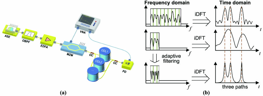
The schematic diagram of the I-OFDR system is illustrated in Fig. 1(a). A low-coherence optical carrier generated from an amplified spontaneous emission (ASE) source is modulated by an RF signal with a frequency of . After the intensity modulation, the optical signal transmits through the optical links under test. Each measured path has a different amplitude and phase response in the frequency domain. Then, the optical signal is transformed into a photocurrent in a photodetector (PD). The magnitude-phase difference between the photocurrent and the reference RF signal is extracted by a vector network analyzer (VNA), which can be written as
![]()
Figure 1.(a) Configuration of the I-OFDR system. ASE, amplified spontaneous emission source; OBPF, optical bandpass filter; EDFA, erbium-doped fiber amplifier; MZM, Mach–Zehnder modulator; OC, optical coupler; VNA, vector network analyzer; PD, photodetector; ODL, optical delay line. (b) Comparison of the estimated time-domain response between the iDFT-based methods and the adaptive filtering method.
For simplicity, we can rewrite Eq. (1) in matrix forms. Assuming that the number of the discrete frequencies of the sweeping RF signal is , the photocurrent vector can be expressed as
Equation (2) can be regarded as a DFT-like operation that maps the time-domain response to the frequency-domain response . The -point iDFT result of can be written as
For a given OTD to be measured, the interference from other measured paths and noise represented by the covariance matrix can be expressed as
The minimum value of the cost function corresponds to the optimal estimation result of , which can be given by
From Eq. (7), we can give the resolution-enhanced result of the estimated time-domain response , whose element is calculated from the iDFT of the filtered frequency response . Here, is the required filter to suppress the spectral leakage. Figure 1(b) illustrates the comparison of the estimated time-domain response between the iDFT-based methods and the adaptive filtering method. In the traditional iDFT-based method, the measured path may exhibit a large main lobe width in the time domain, especially when the frequency range of the sweeping RF is limited [see the second line in Fig. 1(b)]. Thanks to our proposed adaptive filtering method, the main lobe is significantly narrowed, leading to an enhanced measurement resolution [see the third line in Fig. 1(b)]. However, the precise parameter of the filter cannot be obtained in practical measurement. Here, we apply an iteration approach to solve this problem. The initial is set as an identity matrix. Then, the iteration process can be described as repeating Eqs. (8)–(10):
The stopping criterion of the iterative process can be set as , where is a preset threshold. To avoid the situation where the matrix is close to a singular value, we apply the Moore–Penrose pseudoinverse to replace the matrix inversion in the calculation. During the iteration, the filter adaptively finds the multi-path OTD. When the final iteration is over, we can obtain the estimated time-domain response, where directly reflects the amplitude response of the . Moreover, it should be noted that the WLS criterion is not the only criterion for this algorithm. Other criteria, such as the minimum mean square error (MMSE)[21] criterion, may also be appropriate for establishing the cost function if it has analytical expression.
| 1: Compute |
| 2: |
| 3: |
| 4: Compute |
| 5: Compute |
| 6: |
| 7: |
| 8: |
| 9: Compute |
| 10: Compute |
| 11: Compute |
| 12: |
Table 1. Muti-Path OTD Measurement Using Adaptive Filtering
3. Experiments and Discussion
A proof-of-concept experiment with the setup shown in Fig. 1(a) for measuring two optical fiber links is performed to validate the feasibility of the proposed adaptive filtering. A broadband optical signal from an amplfied spontaneous emission (ASE) source is filtered by an optical bandpass filter (OBPF) and then amplified by an erbium-doped fiber amplifier (EDFA). The optical signal is injected into a 40-GHz Mach–Zehnder modulator (MZM, IXblue MXAN-LN-40). The driven signal to the modulator is from a vector network analysis (R&S ZVA67). After small signal modulation, the optical signal transmits through the optical links under test. Then, the combined optical signal from the two optical fiber links is received by the vector network analysis (VNA) after being converted into an electrical current in a 40-GHz PD (Finisar XPDV2120R). The frequency of the VNA is swept from 200 MHz to 600 MHz with a sweeping step of 40 MHz. These settings correspond to a measurement range of 25 ns (i.e., 1/40 MHz) and a theoretical time resolution of 2.5 ns (i.e., 1/400 MHz).
In the experiment, the optical lengths of the two optical fiber links are separately controlled by two variable optical delay lines (ODLs, General Photonics MDL-002) with an accuracy of . The length difference between the two ODLs is set to 905 ps. The OTD range vector is set from 0 ns to 25 ns with an interval of 0.1 ps. By applying the proposed method, the iteration results of the location vector versus the OTD range vector are given in Figs. 2(a) and 2(b). The blue line in Fig. 2(a) shows the original iDFT result of the electrical current vector . Since the theoretical time resolution is only 2.5 ns, the iDFT algorithm results in spectral aliasing in the time domain. During the iteration, the OTDs of the two paths gradually converge to 8.1701 ns and 9.0748 ns. The detailed process is presented in Fig. 2(b), where the change of the estimated time-domain response with different iterations is shown as a heat map. The data of the iteration are given in Fig. 3(a). The path having the relatively weak amplitude response does not appear in until the third iteration. The relationship between and the iteration number is shown in Fig. 3(b). The value of declines exponentially with the iteration number. Because the OTDs of the two paths are converged to fixed values after 20 iterations, the threshold is set as 0.1 in the experiment. The choice of the threshold should consider the practice requirement. In some specific cases, such as a link with large loss being covered by other links, the threshold should be set small enough to recover the entire time-domain response. In addition, we can directly choose to stop the algorithm after a fixed number of iterations.
![]()
Figure 2.(a) Estimated time-domain response by applying the adaptive filter in different iterations. The blue line is the estimated response by using the iDFT algorithm. (b) Heat map of the estimated time-domain response in different iterations.
![]()
Figure 3.(a) Estimated OTDs of the two measurement paths as a function of the iteration number. (b) ‖Pnew−P‖2 versus the iteration number.
To evaluate the accuracy of the super-resolution OTD measurement method, ODL1 is changed from 100 ps to 0 ps with an interval of 10 ps while the other one is fixed. The measurement result is given in Fig. 4. The zoom-in views of the peaks representing the swept ODL1 and the fixed ODL2 are also shown. The deviation of the swept ODL1 and the measured OTD of the fixed ODL2 are presented in Figs. 5(a) and 5(b), respectively. From the results, the error of the OTD measurement system is less than .
![]()
Figure 4.The estimated time-domain response under the test of ODL1 and ODL2 when the delay of ODL1 changes from 100 ps to 0 ps with a step of 10 ps.
![]()
Figure 5.Evaluation of the system’s accuracy when ODL1 changes from 100 ps to 0 ps. (a) The deviation of ODL1 in measurement. (b) The measured OTD of ODL2.
The measurement error of the system versus the signal-interference ratio is also analyzed by a numerical simulation. The frequency is swept from 1 GHz to 9 GHz (corresponding to a measurement resolution of 125 ps) with an interval of 0.5 GHz when the two optical paths are set at 570.4 ps and 630.7 ps. The simulation results, which are repeated 100 times by Monte Carlo simulation, are given in Fig. 6. Figure 6(a) compares the total variance with the signal-interference ratio (i.e., ), which fits well with the linear relationship. The total error versus the signal-interference ratio also presents a linear relationship, as Fig. 6(b) shows. Improving the signal-interference ratio can lead to enhanced accuracy and precision simultaneously. When the signal-interference ratio is worse than 20 dB, we cannot achieve an effective time-domain response by the proposed method. This may be caused by the choice of initial . The error components can be accumulated in the iteration. As is illusatrated in Fig. 6(b), to achieve a measurement error of less than 1 ps, the signal-interference ratio should be better than 40 dB.
![]()
Figure 6.Monte Carlo simulation results of two measurement channels with 570.4 ps and 630.7 ps when the frequency range is 8 GHz. (a) The total variance as a function of the signal-interference ratio. (b) The total error as a function of the signal-interference ratio.
4. Conclusion
In conclusion, we propose an I-OFDR-based multi-path OTD measurement method with enhanced time resolution by designing an adaptive filter to filter the spectral leakage induced by the iDFT. The time resolution is improved to exceed 900 ps when the traditionally defined resolution limit is 2.5 ns. In addition, an OTD measurement precision of is achieved. The influence of the signal-interference ratio is also investigated through Monte Carlo simulation. By using a high-performance magnitude-phase receiver to improve the signal-interference ratio, the measurement accuracy can be further improved. In conclusion, the proposed adaptive filtering method, featuring improved time resolution, holds promising prospects in distributed optical sensing and multi-path optical delay measurement.

Set citation alerts for the article
Please enter your email address
© Copyright 2018-2021 | Chinese Laser Press. All Rights Reserved 沪ICP备15018463号-20