Ruqi Zhang, Jianfeng Li, Zhitong Huang, Yuefeng Ji, "Adaptive frequency domain pre-equalization for white-LED nonlinearity in OFDM-based visible light communication systems," Chin. Opt. Lett. 13, 072302 (2015)
Copy Citation Text
In visible light communication, orthogonal frequency division multiplexing (OFDM) is an effective approach to improve the system speed. However, the nonlinearity of the light-emitting diode (LED) suppresses the transmission performance. The low-frequency part of the transmitted signal from LED suffers more from nonlinearity. Therefore, a pre-equalization scheme which suppresses the low frequency part of the OFDM signal and enhances the high frequency part can decrease the impact of LED nonlinearity. The experimental results show that the bit-error rate performance is largely enhanced by the pre-compensation.
Recently, white-light-emitting diodes (LEDs) have been recommended to be future lighting devices, which have a lot of desired properties such as high efficiency, long lifetime, small size, and low heat generation. Visible light communication (VLC) based on LEDs has been researched extensively as next-generation indoor high-rate data communication[1–7]. Current research in VLC is mainly focus on how to improve the system transmission rate. Discrete power level stepping scheme in the transmitter[8], parallel data transmission[9], utilization of novel materials (gallium nitride μLED)[10], and the hybrid equalization technique[11] have improved the VLC system transmission data rate and bit-error rate (BER) performance in different styles. Several kinds of orthogonal frequency division multiplexing (OFDM) technologies were proposed to improve the VLC data transmission rate. However, the impact of LED nonlinearity on an OFDM-based VLC system cannot be neglected and it is a necessary element restraining the OFDM system transmission capacity and performance[12]. In OFDM systems, linear distortions such as attenuation and inter-symbol interference (ISI) can be compensated with amplifiers and equalizers. However, nonlinear distortions which cause interferences both inside and outside the signal bandwidth (called nonlinearity crosstalk noise) generate irreversible changes for the OFDM symbols. Elgala et al.[13] proposed a model which incorporates OFDM signal conditioning to the characteristics of the LED. Concerning the nonlinear behavior of LED, Neokosmidis et al.[14] highlights its influence on subcarriers in the low-frequency range of the OFDM system but without taking into account the LED dynamic nonlinear behavior. Some LED nonlinearity mitigation techniques (decision feedback equalization and multiple LEDs) for OFDM systems have been presented[15–18]. The mentioned technique[17] requires another LED source to reduce the distortion of OFDM symbols, which is not suitable for single LED communication. A kind of analog pre-equalization (resistance inductance capacitance circuit pre-equalization) scheme[19] was proposed, and the pre-equalization was not suitable for OFDM-based VLC system. In this work, we deeply study the pre-equalization effect of the LED nonlinearity. Chow et al.[20] proposed a time domain equalization method to improve the VLC transmission capacity; however, the frequency domain equalization is easy to complete by the changing the subcarriers’ power. In this work, we adopt the simply implemented method.
In this work, an adaptive pre-equalization scheme in frequency domain is designed and demonstrated experimentally to cope with the LED nonlinearity for OFDM-based VLC systems. A commercially available white-LED with 3 dB bandwidth of 15 MHz is used. With the help of pilot symbols for channel estimation, the adaptive pre-equalization suppresses the low frequency part of the OFDM signal to mitigate the system nonlinearity. The experimental results show that improved performance at a distance of 0.5 m is achieved and the BER performance can be enhanced significantly with 64-quadrature amplitude modulation (QAM)–OFDM.
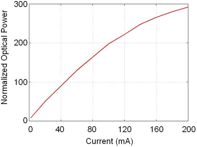
In a VLC system, the main source of nonlinearity is the LED. Because of the self-heating characteristic, the LED conversion efficiency of electrical-to-optical (E/O) drops. Hence, the LED output light power is nonlinear with the drive current as the LED is overheating.
Sign up for Chinese Optics Letters TOC. Get the latest issue of Chinese Optics Letters delivered right to you!Sign up now
In Fig. 1, the E/O characteristic of a commercially available white-LED (OSTAR SL2N) is measured with different bias currents and strong nonlinearity is observed. Figure 2 shows the estimated SNR, the blue line shows the LED channel response (SNR versus frequency), and the green line depicts the frequency domain channel pre-compensation. The 3 dB bandwidth of the LED channel achieves 15 MHz.
Figure 1.Measured optical power against LED current.
To confirm the nonlinear phenomenon still further, the power spectra of the sinusoidal signal with 12.5 dBm are shown in Fig. 3. The red lines denote the power spectra of the driving signal, and the blue lines show the power spectrums of the optical signal from the LED. With the driving signal of 10 MHz, the second- and the third-order term harmonics are generated at the level of and . Increasing the frequency to 50 MHz, we can see that the intensity of second-order harmonics decreases to . Note that the low-frequency part of the signal from the LED suffers more from the nonlinearity. Therefore, we can try to suppress the power of the low-frequency part of the signal to decrease the LED nonlinearity.
Figure 3.Measured output power spectrum: (a) 10 and (b) 50 MHz (sinusoidal signal of 1.1 V at the bias current of 100 mA).
The block diagram of the adaptive pre-equalization for the OFDM system is presented in Fig. 4. The input binary bit streams are encoded into -ary QAM symbols. The pilots are inserted for channel response estimation, and the pre-equalization is operated. Then Hermitian symmetry of complex signals is used before inverse fast Fourier transform (IFFT) input to produce a real time domain output signal. The cycle prefix (CP) is inserted to avoid ISI. At the receiver, the pilots are extracted and fed back to the transmitter. Least-squares (LS) estimation at pilot tones and linear interpolation are utilized to estimate the channel response. After the pre-compensation, the amplitudes of subcarriers in the frequency domain can be expressed as where is amplitude response of channel estimation and is the amplitude of subcarrier in frequency domain. Both and are complex quantities. is always similar to an exponential decay. Consequently, the pre-equalization not only suppresses the low-frequency part of the OFDM signal, but also enhances the high-frequency part. The LED nonlinearity could be mitigated for the OFDM systems.
Figure 4.Schematic of adaptive pre-compensation for our OFDM system. AMP, amplifier; LPF, low-pass filter; P/S, parallel to serial; S/P, serial to parallel.
The experimental setup is shown in Fig. 5. In the transmitter, the output signal of the arbitrary waveform generator (AWG; Tektronix, AWG5012, 1 GS/s) is amplified by means of a power amplifier (PA; Mini-Circuits 20 dB gain), superimposed on a direct current (DC; 110 mA) bias and used to drive the LED, a lens (Thorlabs, ACL2520-DG6, diameter 25 mm, focal distance 20 mm, refractive index 1.474) is used to focus the visible light. At the receiver side (Rx), a lens (Thorlabs, 30 mm diameter) with blue filter (400–480 nm) is used to collect the light onto a photodiode (PD; Thorlabs, PDA10A; DC, 150 MHz) module having active area. The received signal is recorded by a real-time oscilloscope (OSC; LeCroy735Zi, 1 GS/s). The signal processing (SNR evaluation, OFDM sequence generation, and BER analysis) is performed off-line by Matlab (educational software).
The measured power spectra of OFDM symbols are shown in Fig. 6. Figures 6(a) and 6(c) are the power spectrums of driving signal from the PA. Figures 6(b) and 6(d) are the power spectrums of the received optical signal from the PD. It can be easily seen that after the pre-equalization the low-frequency parts of the OFDM subcarriers are suppressed while the high-frequency parts are enhanced in the frequency domain. In this work, the sampling speed of the digital to analog converter and analog to digital converter is , the fast Fourier transformation (FFT) size is , and the subcarriers interval is: , when , , and the is constant (0.488 MHz). The bandwidth is shown as , when the subcarriers number is , and ; further increasing , the will reach the PD bandwidth (150 MHz). Each OFDM symbol consists of subcarriers (including 18 pilots) within a bandwidth of . To avoid the inflection point (4 MHz) in the electronic photonic electronic channel response, the OFDM subcarriers starting from 5.8 to 146.4 MHz is shown in Fig. 7. By increasing the number of subcarriers, the bandwidth of OFDM exceeds the detection range (150 MHz) of the PD that we use. In this work, the number of 288 subcarriers is a good compromise. The total transmission length of the sequence is 1000 OFDM symbols in our work.
Figure 6.Measured power spectrums of OFDM symbols: (a) without pre-equalization (driving signal from PA); (b) without pre-equalization (received signal from PD); (c) with pre-equalization (driving signal from PA); (d) with pre-equalization (received signal from PD).
First we try to find a proper LED bias current. In this work, the modulation format of 64-QAM is used, and the driving signal of OFDM is fixed at 11.5 dBm (signal power). The experimental result is presented in Fig. 8, where the constellations are also shown. The constellations are obtained by the following way. The OFDM symbols are sent by the LED, and transmitted in the free space, in the receiver, we demodulated the OFDM symbol and obtained the constellations (288 subcarriers × 1000 symbols). The distance between the transmitter and the receiver is 0.5 m. We can obtain an optimal bias current of 110 mA. By further increasing the bias current, the signal magnitudes exceed the maximum linear interval, and the system BER starts to increase.
Figure 8.BER versus the OFDM signal power with 32-QAM.
The measured BER performances versus the OFDM signal power are shown in Figs. 8 and 9. Starting at 5 dBm, the BER performances are improved by increasing the signal power. It can be observed that there is an optimal OFDM signal mean power, which is determined by the characteristics of LED nonlinearity. Further increasing the OFDM signal power the BER performances begin to get worse. When the OFDM signal power is changing from 5 to12 dBm, the LED works in the linear range, further increasing the OFDM signal power (PA) (12–25 dBm), it will exceed the LED linear range, so we can see the nonlinear characteristic.
Figure 9.BER versus the OFDM signal power with 64-QAM.
It is worth noting that the noise dominates at low power of the OFDM symbols while the nonlinearity dominates at a high power of symbols for the overall system performance. Figure 8 shows the BER performances of 32-QAM at the gross bit rate of 703 Mb/s. The black line denotes the BER without pre-equalization (wo-pre) while the green line shows the performance with pre-equalization (pre). The BER with pre-equalization can decrease to level compared with that without pre-compensation (). Figure 9 depicts the BER of gross bit rate 844 Mb/s with 64-QAM. The BER performances of level can be obtained compared with that without pre-equalization ().
In conclusion, we design and experimentally demonstrate an adaptive frequency domain pre-equalization for OFDM-based VLC systems. In a VLC system, the LED channel response is always similar to an exponential decay, thus the low frequency part of the OFDM signal suffers more from the nonlinearity. With the help of channel estimation, the pre-equalization is operated before IFFT to suppress the low-frequency parts of the OFDM subcarriers, which is the main nonlinearity source. With 32-QAM–OFDM and 64-QAM–OFDM, the gross bit rate all achieved improved performance. The experimental transmission data rate is confined by the PD used in this work (150 MHz) while a higher transmission data rate can be achieved by a PD with higher bandwidth.
References
[1] J. Vucic, C. Kottke, S. Nerreter, K. D. Langer, J. W. Walewski. J. Lightwave Technol., 28, 3512(2010).
Ruqi Zhang, Jianfeng Li, Zhitong Huang, Yuefeng Ji, "Adaptive frequency domain pre-equalization for white-LED nonlinearity in OFDM-based visible light communication systems," Chin. Opt. Lett. 13, 072302 (2015)