
Dewen Cheng, Hailong Chen, Tong Yang, Jun Ke, Yang Li, Yongtian Wang, "Optical design of a compact and high-transmittance compressive sensing imaging system enabled by freeform optics," Chin. Opt. Lett. 19, 112202 (2021)
- Chinese Optics Letters
- Vol. 19, Issue 11, 112202 (2021)
Abstract
1. Introduction
Computational imaging can be seen as indirectly forming images from measurements using algorithms that rely on a significant amount of computing[
Freeform optical surfaces can be characterized as non-rotationally symmetric surfaces, and they can offer many more degrees of freedom for imaging system design. They can correct the aberrations well in non-symmetric systems and help to achieve better imaging performance, higher system specifications, more compact system configuration, and fewer elements. Using freeform optical surfaces in imaging systems can be seen as a revolution in the field of optical design[
In this Letter, we demonstrate a design of a CS imager using freeform optics. This is the first time, to the best of our knowledge, that freeform surfaces are introduced in the design of computational imaging and CS systems. The entire system works under the medium wave IR band (MIR). A novel system configuration is proposed. An off-axis freeform three-mirror objective system and coaxial relay optics are integrated to realize CS. The design method and strategy of a freeform CS imaging system are proposed. The design and integration process of the individual parts, as well as the joint design of the entire CS system, are demonstrated, including pupil matching, light obscuration elimination, system structure control, and system specifications control. The final system realizes a 16 times compression and an FOV of
Sign up for Chinese Optics Letters TOC. Get the latest issue of Chinese Optics Letters delivered right to you!Sign up now
2. Basic Principles and System Specifications
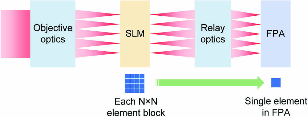
The basic principles of CS used for the IR systems in this Letter are summarized as follows[
![]()
Figure 1.Sketch of the MIR CS system.
In this Letter, a digital micromirror device (DMD) is taken as the SLM. The DMD used in the system has
![]()
Figure 2.FOV coverage of the system. (a) Rectangular FOV. (b) The FOV coverage is rotated. (c) The FOV coverage used in the actual design process.
3. System Design Using Traditional Spherical Lenses
We first discuss the design using traditional imaging optics. In Ref. [4], the authors have presented a good design (the system specifications are different from those of this Letter). Both the objective optics and the relay optics use traditional spherical lenses (11 IR lenses are used in total). Here, we present a similar design for the requirements given in this Letter, as shown in Fig. 3. Nine IR lenses are used in total. The coaxial objective optics consist of three IR spherical lenses. Light coming from the object space is focused on the DMD plane (a ZnSe window is located above the DMD plane), which is the intermediate image plane of the entire system. In the “on” state, the DMD mirrors are tilted at 12°. The light will be reflected by 24° and travel back through objective lenses. Then, the light will be deflected into the relay optics, which consist of six spherical lenses, and finally will be focused on the FPA and form the image. In the “off” state, the DMD mirrors are tilted at
![]()
Figure 3.Layout of the system using traditional spherical lenses.
![]()
Figure 4.MTF plots of the traditional design. (a) Entire system. (b) Objective optics.
4. System Design Using Freeform Optics
To overcome the drawbacks of the traditional design, in this Letter, we represent an alternative design with the same system specifications, which use freeform surfaces in the system. The objective optics and the relay optics are firstly designed separately and then are integrated as one system for final joint optimization. The detailed design processes are depicted as follows.
As the design requires high imaging performance over the full FOV in both the objective optics and the final entire system, and strict requirements in system configuration should be fulfilled (such as large chief ray angle on DMD, and elimination of light obscuration), all three mirrors are freeform surfaces, and the surface type is an XY polynomials surface up to the sixth order with a base conic at this design stage. Because the optical system is symmetric about the YOZ plane, only the even items of
![]()
Figure 5.Design result of the freeform objective system. (a) System layout. (b) MTF plot.
The relay optics are used to reimage the scene from the DMD to the FPA. Here, a rotationally symmetric coaxial system is designed. The relay optics consist of four spherical lenses. The exit pupil of the system should match the cold stop of the cooled detector. In this way, the cold stop can be used with high efficiency in order to significantly limit the unwanted background radiation and increase the signal-to-noise ratio. In this design, the cold stop is set as the aperture stop of the system directly. The field type used in the design is object height. The maximum height is half of the diagonal length of the DMD (used area). During the optimization, the reduction ratio of this system is controlled to be 1/2.88. The distance between the object plane and the first IR lens should not be too small to avoid light obscuration in the final integrated system. To realize the pupil matching of the objective optics and relay optics, the location of entrance pupil (in both the
![]()
Figure 6.Design result of the coaxial relay optics. (a) System layout. (b) MTF plot.
After the individual design of the objective optics and the relay optics, the next step is to integrate two systems as one and then apply joint optimization. After direct integration, the imaging performance is dropped, the first IR lens is very close to the light coming from M3, and this distance should be controlled during the joint optimization to avoid obscuration. Two zooms are optimized simultaneously: zoom #1 is the full system, and zoom #2 is the freeform three-mirror objective system (part of zoom #1, setting the image plane at the DMD plane). Both zooms should have good imaging performance. The optimization of two zooms is similar to the methods given in Sections 4. The cold stop should be the aperture stop of the entire system. In addition, we hope M2 is approximately conjugate to the cold stop (which means M2 is still a pupil surface). If the cold stop is set to be aperture stop in zoom #1, the chief ray intersections of different fields with M2 should be controlled at the vertex of M2. During optimization, the surface order of the freeform surface for three mirrors is gradually upgraded to 10 (only the even items of
| Items | Traditional Design | New Design |
|---|---|---|
| FOV | ||
| Compression | ||
| Number of elements | 11 | 7 |
| System volume | ||
| Total transmittance | 33.3% | 52.1% |
Table 1. Comparisons of the Two Systems
![]()
Figure 7.Final design result of the MIR CS system using freeform surfaces.
![]()
Figure 8.MTF plots of MIR CS system using freeform surfaces. (a) Entire system (zoom #1). (b) Freeform objective optics (zoom #2).
To predict the actual performance of the as-built system and guide the manufacturing and assembly of the hardware system, tolerance analysis is further conducted. The analysis is performed for two zooms simultaneously in the sensitivity analysis mode using the wavefront differential tolerance analysis method in CODE V[
![]()
Figure 9.Cumulative probability curves of tolerance for two zooms. (a) and (b) are the results of the tolerance analysis of zoom #1 for MTF in the x and y directions, respectively. (c) and (d) are the results of the tolerance analysis of zoom #2 for MTF in the x and y directions, respectively.
| Location | Tolerance type | Value |
|---|---|---|
| All surfaces in the freeform objective optics and relay optics | DLX (single surface x displacement) | 0.02 mm |
| DLY (single surface y displacement) | 0.02 mm | |
| All surfaces in the freeform objective optics | DLZ (single surface z displacement) | 0.02 mm |
| DLA (single surface α-tilt) | 2 arcmin | |
| DLB (single surface β-tilt) | 2 arcmin | |
| DLG (single surface γ-tilt) | 10 arcmin | |
| RSE (random RMS surface error) | 55 nm | |
| All surfaces in the relay optics | DLA (single surface α-tilt) | 1 arcmin |
| DLB (single surface β-tilt) | 1 arcmin | |
| DLT (thickness delta) | 0.02 mm | |
| DLF (test plate fit-power) | 2 fringes (WL: 546.1 nm) | |
| All lenses in the relay optics | DSX (group x decenter) | 0.02 mm |
| DSY (group y decenter) | 0.02 mm | |
| BTX (barrel β-tilt) | 2 arcmin | |
| BTY (barrel α-tilt) | 2 arcmin | |
| DLN (refractive index delta) | 0.001 | |
| DLV ( | 0.004 |
Table 2. The Tolerance value
5. Conclusions
In this Letter, we proposed a design of a CS imager using freeform optics. To the best of the authors’ knowledge, this is for the first time that freeform surfaces are introduced in the hardware design of computational imaging and CS systems. The system works in the MIR band. A 16 times compression and an FOV of
References
[2] G. Barbastathis, A. Ozcan, G. Situ. On the use of deep learning for computational imaging. Optica, 6, 921(2019).
[3] R. Willett, R. Marcia, J. Nichols. Compressed sensing for practical optical imaging systems: a tutorial. Opt. Eng., 50, 072601(2011).
[4] A. Mahalanobis, R. Shilling, R. Murphy, R. Muise. Recent results of medium wave infrared compressive sensing. Appl. Opt., 53, 8060(2014).
[5] H. Chen, M. S. Asif, A. C. Sankaranarayanan, A. Veeraraghavan. FPA-CS: focal plane array-based compressive imaging in short-wave infrared. 2015 IEEE Conference on Computer Vision and Pattern Recoginition, 2358(2015).
[6] K. P. Thompson, J. P. Rolland. Freeform optical surfaces: a revolution in imaging optical design. Opt. Photon. News, 23, 30(2012).
[7] S. Wills. Freeform optics: notes from the revolution. Opt. Photon. News, 28, 34(2017).
[8] D. Cheng, Y. Wang, H. Hua, M. M. Talha. Design of an optical see-through head-mounted display with a low f-number and large field of view using a freeform prism. Appl. Opt., 48, 2655(2009).
[9] Y. Deng, G. Jin, J. Zhu. Design method for freeform reflective-imaging systems with low surface-figure-error sensitivity. Chin. Opt. Lett., 17, 092201(2019).
[10] A. Bauer, E. M. Schiesser, J. P. Rolland. Starting geometry creation and design method for freeform optics. Nat. Commun., 9, 1756(2018).
[11] A. Bauer, M. Pesch, J. Muschaweck, F. Leupelt, J. P. Rolland. All-reflective electronic viewfinder enabled by freeform optics. Opt. Express, 27, 30597(2019).
[12] T. P. Johnson, J. Sasian. Zernike monomials in wide field of view optical designs. Appl. Opt., 59, G146(2020).
[13] Y. Nie, R. Mohedano, P. Benítez, J. Chaves, J. C. Miñano, H. Thienpont, F. Duerr. Multifield direct design method for ultrashort throw ratio projection optics with two tailored mirrors. Appl. Opt., 55, 3794(2016).
[14] R. Wu, Z. Feng, Z. Zheng, R. Liang, P. Benítez, J. C. Minano, F. Duerr. Design of freeform illumination optics. Laser Photon. Rev., 12, 1700310(2018).
[15] R. Wu, L. Yang, Z. Ding, L. Zhao, D. Wang, K. Li, F. Wu, Y. Li, Z. Zheng, X. Liu. Precise light control in highly tilted geometry by freeform illumination optics. Opt. Lett., 44, 2887(2019).
[16] Y. Zhong, H. Gross. Improvement of Scheimpflug systems with freeform surfaces. Appl. Opt., 57, 1482(2018).
[17] M. Beier, J. Hartung, T. Peschel, C. Damm, A. Gebhardt, S. Scheiding, D. Stumpf, U. D. Zeitner, S. Risse, R. Eberhardt, A. Tünnermann. Development, fabrication, and testing of an anamorphic imaging snap-together freeform telescope. Appl. Opt., 54, 3530(2015).
[18] A. Wilson, H. Hua. Design and demonstration of a vari-focal optical see-through head-mounted display using freeform Alvarez lenses. Opt. Express, 27, 15627(2019).
[19] P. Benitez, J. C. Miñano, P. Zamora, D. Grabovičkić, M. Buljan, B. Narasimhan, J. Gorospe, J. López, M. Nikolić, E. Sánchez, C. Lastres, R. Mohedano. Advanced freeform optics enabling ultra-compact VR headsets. Proc. SPIE, 10335, 103350I(2017).
[20] L. Feng, J. Zhou, L. Wei, X. He, Y. Li, J. Jing, B. Xiangli. Design of a compact wide-spectrum double-channel prism imaging spectrometer with freeform surface. Appl. Opt., 57, 9512(2018).
[21] J. Ke, E. Y. Lam. Object reconstruction in block-based compressive imaging. Opt. Express, 20, 22102(2012).
[22] L. Gan. Block-compressed sensing of natural images. IEEE 15th International Conference on Digital Signal Processing, 403(2007).
[23] P. L. McCarley, M. A. Massie, J. P. Curzan. Foveating infrared image sensors. Proc. SPIE, 6660, 666002(2007).
[24] J. P. Dumas, M. A. Lodhi, W. U. Bajwa, M. C. Pierce. Computational imaging with a highly parallel image-plane-coded architecture: challenges and solutions. Opt. Express, 24, 6145(2016).
[25] E. J. Candes. The restricted isometry property and its implications for compressed sensing. Cr. Math., 346, 589(2008).
[26] (2018).


Set citation alerts for the article
Please enter your email address

© Copyright 2018-2021 | Chinese Laser Press. All Rights Reserved 沪ICP备15018463号-20