Zhiguo Wang, Jie Yuan, Li Yingying, Guangzong Xiao, Hongchang Zhao, Zhichao Ding. Reanalysis on coordinate system for Gaussian beam reflection[J]. Chinese Optics Letters, 2015, 13(Suppl.): S21402
Copy Citation Text
Some problems and confusions related to matrix analysis for Gaussian beam reflection are clarified. We can choose right-handed coordinates before and after mirror reflection which is called the traditional coordinate system in this Letter. We can also choose a coordinate system with chirality inversion which is called a novel coordinate system in this Letter. The matrix describing optical components should coincide with the selected coordinate system; errors or confusions will appear otherwise. Spherical mirror reflection and coordinate rotation in nonplanar ring resonators are used to clarify some confusion in previous publications due to disorder of the coordinate system. This work is significant to both Gaussian beam propagation analysis and ring laser resonator design.
The matrix method is a powerful tool for Gaussian beam analysis[1,2]. In matrix optics, the beam properties such as polarization and paraxial rays are represented as a vector, and the optical components run as a transformation matrix. In some cases, especially for the reflection on a mirror with oblique incidence, selection of the coordinate is very important. In Refs. [3,4], several examples were listed to demonstrate the significance of coordinate selection and a novel coordinate system (NCS) for Gaussian beam reflection was proposed. However, the NCS is not always a right-handed coordinate system, which may bring some inconveniences. We will illustrate that as long as the specific matrix elements coincide with the selected coordinate system, correct results will be obtained, no matter which coordinate is selected. The widely used right-handed coordinate before and after reflection was called the traditional coordinate system (TCS) in Refs. [3,4]. We also use this name in our Letter for simplicity.
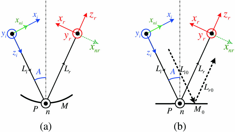
The definitions of TCS and NCS for beam reflection are shown in Fig. 1(a)[3]. For both the TCS and NCS, the axis is always perpendicular to the incident plane of Mirror pointing out of the paper and the axis is a unit vector along the beam propagation direction. The axis of the TCS lies in the incident plane and holds the right-handed coordinates, while the axis of the NCS is identical with the axis of the TCS before reflection and is opposite to it after reflection. Therefore, the TCS always holds right-handed coordinates while the NCS changed to left-handed coordinates after reflection. The specific elements of the ABCD matrix and augmented matrix for optical axis sensitivity analysis must be coincident with the corresponding coordinate system.
Figure 1.(a) Coordinate systems for Gaussian beam reflection from a spherical Mirror ; , incident beam; , reflected beam; (b) simple experiment for comparing TCS and NCS for Gaussian beam reflection; , incident angles; , arbitrarily chosen incident beam; , reflected beam of ; , planar mirror; , binormals at Point ; , reflected points; and , coordinate systems of the incident beam based on the TCS and NCS, respectively; and , coordinate systems of the reflected beam based on the TCS and NCS, respectively.
At first, we would like to take beam reflection analysis of Fig. 1(b) as an example. The ray propagation through an optical component with the augmented Matrix has the form where and are the transverse position of the ray in the and axes; and are the corresponding slopes; the subscripts and mean input and output, respectively; the superscript T stands for transposition. If we use the unit matrix to describe a planar mirror, we must choose the NCS[3,4]. However, we can also choose the TCS, but modify some elements of the augmented transformation matrix for beam reflection. Since the only difference between the TCS and NCS is that their axes are opposite, we can add a minus sign for the elements of the transformation matrix with the NCS corresponding to the axis. For a planar mirror, the transformation matrix will be changed from the unit matrix to . For an arbitrarily chosen beam in the incident plane parallel to the axis in Fig. 1(b), its ray vector is , where is the ray position in the axis. Using Eq. (1), we can obtain the reflected beam with the TCS. If we choose the NCS where the transformation matrix is the unit matrix, the reflected beam is . They in fact represent the same reflected ray. Therefore, whether can we obtain the correct results is determined by whether the coordinate system coincides with the transformation matrix, while application of the TCS in itself cannot be said to be correct or incorrect.
Sign up for Chinese Optics Letters TOC. Get the latest issue of Chinese Optics Letters delivered right to you!Sign up now
There is one drawback when the NCS is used to analyze a ring resonator or sequential reflection. We might as well take the analysis in Ref. [3] as an example. From Fig. 1(a) we know there are two different cases for NCS. In one case, the incident coordinate is right-handed and in the other case, the incident coordinate is left-handed. Therefore, the specific elements of transformation matrix for a spherical mirror are dependent on its position in the resonator, which is very obvious for Eqs. (4)–(5) in Ref. [4]. If we use the TCS, a spherical mirror will have unified elements regardless of its position. The augmented matrix in the NCS of Fig. 1(a) for a spherical mirror can be expressed as where is the curvature of the spherical mirror; is the incident angle; , , , and are elements due to mirror perturbation, which can be found in Ref. [5]. Then the matrix in the TCS should be expressed as
Taking the relationship of expressions for the same ray in the TCS and NCS into consideration, it can be easily proven that is correct using an arbitrary incident ray. Because the TCS is always right-handed, has unified elements independent of their position in an optical system.
It is useful to analyze the example in Fig. 3(c) in Ref. [3] with , where a square ring resonator is used. We use the same Fig. 3(c) and corresponding symbols in this Letter. Only the translational perturbation in the axis is considered for simplicity. If the new reflected point is positive in the TCS, is defined as positive. With this definition, we have , where is the same in Ref. [3]. Using the aforementioned definitions, we can obtain the matrix in the TCS for all mirrors. For planar Mirrors 3 and 4, and for spherical Mirrors 1 and 2, . The (2, 5) matrix elements are for Mirror 3 and for Mirror 4. We can obtain the optical axis perturbation of the axis at Point and Point , which are
The optical axis perturbations of the axis with the NCS in Ref. [3] are
It can be easily seen that the perturbation optical axis is in fact the same optical axis since the axes at Point and Point are opposite for the TCS and NCS.
Next we will take the nonplanar ring resonator (NPRO) as an example to analyze some complicated cases with both the TCS and NCS, which is widely used in ring laser gyros[6,7] and Compton scattering[8]. The geometric configuration of a four-equally sided NPRO is described in detail in Ref. [3], so we do not need to repeat in this Letter. In the NPRO, there are sequential coordinate rotations with the TCS which have the following relationship where is the absolute value of .
If the NCS is chosen, sequential coordinate rotations have the following relationship
It seems that the total coordinate rotation is zero with the TCS at first glance. However, if the property of mirror reflection is considered, the total rotation for polarization vectors, image vectors, skew ray. and Gaussian modes are all . We might as well take the Gaussian beam facular with an elliptical isophote as an example. The modes in a NPRO are usually general astigmatic Gaussian beams, so the azimuth angle of the major axis of beam facular is not always along the transverse axes of the TCS or NCS. Let the azimuth angle of major axis at be . In order to analyze the coordinate rotation of the Gaussian beam, we need to investigate the transformation of general Gaussian beams in one single segment at first. There are several methods can be used to analyze the Gaussian modes in an NPRO. We choose the parameter method in our work[2]. From the analysis in Ref. [3], we have already known the beam rotation angle in one single segment, but the role of the mirror reflection is not considered in detail therein.
The reflection transformation of a tilted mirror for Gaussian beam has been analyzed in Ref. [9]. However, it is only for the case of a simple astigmatic Gaussian beam. We can use the same method to analyze the reflection of a general astigmatic Gaussian beam on a tilted mirror with the TCS. A simple astigmatic Gaussian beam can be described by matrix , where and are the parameters for the and axes, respectively[1]. If the simple astigmatic Gaussian beam rotates anti-clockwise about the propagation direction, the parameter will become[1]
If we choose the TCS, after reflection will become
The imaginary parts of represent beam size[1,2]. Since , we can see that beam shape does not change but its azimuth angle of the major axis is changed from to after reflection. As a result, the azimuth angle will change sign after an odd number of reflections. In the four-equally sided NPRO in Ref. [3], the total coordinate rotation angle is
The total coordinate rotation angle with the NCS is also in Ref. [3]. It is obvious that when we consider the influence of mirror reflection, total coordinate rotation angles with the TCS and NCS are identical. It should be noted that coordinate rotation in NPRO does not mean that the beam shape at the reference point is different from that after one round-trip. Due to the changes of beam facular size in the process of propagation, the self-consistence of beam shape in the NPRO is still satisfied.
Careful analysis shows that the rotation for polarization, image, and ray vector in NPRO obeys similar rules to Gaussian beams[10,11]. Therefore, the coordinate rotation of a NPRO is a general property independent of coordinate selection.
Now we know that the analysis based on both the TCS and NCS have the same results as long as the corresponding matrix is correct. For the orthogonal system where and can be separated, we do not need to add the minus sign for the ABCD matrix in the axis, since
This is just the case in Ref. [9].
For nonorthogonal systems and skew rays, the matrix should be consistent with the selected coordinate. A curved mirror with oblique incidence is evidently not an axial-symmetric system, so the ABCD matrix will be different in the TCS and NCS. However, this problem is not clear in some publications such as p. 585 in Ref. [2]. In Ref. [11], another form of beam transformation matrix for Gaussian beam analysis is derived where the change of the axis due to mirror reflection is considered, so the result is correct. This is also true for the analysis based on Ref. [11], such as Ref. [12]. Careful check shows that analysis of Ref. [13] has taken this into consideration. The matrix in Refs. [14,15] is not consistent with the coordinates but this was revised in Ref. [4].
Both the TCS and NCS can be used to analyze Gaussian beams and optical systems as long as the corresponding matrix is consistent with the coordinate system. The TCS is based on right-handed coordinates and is usually convenient for building a matrix with a unified form. However, there are also cases where the NCS is convenient. For example, when the matrix of a planar mirror can be represented as unit matrix, the analytical description will be concise[16]. This work clarifies some confusion in previous publications and therefore is significant to both Gaussian beam propagation analysis and ring laser resonator design.
Zhiguo Wang, Jie Yuan, Li Yingying, Guangzong Xiao, Hongchang Zhao, Zhichao Ding. Reanalysis on coordinate system for Gaussian beam reflection[J]. Chinese Optics Letters, 2015, 13(Suppl.): S21402