
Haoxuan Si, Lianqiang Shan, Huiyao Du, Li Jiang, Shengzhen Yi, Weimin Zhou, Zhanshan Wang. High-resolution Mo Kα X-ray monochromatic backlight imaging using a toroidal crystal[J]. Chinese Optics Letters, 2023, 21(10): 103401
- Chinese Optics Letters
- Vol. 21, Issue 10, 103401 (2023)
Abstract
1. Introduction
High-resolution X-ray imaging is very important in research fields such as laser-driven inertial-confinement fusion (ICF), high-energy-density physics, and laboratory astrophysics[1–3]. In ICF experiments, high-resolution X-ray monochromatic imaging of the hot spot in the late stages of a pellet implosion is a necessary diagnostic method for studying important physical issues, such as the shape of the hot spot, the temperature distribution, and fuel mixing[4,5]. As the driving energy and implosion mass are increased, the target pellet reaches states of higher energy and density. When the size of the hot spot decreases, the plasma density increases. To enable backlighting or self-emitted X rays to penetrate the higher-density implosion area, X-ray monochromatic imaging optics need to work in the higher-energy X-ray regions (10–30 keV or higher) while simultaneously achieving a high spatial resolution (better than 10 µm)[6–8]. The X-ray optics also require a high collection efficiency to compensate for intensity loss due to the monochromatic nature of the reflected X rays.
The optical properties of a spherical crystal include a large numerical aperture and high spatial and spectral resolution, which have obvious prospects for applications in high-energy X-ray imaging[9,10]. Koch et al.[11] obtained the integrated reflectivity of a Ge bent crystal at the characteristic line (19.7 keV) and evaluated the feasibility of using it in imaging experiments, although they did not conduct imaging experiments themselves. Schollmeier et al.[12,13] presented several simulation results for spherical crystals used for high-energy imaging, employing a Ge backlight-imaging crystal with the characteristic line (17.48 keV). They obtained a theoretical spatial resolution of 3.9 µm. Schollmeier and Loisel also systematically studied the pairing of crystals and emission lines, especially the pairing of many high-energy X rays greater than 10 keV with crystals. At this time, the required Bragg angle is large, so astigmatism correction is required. Storm et al.[14,15] performed imaging experiments using the characteristic line (15.7 keV) with an -quartz spherical crystal, and they obtained its Bragg angle, rocking curve, peak reflectivity, and integral reflectivity. Hall et al.[16] developed a bent-crystal X-ray backlight imager using a Si crystal with the characteristic line (11.6 keV), obtaining a spatial resolution of . Because the focal lengths for the meridional and sagittal directions are inconsistent at oblique incidence, a spherical crystal works well only for Bragg angles greater than 80°, so the detector used for spherical-crystal imaging is generally placed in the middle of the meridional and sagittal focal planes to compensate for astigmatism in both directions, which makes it difficult to obtain an optimal spatial resolution. It is also difficult to find crystal materials with suitable lattice constants to work at near-normal-incidence Bragg angles in the high-energy X-ray region. In addition, effectively shielding the crystal from background noise at near-normal incidence is a challenging technical problem[17].
A toroidal crystal has different curvature radii in the meridional and sagittal directions, which can be used to eliminate severe astigmatism at non-normal incidence. Compared with spherical crystals, the use of toroidal crystals for high-energy X-ray imaging can expand the choice of crystal materials, orientations, and diffraction orders. Toroidal crystals have been previously used in low-energy X-ray imaging experiments. For example, Fujita et al.[18,19] used a Ge toroidal crystal to achieve high-resolution imaging at 3.68 keV. Jiang et al.[20] developed a four-channel Ge toroidal-crystal X-ray imager for the characteristic line (4.51 keV), and they achieved a four-channel spatial resolution of 4.0–9.2 µm in X-ray imaging experiments. Si et al.[4] performed imaging experiments using the line (6.7 keV) with a Ge toroidal crystal, obtaining a spatial resolution of 4–7 µm within an object field of view (FOV) greater than 1.3 mm.
Sign up for Chinese Optics Letters TOC. Get the latest issue of Chinese Optics Letters delivered right to you!Sign up now
However, at present, applications of toroidal crystals to 20 keV-level high-energy X-ray imaging are still lacking. The source-spectrum characteristics have a more serious influence on the imaging performance of a toroidal crystal, so accurate optical simulations are required. On the other hand, X-ray scattering is more serious in the high-energy range, so the necessary ultrathin wafers and toroidal crystals need to be prepared with high accuracy to achieve high resolution.
In this paper, we describe the development of a Ge toroidal crystal for high-resolution monochromatic imaging using the characteristic line, and we demonstrate its potential for applications to 20 keV-level X-ray high-resolution imaging. In Section 2, we introduce the optical design and determine the initial structural parameters of a toroidal crystal for use with the characteristic line. In Section 3, we present an optical simulation of the toroidal crystal and analyze the influence of the structural parameters on its imaging performance. In Section 4, we demonstrate the high-resolution capability that can be obtained by careful preparation of the toroidal crystal and discusses X-ray imaging experiments using a Mo X-ray tube.
2. Optical Design
For bent crystal imaging, the X rays were diffracted conforming to the Bragg condition , where is the lattice spacing, is the Bragg angle, is the diffraction order, and is the wavelength of the X rays. Meanwhile, the imaging relationship of a bent crystal satisfies the paraxial lens equation, i.e., the Coddington equation,
![]()
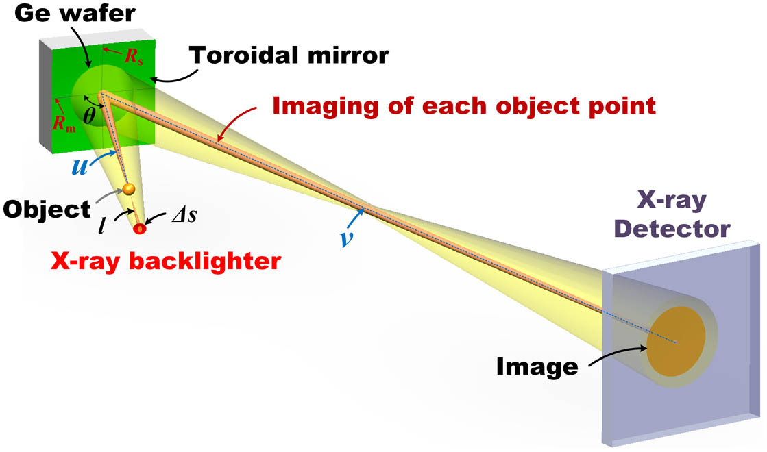
Figure 1.Structure of the optical path in toroidal-crystal optics.
It is necessary to pay attention to the image brightness for high-energy X-ray backlighting imaging optics. On one hand, it is necessary to select a backlighter target with a high conversion efficiency for interacting with a laser beam. On the other hand, relativistic effects need to be considered when a high-energy picosecond laser interacts with a target, and a single-shot light source can generate the characteristic line with sufficient brightness. Compared with the characteristic line and the characteristic line commonly used in the past, the characteristic line has a shorter wavelength and stronger penetration, which enables its use in diagnosing objects with higher areal densities, and it also has significant advantages for diagnosing dynamic physical processes. In this study, we have therefore designed a backlighting imaging system for the characteristic line[21]. Moreover, K-shell characteristic lines can be generated by a common Mo X-ray tube, which can be used directly as the backlighter source for X-ray imaging and calibration experiments with toroidal crystals.
Because the integrated diffraction efficiency of a Ge crystal is higher than that of the commonly used -quartz crystal, we selected a Ge crystal as the optical element for use in this study. The third-order diffraction of Ge crystal direction was selected due to its high diffraction efficiency for 17.48 keV X-rays, and the calculated Bragg angle is 77.74°. Taking the spatial resolution requirements (5–10 µm) and the spatial limitations in the laser facility into account, we designed the optical-structure parameters of a toroidal crystal, as shown in Table 1, where and are, respectively, the object distance and image distance of the toroidal crystal (see Fig. 1). The object distance is the distance between the bent crystal and the target point, which we set to 161.24 mm to avoid spatial interference with the driving lasers and other diagnostic equipment. The imaging magnification is . The spatial resolution of the image detector (FUJI BAS1025SR image plate), about 12 lp/mm with the scanning resolution of 25 µm, restricts the limiting resolved power of the toroidal crystal[22].
| Material | Ge 〈5 1 1〉, n = 3 |
|---|---|
| θ | 77.74° |
| Rm/Rs | 300 mm /286.5 mm |
| Aperture | Φ12 mm |
| u | 161.24 mm |
| v | 1612.4 mm |
| l | 40 mm |
| Δs | 1 mm |
Table 1. Structural Parameters of the Toroidal Bent-Crystal System
3. Performance Simulation
In addition to the structural parameters listed in Table 1, the X-ray energy spectrum, the size of the focal spot, and the backlighter distance also have a considerable influence on the spatial resolution and effective FOV in toroidal-crystal imaging, which we simulated in this study using the ray-tracing software X-ray tracer (XRT). Developed by Klementiev and Chernikov[23], XRT is a Python software library with powerful computing and ray-tracing functions, which can simulate various X-ray sources and optical elements. We used a Mo-target X-ray tube with a focal-spot size of and a backlighter distance of for subsequent X-ray imaging experiments in the laboratory (see Section 4). We measured the distribution of the X-ray spectrum, shown in Fig. 2, at an operating voltage of 31 kV and a current of 20 mA using a silicon shift detector (Amptek XR100-CR). The spectrum includes the two K-shell characteristic lines of Mo and continuum bremsstrahlung. Because of the high monochromaticity of toroidal-crystal imaging, only a narrow-band spectral-energy range of can be reflected. For an illuminated FOV of , the spectrum range is 17.476–17.488 keV, i.e., the energy resolution is about 1450. In the XRT software, we selected 20 equally spaced energy points to simulate the shape of the spectrum over the range of 17.476–17.488 keV, and we placed a 600 lp/inch grid ( with a period of 42 µm and a line width of 6 µm) in the object plane to calibrate the spatial resolution. Other XRT settings were consistent with the design parameters of the toroidal crystal listed in Table 1.
![]()
Figure 2.Distribution of the X-ray energy spectrum from a Mo target.
The XRT simulation results are shown in Fig. 3, where the histogram on the far right is the simulated spectral distribution, and the histograms on the top and right sides of the grid imaging are the local light intensity distributions in the corresponding horizontal and vertical directions.
![]()
Figure 3.(a) Simulation results for the toroidal-crystal imaging of a 600 line-pairs/inch grid as obtained using XRT software. (b) Intensity changes across the 600 line-pairs/inch grid, showing the “80%–20%” resolution-evaluation criterion.
The Bragg angles for toroidal-crystal imaging for different FOVs change gradually, so there are differences in the dispersed energy for different FOVs in Fig. 3(a). Taking into account the spectral shape shown in Fig. 2, the imaging brightness decreases gradually with the FOV deviation. The vertical direction corresponds to the focusing. The imaging brightness is basically the same at most FOVs but decays rapidly in the fringe FOV due to vignetting. In Fig. 3(a), represents the total number of ray-tracing X rays, represents the effective number of X rays incident on the toroidal crystal, and is the total number of X rays reflected into the image plane by the toroidal crystal. The imaging efficiency of the toroidal crystal can be defined as the ratio of to , which is about 1.7%.
We select a strip in Fig. 3(a) to obtain the intensity changes across the image of the grid, as shown in Fig. 3(b). The spatial resolution of the toroidal crystal image can be quantified in terms of the change of intensity at the edges of the gridlines in Fig. 3(b), i.e., , where is the spatial distance corresponding to a peak-to-valley brightness change from 80% to 20%. The calibrated resolution decreases from 2.5 µm in the central FOV to 4.5 µm in FOV. The backlighter size will affect the spatial resolution of the toroidal crystal imaging system. When is reduced to 0.5 mm, the spatial resolution will be further improved to 1.8 µm in the central FOV and 3.5 µm in FOV.
4. Crystal Fabrication and Imaging Experiments
A toroidal crystal is composed of two parts: an ultrathin Ge wafer and a toroidal-mirror substrate. The two are combined using the optical-contact method. The replication effect of the wafer on the substrate depends on the shape of the substrate, the removal of dust between the wafer and the substrate, and the flatness of the wafer, and it is the key to realizing the final imaging resolution. In this study, the parallelism of the crystal plane and the wafer surface was first ground to through the calibration of an X-ray diffractometer (Bruker D8 Discover). We then double-side polished the rough Ge wafer to a thickness less than 100 µm to provide good flexibility. The integral reflectivity was about 40 µrad at 8.048 keV, which had good consistency with the theory value of 44.2 µrad simulated by the XOP software. It also indicated that the Ge wafer was well prepared, and the actual imaging efficiency was close to the simulation value of 1.7%. We controlled the surfaces of both the double-side polished wafer and the toroidal substrate mirror to a roughness better than 1.0 nm, and we cleaned them ultrasonically to strip off the solvent and particles. Finally, we attached the wafer directly to the toroidal substrate mirror by utilizing molecular forces.
We calibrated the spatial resolution of the prepared toroidal crystal through laboratory X-ray imaging experiments with a 600 line-pairs/inch Au grid. We backlit the grid using a Mo X-ray tube with a working voltage of about 31 kV and a current of 20 mA. We placed an X-ray CCD (Photonic Science VHR-11M) with a pixel size of in the image plane as a detector. The imaging results for an exposure time of 30 min are shown in Fig. 4(a). The imaging range is restricted by the aperture edge of the grid. The intensity distribution in the meridional direction gradually weakens from the center to both sides due to the X-ray monochromatic dispersion, while the intensity of the sagittal direction in the same meridional position is basically consistent.
![]()
Figure 4.(a) Imaging of a 600 line-pairs/inch Au grid using the prepared toroidal crystal. (b) Intensity changes across the Au grid, showing the “80%–20%” resolution-evaluation criterion.
We select a strip along the horizontal direction in Fig. 4(a) to obtain the intensity changes across the image of the grid, as shown in Fig. 4(b). Due to the severe scattering of the 17.48 keV X rays, it is difficult to calibrate the spatial resolution by selecting a line distribution. We choose a strip distribution to calibrate, and the intensity change is the average value in the entire strip. Therefore, the strip width has little influence on calibration results of the spatial resolution. The resolution calibrated using the “80%–20%” evaluation criterion is shown in Fig. 5. The results show that the spatial resolution across the entire FOV is about 5–10 µm, which has a certain decline compared to the simulation values shown in Fig. 3. This is caused mainly by the following three factors: (1) The spatial resolution is limited by the pixel size of the X-ray CCD. The corresponding resolution limit for the object plane is about 3.6 µm, as calculated from the size of the two pixels. (2) Figure 3 shows the imaging resolution of an ideal toroidal crystal. The lattice damage that inevitably occurs during the preparation of the actual crystal causes X-ray scattering, which reduces the spatial resolution. (3) The thickness of a gridline is only about 10 µm, and the transmittance of the X rays reaches 10%, which also reduces the sharpness of the gridlines.
![]()
Figure 5.Spatial resolution in the horizontal direction.
5. Conclusion
We have developed a high-energy, high-resolution X-ray-backlighting imaging system based on a toroidal crystal for 20 keV-class X-ray diagnostics in laser-driven ICF experiments. We designed a toroidal crystal of Ge for backlight imaging using the characteristic line. We simulated the imaging performance of the designed toroidal crystal using XRT software, and we evaluated the influence of the backlighter and structural parameters, such as the spectral response, brightness distribution, and spatial resolution of the toroidal crystal, using laboratory imaging experiments. We carried out high-precision preparation of ultrathin wafers and completed their bonding to toroidal-mirror substrates. We obtained calibration results with a spatial resolution of 5–10 µm within FOVs larger than 1.0 mm using a Mo X-ray tube in the laboratory to verify the high-energy, high-resolution imaging capability of the developed toroidal crystal. Using ultrathin wafers of different materials or of different crystal orientations and employing toroidal substrates with different radii of curvature, the toroidal-crystal imaging system developed in this study can be easily applied at other X-ray energies.
The toroidal-crystal system we have developed has good prospects for applications in kilojoule-level laser facilities. On one hand, because the X rays generated by the interaction between a laser and the target have higher intensities than those generated by an X ray tube in the laboratory, the signal intensity from toroidal-crystal imaging in a kilojoule-level laser facility can be expected to be higher. On the other hand, the spot size of the backlighter in a kilojoule-level laser facility is smaller, so we expect the spatial resolution of toroidal-crystal imaging in such a case to be better than 5 µm.
References
[10] S. L. Xiao, Y. J. Pan, X. X. Zhong, X. C. Xiong, G. H. Yang, Z. L. Liu, Y. K. Ding. High-resolution x-ray focusing concave (elliptical) curved crystal spectrograph for laser-produced plasma. Chin. Opt. Lett., 2, 495(2004).

Set citation alerts for the article
Please enter your email address
© Copyright 2018-2021 | Chinese Laser Press. All Rights Reserved 沪ICP备15018463号-20