Abstract
We investigate the principles of optical phase remodulation and demonstrate its application in a future-proof 10 Gb/s/channel wavelength-division-multiplexed (WDM) passive optical network to realize a colorless optical network unit and bidirectional transmission over a single fiber. The modulation depth of downstream differential phase-shift keying is properly reduced to facilitate phase remodulation and Rayleigh noise mitigation. For both downstream and upstream 10 Gb/s signals, error-free transmission via a 20 km single-mode fiber is demonstrated without dispersion compensation operation.The wavelength-division-multiplexed passive optical network (WDM-PON) is an attractive technology to meet the ever increasing bandwidth demand from commercial and residential subscribers[1–7]. To facilitate wavelength management, the WDM-PON architecture with a colorless optical network unit (ONU) has emerged as an attractive solution[8–12]. The colorless ONU can be realized by either a carrier-distributed scheme or a remodulation scheme. In the carrier-distributed scheme, extra laser diodes are needed for the remote provision of an upstream optical carrier, which increases system cost[13]. To avoid this problem, in the remodulation scheme, part of the downstream light is directly reused as the upstream carrier at the ONU. The remodulation cross talk, caused by the residual downstream data, is the key challenging issue of remodulation. This problem can be solved by using properly designed downstream modulation formats, like Manchester coding, on-off keying with a reduced modulation depth (RMD-OOK), or inverse return-to-zero (IRZ) OOK[5]. These modulation formats can work since constant optical power is reserved in each bit, at the expense of degraded downstream receiver sensitivity. The remodulation cross talk can also be mitigated by using downstream differential phase-shift keying (DPSK) and upstream OOK with a full modulation depth (FMD-OOK)[6]. A commercial athermal delay interferometer (DI) can make DPSK-based WDM-PON more practical[14]. Some other remodulation schemes have also been proposed to increase system tolerance to dispersion or remodulation misalignment[7–9]. However, the prior remodulation schemes[5–9], in which bidirectional signals are transmitted at the same carrier wavelength, are vulnerable to the beating noise caused by Rayleigh backscattering (RBS), and for this reason, dual feeder fibers are normally required in demonstration.
To simplify the transmission components in PONs, bidirectional transmission over a single fiber is highly desirable. Due to the loss of the round-trip propagation between the optical line terminal (OLT) and the ONU, in the case of bidirectional transmission over a single fiber, the received upstream signal normally has a relatively small power and will be susceptible to the noise caused by beating between the upstream light and the back-reflected light. There have been extensive studies on Rayleigh noise suppression in WDM-PONs. However, prior schemes are mainly for the carrier-distributed WDM-PON, using light source scrambling, spectral broadening of the upstream signal, wavelength splitting, or specially designed coherent receivers[15–18]. Rayleigh noise mitigation in the remodulation-based WDM-PON is more challenging, and only a few approaches have been proposed. In Ref. [10], to suppress the RBS effect on the upstream channels, the downstream light coherence was reduced by using frequency-shift keying (FSK) in the downstream. However, a 5 dB penalty, at 1 Gb/s, is still observed due to the residual cross talk noise. Subcarrier modulation (SCM) can be used to reduce spectral overlap between the reflections and the signals[11], with a 2.5 Gb/s upstream transmission being demonstrated. Although some orthogonal frequency-division-multiplexing-based schemes can achieve a high bit rate[17], bidirectional transmission over a single fiber has not been demonstrated[19–21].
In this Letter, we investigate the principles of optical phase remodulation and demonstrate its application in a 10 Gb/s WDM-PON with a single feeder fiber and a colorless ONU. RMD-DPSK and FMD-DPSK are used in the downstream and upstream, respectively[12]. At the ONU, a high extinction ratio (ER) can be achieved for the demodulated RMD-DPSK signal from the DI’s destructive port[8]. Meanwhile, the light from the DI’s constructive port has a reduced phase variation and a very low ER, and thus is very suitable as the carrier for upstream phase remodulation. Due to modulation depth (MD) reduction of the downstream signal, the spectral width of its RBS toward the OLT is narrow, and thus can be effectively mitigated by the destructive port of the DI at the OLT, which has a notch filter-like frequency response and is simultaneously used for demodulation of the upstream DPSK signal. In the remaining part of this Letter, we first make a comprehensive comparison between the proposed optical phase remodulation and the conventional optical amplitude remodulation and conclude that the proposed scheme can alleviate the downstream receiver sensitivity degradation. We then investigate the advantage of using the DI’s constructive port output as the upstream carrier. The proposed RBS mitigation scheme will also be analyzed in detail.
Sign up for Chinese Optics Letters TOC. Get the latest issue of Chinese Optics Letters delivered right to you!Sign up now
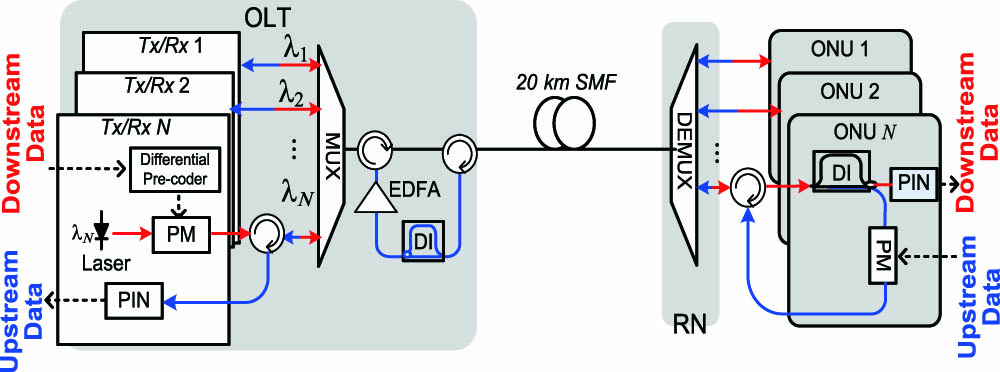
Figure 1 shows the phase-remodulation-based WDM-PON scheme using RMD-DPSK in downstream and FMD-DPSK in upstream. A 20 km single-mode fiber (SMF) is used as the feeder fiber. At the ONU, the output from the DI’s destructive port is used for downstream detection. The optical signal from the DI’s constructive port is used as the upstream carrier for phase modulation[12]. Due to the DI’s periodic frequency response, a common DI at the OLT can be used to simultaneously demodulate all the upstream DPSK channels. By using a shared DI and an cyclic arrayed waveguide grating (AWG) at the remote node (RN), the DI at the ONU can be also saved[6].

Figure 1.Proposed optical phase remodulation architecture. EDFA: erbium-doped fiber amplifier; PM: phase modulator; PIN: p-i-n receiver; MUX: multiplexer; DEMUX: de-multiplexer.
For the demodulated RMD-DPSK signal from the DI’s destructive port, its ER is independent of MD and can be infinite, theoretically[8–12]. Figures 2(a) and 2(b) depict the simulated eye diagrams of the demodulated downstream RMD-DPSK signal from the destructive port of the DI, when the RMD-DPSK signal’s MDs are 0.2 and 0.4, respectively. Compared with the eye diagram of the demodulated FMD-DPSK signal, as in Fig. 2(c), a certain power reduction in the “1” level is observed, whereas the demodulated “0” level is always perfectly null, leading theoretically to an infinite ER. In practice, although the ER cannot be infinite due to device imperfections and additional noise, it can achieve a high value when the phase MD varies in a large range. On the other hand, for the signal from the constructive port, the ER is obviously reduced, as in Figs. 2(d) and 2(e), and thus can be used as the upstream carrier via phase remodulation.
Figure 2.Eye diagrams with different downstream MDs: (a)–(c) downstream DPSK signal, demodulated from the destructive port of the DI; (d)–(f) DPSK signal in the downstream, demodulated from the constructive port of the DI; (g)–(i) downstream OOK signal in the conventional optical amplitude remodulation scheme.
As shown in Fig. 3(a), when the MD of the RMD-DPSK signal in the downstream is reduced, the insertion loss for the destructive port of the DI will increase. As the MD of the downstream RMD-DPSK signal decreases, its spectrum width becomes narrower, as shown in the inset of Fig. 3(a). Thus, for the downstream RMD-DPSK signal with a smaller MD, more power will be suppressed by the DI’s destructive port with a notch filter-like frequency response, leading to an increased insertion loss. The MD of the RMD-DPSK data in the downstream thus should not be too small—to ensure enough downstream power budget. Nevertheless, from the principle of conservation of energy, the reduced optical power actually outputs from the DI’s constructive port[8]. Here, the constructive port output is used as the optical carrier for phase remodulation, and no optical power is wasted.
Figure 3.(a) Insertion loss for the destructive port of the DI for the RMD-DPSK signal in the downstream, at different downstream MDs. Inset: the simulated spectrum of the RMD-DPSK signal in the downstream with different MDs. (b) Impact of the downstream MD on the receiver sensitivity of both the downstream and upstream signals when using different remodulation schemes. Detected eye diagrams of the FMD-DPSK signal in the upstream (c) when using the constructive port output from the DI as the upstream carrier and (d) when using part of the RMD-DPSK data in the downstream as the upstream carrier. (e) Detected eye diagrams of the FMD-OOK signal in the upstream when using conventional optical amplitude remodulation. The downstream MD in (c)–(e) is 0.4.
We then investigated the impact of the downstream MD on the receiver sensitivity of both the RMD-DPSK signal in the downstream and the FMD-DPSK signal in the upstream through simulation, and the results are reported in Fig. 3(b). As the downstream MD decreases, there is no power penalty for the demodulated RMD-DPSK data in the downstream due to its high ER, as discussed above. Actually, even a slightly negative power penalty is observed, arising from the return-to-zero (RZ)-like pulse shape of the RMD-DPSK data. For comparison, we also studied the relationship between the downstream MD and the receiver sensitivity for the conventional optical amplitude remodulation scheme. As shown in Fig. 3(b), the power penalty of the downstream RMD-OOK signal increases rapidly as the MD of the downstream OOK signal decreases. The power penalty of the RMD-OOK data in the downstream is due to the reserved optical power in each bit that actually carries no information, as shown in Figs. 2(g) and 2(h). Both remodulation schemes have similar upstream performance when the downstream MD changes, as reported in Fig. 3(b) (the open circle and open square). When the downstream MD is 0.4, eye diagrams of the detected signal in the upstream via the proposed optical phase remodulation scheme and the conventional optical amplitude remodulation scheme are shown in Figs. 3(c) and 3(e), respectively, with similar eye openings.
Using the output from the constructive port of the DI as the upstream carrier not only avoids power waste due to the relatively large insertion loss of the DI’s destructive port, it also reduces phase variation in the upstream carrier by half, compared to that when part of the RMD-DPSK data in the downstream is used as the upstream carrier. Assume that “0” and “” are the two symbols of the RMD-DPSK signal in the downstream, where , depending on the downstream MD. Each bit of the DI’s constructive port output is the summation of two adjacent bits of the downstream RMD-DPSK signal. Thus, if both of the two adjacent bits have the same phase of “0” or “,” their summation from the DI’s constructive port will have a phase of “0” or “,” respectively; and, if the two adjacent bits have different phase symbols, their summation from the DI’s constructive port will have a phase of “.” From the aforementioned analysis, we can derive that there are three possible demodulated phase symbols in the DI’s constructive port output, namely, “0,” “,” and “.” Interestingly, in the DI’s constructive port output, the phase symbols “0” and “” cannot be adjacent, as the demodulated “0” is from two consecutive “0” in the RMD-DPSK data in the downstream, whereas the demodulated “” is from two consecutive “.” When “0” is adjacent to “” in the downstream RMD-DPSK signal, a phase symbol of “” will be generated in the DI’s constructive port output. This means that in the DI’s constructive port output, between the phase symbols “0” and “,” there is at least one phase symbol of “.” Thus, the maximum phase variation in the upstream carrier is reduced to , instead of , if using the demodulated signals from the DI’s constructive port, rather than part of the downstream RMD-OOK signal, as the upstream carrier. Thus, for the upstream FMD-DPSK signal, the reduced phase variation will result in smaller cross talk from the residual downstream signal, as shown in Fig. 3(b) (the open triangle and open square). Comparing Fig. 3(c) with Fig. 3(d), we find that the demodulated upstream FMD-DPSK signal has a wider eye opening when using the DI’s constructive port output instead of the RMD-DPSK data in the downstream as the remodulation carrier.
Since the frequency response of a DI’s destructive port is like that of a notch filter, RBS light toward the OLT, with a spectrum as narrow as that of the RMD-DPSK data in the downstream, can be effectively suppressed by the destructive port of the OLT DI. As the downstream MD increases, the RBS spectrum toward the OLT will become wider; thus, less RBS can be suppressed by the destructive port of the OLT DI. To evaluate the effectiveness of the proposed scheme on RBS suppression, we have measured the RBS spectrum passing through the DI, based on the setup shown in Fig. 4(a). The downstream RMD-DPSK signal is launched into a 20 km SMF via an optical circulator. The far end of the SMF is terminated by an optical terminator to avoid reflection. The RBS light, generated in the 20 km SMF, propagates back and enters the DI via the optical circulator. An optical spectrum analyzer is used to measure the input and output spectra of the DI. Note that this setup is based on the OLT structure in Fig. 1. From Figs. 4(b)–4(d), we can see that the constructive port of the DI has a negligible effect on RBS, whereas the destructive port of the DI can significantly suppress the RBSs by 19, 16, and 13 dB when the downstream MDs are 0.18, 0.31, and 0.43, respectively. Thus, the proposed optical phase remodulation scheme is more robust with respect to RBS noise when the downstream MD is smaller.
Figure 4.(a) Experimental setup used to study the effect of the DI’s two output ports on RBS suppression. CP, constructive port; DP, destructive port. (b)–(d) Measured spectra of the RBS before and after the DI when the downstream MDs are 0.18, 0.31, and 0.43, respectively (resolution ).
In order to verify the effectiveness of optical phase remodulation in Rayleigh noise suppression, the proposed remodulation scheme has been experimentally demonstrated based on the WDM-PON architecture in Fig. 1. For the detailed experimental setup, please refer to Ref. [12]. The open eye diagram of the demodulated downstream RMD-DPSK signal from the ONU DI’s destructive port is shown in Fig. 5(a), with an ER of . Meanwhile, a clear eye diagram of the upstream FMD-DPSK signal, being demodulated by the OLT DI’s destructive port, is also shown in Fig. 5(a).
Figure 5.(a) Eye diagrams of the detected downstream RMD-DPSK and upstream FMD-DPSK signals in the B2B and transmission cases. DS, downstream; US, upstream. (b) BER measurement results when the downstream MD is 0.22. (c) BER measurement results when the downstream MD is 0.18 and an SOA is used at the ONU.
The two output ports of the DI, namely the constructive port and destructive port, are equivalent in demodulating DPSK signals, as can be seen in Figs. 2(c) and 2(f). However, only the destructive port can be used as a RBS suppressor for the upstream signal. The constructive port has a low-pass frequency response, implying that it cannot reject the RBS light toward the OLT. As shown in Figs. 4(b)–4(d), the RBS spectrum can hardly be rejected by the constructive port of the DI, whereas it can be effectively suppressed by the destructive port. For comparison, if the constructive port is used for upstream DPSK signal demodulation, the eye diagram, as shown in Fig. 5(a), will be severely degraded by the RBS noise after transmission in the 20 km SMF, although the eye diagram is wide open in the back-to-back (B2B) case without RBS noise.
The bit-error-rate (BER) for both the downstream and upstream signals has been measured, as shown in Fig. 5(b). After a 20 km transmission via an SMF, with no chromatic dispersion compensation, the measured receiver sensitivity (at ) for the RMD-DPSK data in the downstream is , while that for the FMD-DPSK data in the upstream is . A power penalty of around 4 dB is observed for the FMD-DPSK data in the upstream due to chromatic dispersion. Thanks to the narrow spectral width of the RMD-DPSK data in the downstream, the data suffer a negligible dispersion-induced power penalty, as can be seen in Fig. 5(b). To study the effectiveness of the proposed scheme on RBS mitigation, the effect of dispersion is isolated by adding a dispersion compensation module (DCM) to the link. For both the downstream and upstream signals, the power penalty, after a 20 km transmission with the DCM, is reduced to around 0.3 dB, as shown in Fig. 5(b), implying that the proposed scheme is very robust to RBS noise. To investigate the power penalty of the RMD-DPSK data in the downstream induced by the RMD, we also measure the downstream BER performance when the FMD-DPSK signal is used in the downstream. Compared to the FMD-DPSK signal, the RMD induces a power penalty of around 2.1 dB in the B2B case, instead of a slightly negative power penalty in simulation, as reported in Fig. 3(b), resulting from the limited ER of the downstream DI. The RMD-DPSK signal is more robust with respect to dispersion than the FMD-DPSK signal due to its narrower spectrum. Thus, the sensitivity gap between the FMD-DPSK and RMD-DPSK signals is narrowed from 2.1 to 1 dB, after transmission via a 20 km SMF. Note that the receiver sensitivity will be degraded by more than 9 dB when the MD of the downstream OOK signal is reduced from 1 to 0.22 in the conventional optical amplitude remodulation scheme, as can been seen in Fig. 3(b).
In practical implementation, a semiconductor optical amplifier (SOA) can be placed at the ONU to improve the system power budget. We then experimentally demonstrated the proposed remodulation scheme with an SOA before the DI at the ONU. By employing an SOA at the ONU to achieve better power budget, the downstream MD can be smaller. The MD of the RMD-DPSK signal in the downstream was reduced from previous value of 0.22 to 0.18. A 100 GHz AWG (3 dB bandwidth: 0.35 nm) with 4 dB insertion loss was used at the OLT. Another AWG with the same specification was used at the RN. An optical signal with a power of 5 dBm was coupled into the 20 km SMF without the DCM. The received power at the ONU was approximately bg , which was amplified to 2 dBm by an SOA, before being fed in to the DI at the ONU. The BER results for both the upstream and downstream signals are depicted in Fig. 5(c). For the RMD-DPSK data in the downstream, no obvious power penalty can be observed after a 20 km transmission over an SMF. The downstream receiver sensitivity is around at a BER of . For the FMD-DPSK data in the upstream, the measured receiver sensitivities are and , respectively, for the B2B case and the 20 km transmission case. A power penalty of around 3.9 dB can be observed after transmission over a 20 km SMF without the DCM, mainly due to dispersion.
In conclusion, we propose a novel phase remodulation scheme for a WDM-PON with a colorless ONU and enhanced tolerance to RBS noise. For both downstream and upstream 10 Gb/s signals, error-free transmission via a 20 km SMF is demonstrated without a dispersion compensation operation. The power penalty of the RMD-DPSK data in the downstream induced by the MD reduction is effectively reduced, compared with the conventional optical amplitude remodulation scheme. The proposed optical phase remodulation scheme is also robust to RBSnoise; thus, bidirectional transmission at the same carrier wavelength over a single fiber is achieved with a significant simplification in transmission components and a reduction in system cost.
References
[1] M. Presi, R. Corsini, M. Artiglia, E. Ciaramella. Opt. Express, 23, 22706(2015).
[2] Z. Zhang, X. Jiang, J. Wang, X. Chen, L. Wang. Chin. Opt. Lett., 13, 020603(2015).
[3] O. Ozolins, V. Bobrovs. Chin. Opt. Lett., 13, 060603(2015).
[4] C. Li, X. Qiu, X. Li. Photon. Res., 5, 97(2017).
[5] H. S. Chung, B. K. Kim, K. Kim. ETRI J., 30, 255(2008).
[6] X. F. Cheng, Y. K. Yeo, Z. W. Xu, Y. X. Wang. European Conference and Exhibition on Optical Communication, 20(2009).
[7] J. Zhao, L. K. Chen, C. K. Chan. Optical Fiber Communication Conference and the National Fiber Optic Engineers Conference, OWD(2007).
[8] J. Xu, L. K. Chen. IEEE Photon. Technol. Lett., 22, 456(2010).
[9] C. W. Chow, Y. Liu, C. Kwok. Optical Fiber Communication Conference and the National Fiber Optic Engineers Conference, OTHT2(2008).
[10] J. Prat, V. Polo, C. Bock, C. Arellano. IEEE Photon. Technol. Lett., 17, 702(2005).
[11] A. Chowdhury, H. C. Chien, M. F. Huang, J. Yu. IEEE Photon. Technol. Lett., 20, 2081(2008).
[12] J. Xu, L. K. Chen. Optical Fiber Communication Conference and the National Fiber Optic Engineers Conference, OThG3.(2010).
[13] J. Xu, X. Y. Yu, W. C. Lu, F. Z. Qu, N. Deng. Opt. Commun., 346, 106(2015).
[14] X. Liu, A. H. Gnauck, X. Wei, J. Y. C. Hsieh, V. Chien. IEEE Photon. Technol. Lett., 17, 2610(2005).
[15] H. Feng, S. Xiao, Q. Zhou, J. Ge, M. Fok. Opt. Express, 22, 22673(2014).
[16] K. Y. Cho, U. H. Hong, S. P. Jung, Y. Takushima, A. Agata, T. Sano, Y. Horiuchi, M. Suzuki, Y. C. Chung. Opt. Express, 20, 15353(2012).
[17] C. W. Chow, C. H. Yeh, L. Xu, H. K. Tsang. IEEE Photon. Technol. Lett., 22, 1294(2010).
[18] C. W. Chow, G. Talli, A. D. Ellis, P. D. Townsend. Opt. Express, 16, 1860(2008).
[19] H. He, J. Li, M. Bi, W. Hu. Chin. Opt. Lett., 12, 040603(2014).
[20] E. Hugues-Salas, R. Giddings, X. Jin, J. Wei, X. Zheng, Y. Hong, C. Shu, J. Tang. Opt. Express, 19, 2979(2011).
[21] S. Mhatli, M. Ghanbarisabagh, L. Tawade, B. Nsiri, M. Jarajreh, M. Channoufi, R. Attia. Opt. Lett., 39, 6711(2014).