Abstract
In this study, a point-scattering approach to the plane-wave optical transmission of subwavelength metal nanoslit arrays with varying angles of rotation and that of subwavelength metal supercell arrays consisting of nanoslits capable of various angles of rotation is developed. It is demonstrated that the suggested theories show good agreement with the simulations and experiments. The results show that constructive and destructive interference at each nanoslit can respectively enhance and suppress the surface plasmon polariton (SPP) far-field radiation of a metasurface. The proposed theory can predict the quantity and resonant wavelength of SPPs and provide a design scheme for an SPP device.1. INTRODUCTION
A surface plasmon polariton (SPP) [1] is an electromagnetic excitation that propagates in a wave-like pattern along the planar interface between a metal and a dielectric medium (often a vacuum) and whose amplitude decays exponentially with increasing distance into every medium following the interface. SPPs were first observed by Wood in 1902. He observed unexplained features in measurements of optical reflection from metallic gratings [2]. In 1998, Ebbesen et al. observed similar anomalous optical transmissions in a subwavelength periodic metal nanostructure [3]. Later in 1998, Ghaemi et al. proposed a theory to explain this phenomenon [4]. At present, SPPs find extensive applications in surface-enhanced Raman spectroscopy (SERS) [5], solar cells [6,7], and sensors [8]. Researchers have proposed several models, such as the mode expansion method [9], coupled-mode equation [10], and Fano formula [11], to understand the spectra of periodic subwavelength hole arrays. In particular, all classes of SPP modes in periodic subwavelength hole arrays were studied by matching momentum changes of conventional reciprocal-space definitions [3,4,12]. In 2005, Genet et al. reproduced Huygens’ definition for the resonance of subwavelength hole arrays from a real-space description [13]. In 2008, Pacifici et al. studied universal optical transmission features in periodic and quasiperiodic hole arrays and proposed that the positions in the theoretical prediction by Genet et al. are the transmission minimum and not the transmission maximum [14]. However, although such models have predicted the resonant frequency of periodic isotropic hole arrays, few theoretical studies have focused on anisotropic hole arrays [9]. In recent years, the development of metasurfaces [15–18] has resulted in the need to freely control the amplitude and phase of electromagnetic waves. Owing to their unique properties, anisotropic hole arrays [19,20] are widely used in metasurfaces in applications such as metafocusing of SPPs [21], polarization-controlled tunable directional coupling of SPPs [22], spin optics in conic-shaped metasurfaces [23], flexible coherent control of the plasmonic spin-Hall effect [24], controlled steering of Cherenkov surface plasmon wakes [25], and helicity-dependent directional SPP excitation [26]. These studies focused on near-field information and related applications. However, few studies have focused on far-field radiation information of metasurfaces comprising anisotropic holes arrays. Further, a theoretic model to explain relevant phenomena is needed urgently. In this study, the transmittance spectra of a composited subwavelength nanostructure consisting of various nanoslits rotated at different angles were evaluated theoretically and through simulations. The results demonstrate that the theory correlates with the simulation. Furthermore, the transmission spectra of a metasurface consisting of various nanoslits rotated at different angles were evaluated theoretically and through simulations and experiments. The results demonstrate that both constructive and destructive interference among the fields of the nanoslits at different angles of rotation can make the SPP far-field radiation appear and disappear. It follows that our theory can freely control the excitation and suppression of SPP far-field radiation and may contribute to further engineering of nanoplasmonic devices.
2. METHOD
The dielectric constant for a metal thin film is generally described using the Drude model. Based on the momentum matching proposed by Ebbesen et al., the resonant frequency of the SPP (, ) mode is satisfied by the following equation [4]: where and are integers. and represent the metal bulk plasmon frequency and damping loss, respectively. is the speed of light in vacuum and is the dielectric constant of the dielectric material; and are the period of the and directions, respectively. The gold film used had thickness of , and the nanoslit had length of and width of . The bulk plasmon frequency of gold is and the plasmon amplitude damping loss rate is . The refractive index of the glass is 1.45. Based on Eq. (1), the resonant wavelengths of SPPs at the interface between the gold and glass medium are , , and . The subscript denotes the glass. The resonant wavelengths of SPPs at the interface between the gold and air medium are and . The subscript denotes air. These SPP modes have been confirmed experimentally [3].
The above theory concerning the SPP mode is based on a reciprocal-space definition. In 2005, Genet et al. [13] explained these phenomena from a real-space description based on Huygens’ principle. However, these theories, whose setup is based on isotropic hole arrays, cannot describe the SPP mode for anisotropic hole arrays and cannot describe the SPP of a metasurface consisting of nanoslits at various rotating angles. From Genet’s theory to explain the SPP mode for anisotropic hole arrays and a metasurface, it is assumed that (1) the incident plane wave is converted into a surface wave at a given point within the scatter, (2) the surface wave propagates on the surface of the array, and (3) the surface wave is eventually re-emitted as a plane wave through the array. Considering the anisotropic properties of rectangular hole arrays, Genet’s theory could be generalized.
Sign up for Photonics Research TOC. Get the latest issue of Photonics Research delivered right to you!Sign up now
Figure 1 shows the design scheme of the anisotropic hole arrays. The picture covers one period. The and direction periods are set as and , respectively. For convenience, we define the translational coordinate system with the nanoslit’s center as , and we define the rotating coordinate system as ; it is fixed on the nanoslits and rotated with the nanoslits all together. The angle between the axis (also referred to as the normal direction of a nanoslit) and axis is called the rotating angle of the nanoslit. The origin O of the fixed coordinate system is set as the first, lower-left nanoslit’s center, at the first row and the first column. The position vector of the hole’s center at the th row and th column relative to O is thus where and are the unit vectors of the and axes, respectively.
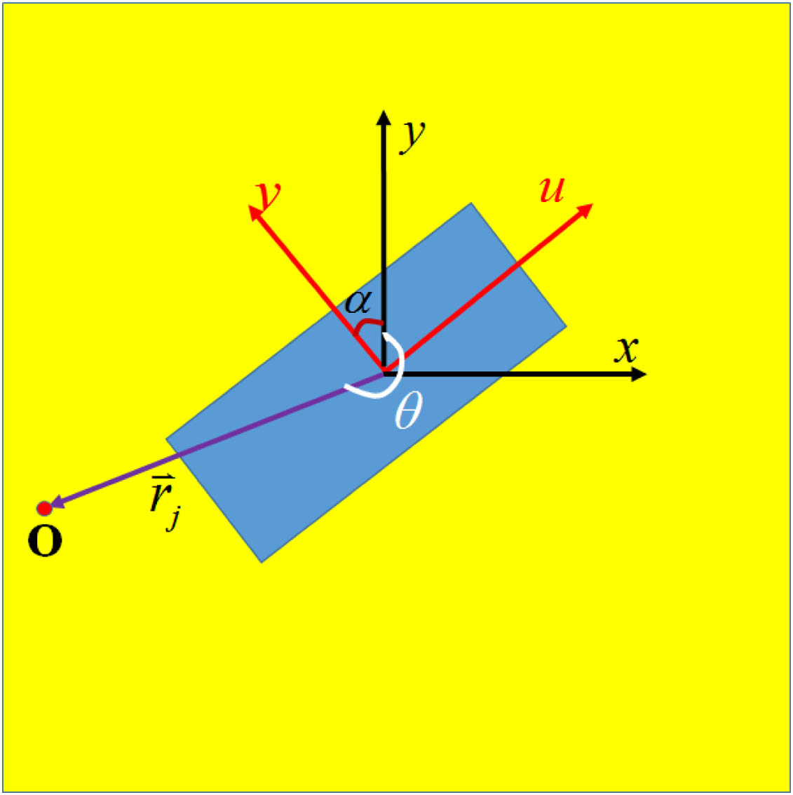
Figure 1.Scheme of the unit cell and corresponding coordinate system.
The unit vector for the position vector is . In our model, the polarization of each surface wave is taken along its propagating direction, with a unitary polarization vector . Basing on Huygens’ principle and considering a single-resonance approximation, when the incidence plane wave is normal to the small hole, the exciting SPP is the same as the point source. The total polarization of the SPP can thus be described by the following tensor [13,27]: We assume that the scattering matrix of the far field is spherically symmetric [13]. The complex amplitude of the transmittance is thus calculated as where and correspond to the wave number of the SPP and the incident wave, respectively. Considering the normal incidence of the plane wave on the metamaterial, we obtain as the scattering amplitude under the far-field approximation and as the shape factor of the nanoslits. Under the point scatter limit, we deduce that has no relationship with , and, thus, can be set as a constant. For anisotropic nanoslits, we deduce that the propagation direction of the SPP contains the effect of the structural shape. The SPP originating from the plane wave and incident on the anisotropic nanoslit shows directional selectivity. The polarization of the incident plane wave is thus set as the direction along the axis, that is , and the excited SPP propagates along the normal direction of the nanoslits [22], as shown in Fig. 1. In Cartesian coordinates , is defined as The propagation direction of SPP is therefore expressed as The transmittance complex amplitude of the total periodic nanostructure is [23,28] When the integers and are set as , the spectrum is stable and convergent. We define the spectrum for as a normalized coefficient . The normalized spectrum is thus represented as Based on Eq. (8), the resonant wavelength corresponds to the minimal transmission and, thus, it is not the maximum transmission [14]. Thus, the corresponding resonant wavelength for the SPP mode is larger than the above-mentioned value.
Based on Eq. (8), under normal incidence of the -polarized plane wave, Fig. 2 shows both theoretical and simulated transmittance spectra with nanoslit arrays at different rotation angles. The solid red (or dashed green) curve represents the SPP mode of the interface between the gold and glass (or gold and air) planes. The notations in red and green font indicate the order of the corresponding SPP mode. Figures 2(a), 2(c), and 2(e) show the theoretical transmittance spectra with respective angles of rotation of 0°, 30°, and 60°. When the angle of rotation is 0°, the theory predicts SPP and SPP at the glass plane. For nonzero angles of rotation, the tilted nanoslit arrays assume the function of optical rotation [29]. Then, other polarization SPP modes are converted. SPP and SPP are observed. To further verify the theory, finite difference time domain (FDTD) simulations were performed. The material and structural properties were kept the same in the simulations. Figures 2(b), 2(d), and 2(f) show the simulated spectra of the periodic nanoslit arrays with respective angles of rotation of 0°, 30°, and 60°. The results demonstrate a reasonable correlation between the theory and the simulation. The discrepancy between the theoretical and the simulated results can be attributed to a closer resonance location of SPP and SPP and their overlapping transmission peak at .

Figure 2.(a), (c), and (e) Calculated and (b), (d), and (f) simulated transmittance spectra of the nanostructure corresponding to the different angles of rotation for polarization. Here, the solid red (dashed green) curves represent the SPPs of the interface between metal and glass (metal and air); the blue solid curves represent the simulated spectra.
Through our simulation, we could verify that the transmission peak of SPP and SPP between the glass and metal planes was strong; however, the transmission peak of the higher-order SPP was weak. This raises a number of questions. (1) Can the lower-order SPP be suppressed? (2) Can the higher-order SPP be enhanced through structural design? (3) Can the SPP excitation be selected freely? These are particularly important considerations. In recent years, it was widely argued that a gradient metasurface could convert the propagation wave to a surface wave and could freely control the phase and amplitude of an electromagnetic wave [16–18]. Experiments were aimed at finding a suitable gradient metasurface to allow free control of SPPs’ far-field radiation. Simultaneously, this would need to be supplemented by a theory to guide the design of this type of metasurface. In our model, there exist a variety of nanoslits in a supercell, as shown in Fig. 3. For convenience, the origin O of the fixed coordinate system is fixed at the center of the first nanoslit, in the first lower-left supercell of the array. The disposition vector of the center of the first nanoslit in the th (the th row and the th column) supercell is . In this supercell, the relative coordinate of the center of the th nanoslit’s center relative to the first nanoslit’s center in the same supercell is set as , as shown in Fig. 3. The absolute coordinate of the th nanoslit’s center is . Based on Fresnel diffraction [13] and the preceding discussion, the total transmission intensity of our metasurface is where (, ) is a normalized coefficient similar to those specified above. Based on Eq. (9), we can thus predict the mode quantity and corresponding resonant wavelength of the SPPs.
Figure 3.Coordinate vector picture of the metasurface.
3. RESULTS AND DISCUSSION
To verify our theory, the test metasurface is shown in Fig. 4. Figures 4(a) and 4(b) show schematic diagrams of metasurface. The periods in the and directions are set as and , respectively. The thickness of the gold film was . The length and width of the nanoslits were and , respectively. The distance between centers for two adjacent nanoslits was and . The supercell of the metasurface consisted of six nanoslits set at different angles. The difference in the angle of rotation between two adjacent nanoslits along the direction was 60°; however, the difference in the angle of rotation between two adjacent nanoslits along the direction was 90°. The red arrow represents the long-edge direction of the nanoslits. The angles formed at the intersection between this direction and the axis are , , , , , and . They also correspond to the intersection angles between the axis and the axis. Based on Eq. (9), the theoretical spectra for - and -polarization are shown in Figs. 5(a) and 5(b), respectively. Because the theory predicts that the transmittance dip has a wavelength for an SPP that is larger than 960 nm, it can be observed that the - or -polarization spectra have only one mode at .
Figure 4.(a) and (b) Schematic diagrams of our supercell. (c) SEM image of the sample with scale bars of 1000 and 800 nm.
Figure 5.(a) and (b) Calculated, (c) and (d) simulated, and (e) and (f) measured spectra of metasurface.
Figures 5(c) and 5(d) show the simulation spectra. Only one transmittance peak can be observed at . The simulation correlates well with the theory. Furthermore, to further verify the theory experimentally, an 80-nm-thick gold film was sputtered on the polished BK7 glass substrate. A 2D nanoslit array was fabricated using a focused-ion beam system (Strata FIB 201, FEI Co., 30 keV Ga ions, 4 pA beam current). The other parameters were kept the same as those for the previous metasurface design. The super-periodic array consisted of units covering an area of . Figure 4(c) shows a typical scanning electron microscope (SEM) image of a part of the sample. In the experiment, the transmission and reflection spectra of the samples were measured using custom-built NIR setup. A quasi-collimated beam of 2 mm diameter from a super-continuum white light source (Fianium S480) with spectral range of 0.48–2.4 μm was focused on the samples with a long-working-distance lens (Mitutoyo 378-804-2, , working distance 20 mm). A linear polarizer and an attenuator were placed before the object to obtain the desired polarization incident wave with suitable intensity. The transmission and reflection signals collected by another identical object were measured using an optical spectrum analyzer (NIR2500 from Ideaoptics). The reference transmission signal was set without the sample. The reference reflection signal for the 80-nm-thick gold film was also set without the sample. Figures 5(e) and 5(f) show the experimental spectra under and polarizations. The experimental spectra show only one mode. The experimental results in Figs. 5(e) and 5(f) are in close correlation with the numerical simulations. The discrepancy between the theoretical and the experimental results can be attributed to fabrication and measurement errors originating from the exciting wavelength of of the laser source.
While analyzing the data, questions arise as to why only one mode is observed at the transmittance spectra for the specific metasurface. Though the above theory can predict the quantity and disposition of SPPs, complete information is contained in the summation signal, and thus, one cannot see its physical mechanism. Thus, to study this mechanism, the transmittance and reflection complex amplitude of the period nanostructure consisting of one nanoslit in the unit cell at different angles of rotation was simulated. The periods in the and directions are and , respectively. The thickness of the gold film was 80 nm. The length and width of the nanoslits were 300 nm and 100 nm, respectively. Figures 6(a) [Fig. 6(b)] and 6(c) [Fig. 6(d)] show the transmittance (reflection) intensity diagrams and transmittance (reflection) phase diagrams, respectively. The transmittance intensity and phase of the periodic nanostructure, with six different angles of rotation (0°, 60°, 90°, 120°, 150°, and 210°) at (1462 and 927 nm) are represented by six purple squares (green stars and black inverted triangles) in Figs. 6(a) and 6(c). At , one can observe that the transmittance intensity of three nanostructures with angles of rotation of 0°, 150°, and 210° is either similar or higher than that of the other three nanostructures, and the transmittance phase of these three nanostructures is almost identical. The constructive interference among these three nanostructures’ fields leads to the emergence of a transmission peak. However, at , the transmittance of six nanostructures is very weak, resulting in the SPP of the interface between the metal and the glass medium being suppressed. At , the transmittance intensity of three nanostructures with angles of rotation of 0°, 150°, and 210° is almost identical, and is higher than that for the other three nanostructures. However, the transmittance phase difference between the nanostructure with angle of rotation of 0° and the nanostructures with angles of rotation of 150° and 210° is 180°. Destructive interference occurs among these three nanostructures’ fields, and thus, the transmission peak disappears. Similar explanations hold for -polarization.
Figure 6.(a) Transmittance intensity, (b) reflection intensity, (c) transmittance phase, and (d) reflection phase diagrams of the test metasurface with nanoslit rotation angles under normal incident plane wave with polarization.
4. CONCLUSION
In conclusion, by using Huygens’ principle, we obtain a theoretical equation to explain the transmittance spectra of a metasurface. The results show that the theory agrees well with the simulations and experiments. The study shows that the angle of rotation of nanoslits in the supercell can be adjusted to freely control the SPPs’ far-field radiation. In addition, the theory can be applied to an aperiodic nanoslits system and thus provide a design scheme for an SPP device.
Acknowledgment
Acknowledgment. We thank Q. He, S. Y. Xiao, and L. Zhou (Fudan University) for their help with this study. We thank F. Shi (Anhui Normal University) for her help with this discussion. Xiyue Zhang measured the transmission and reflection spectra; Qianjin Wang fabricated the test metasurface sample; Maosheng Wang calculated the spectra theoretically; Chaogang Li simulated the spectra; and Kuanguo Li, Xinyan Yang, and Jianping Shi contributed to the discussion.
References
[1] A. V. Zayats, I. I. Smolyaninov, A. A. Maradudin. Nano-optics of surface plasmon polaritons. Phys. Rep., 408, 131-314(2005).
[2] R. W. Wood. On a remarkable case of uneven distribution of light in a diffraction grating spectrum. Philos. Mag., 4, 396-402(1902).
[3] T. W. Ebbesen, H. J. Lezec, H. F. Ghaemi, T. Thio, H. J. Wolff. Extraordinary optical transmission through sub-wavelength hole arrays. Nature, 391, 667-669(1998).
[4] H. F. Ghaemi, T. Thio, D. E. Grupp, T. W. Ebbesen, H. J. Lezec. Surface plasmons enhance optical transmission through subwavelength holes. Phys. Rev. B, 58, 6779-6782(1998).
[5] A. Nemetz, U. Fernandez, W. Knoll. Surface plasmon field-enhanced Raman spectroscopy with double gratings. J. Appl. Phys., 75, 1582-1585(1994).
[6] Y. Wang, X. Su, Y. Zhu, Q. Wang, D. Zhu, J. Zhao, S. Chen, W. Huang, S. Wu. Photocurrent in Ag-Si photodiodes modulated by plasmonic nanopatterns. Appl. Phys. Lett., 95, 241106(2009).
[7] D. Derkaces, S. H. Lim, P. Matheu, W. Mar, E. T. Yu. Improved performance of amorphous silicon solar cells via scattering from surface plasmon polaritons in nearby metallic nanoparticles. Appl. Phys. Lett., 89, 093103(2006).
[8] C. Genet, T. W. Ebbesen. Light in tiny holes. Nature, 445, 39-46(2004).
[9] J. Bravo-Abad, F. J. García-Vidal, L. Martín-Moreno. Resonant transmission of light through finite chains of subwavelength holes in a metallic film. Phys. Rev. Lett., 93, 227401(2004).
[10] H. Liu, P. Lalanne. Microscopic theory of the extraordinary optical transmission. Nature, 452, 728-731(2008).
[11] C. Genet, M. P. van Exter, J. P. Woerdman. Fano-type interpretation of red shifts and red tails in hole array transmission spectra. Opt. Commun., 225, 331-336(2003).
[12] L. Salomon, F. Grillot, A. V. Zayats, F. de Fornel. Near-field distribution of optical transmission of periodic subwavelength holes in a meta film. Phys. Rev. Lett., 86, 1110-1113(2001).
[13] C. Genet, M. P. van Exter, J. P. Woerdman. Huygens description of resonance phenomena in subwavelength hole arrays. J. Opt. Soc. Am. A, 22, 998-1002(2005).
[14] D. Pacifici, H. J. Lezec, L. A. Sweatlock, R. J. Walters, H. A. Atwater. Universal optical transmission features in periodic and quasiperiodic hole arrays. Opt. Express, 16, 9222-9238(2008).
[15] S. L. Sun, Q. He, S. Y. Xiao, Q. Xu, X. Li, L. Zhou. Gradient-index meta-surfaces as a bridge linking propagating waves and surface waves. Nat. Mater., 11, 426-431(2012).
[16] N. Yu, F. Capasso. Flat optics with designer metasurfaces. Nat. Mater., 13, 139-150(2014).
[17] N. Yu, P. Genevet, M. A. Kats, F. Aieta, J. P. Tetienne, F. Capasso, Z. Gaburro. Light propagation with phase discontinuities: generalized laws of reflection and refraction. Science, 334, 333-337(2011).
[18] D. Lin, P. Fan, E. Hasman, M. L. Brongersma. Dielectric gradient metasurface optical elements. Science, 345, 298-302(2014).
[19] J. W. Lee, M. A. Seo, D. H. Kang, K. S. Khim, S. C. Jeoung, D. S. Kim. Terahertz electromagnetic wave transmission through random arrays of single rectangular holes and slits in thin metallic sheets. Phys. Rev. Lett., 99, 137401(2007).
[20] Z. Ruan, M. Qiu. Enhanced transmission through periodic arrays of subwavelength holes: the role of localized waveguide resonances. Phys. Rev. Lett., 96, 233901(2006).
[21] G. Spektor, A. David, B. Gjonaj, G. Bartal, M. Orenstein. Metafocusing by a metaspiral plasmonic lens. Nano Lett., 15, 5739-5743(2015).
[22] J. Lin, J. P. B. Mueller, Q. Wang, G. Yuan, N. Antoniou, X. Yuan, F. Capasso. Polarization-controlled tunable directional coupling of surface plasmon polaritons. Science, 340, 331-334(2013).
[23] T. Tanemura, K. C. Balram, D. S. Ly-Gagnon, P. Wahl, J. S. White, M. L. Brongersma, D. A. B. Miller. Multiple-wavelength focusing of surface plasmons with a nonperiodic nanoslit coupler. Nano Lett., 11, 2693-2698(2011).
[24] S. Xiao, F. Zhong, H. Liu, S. Zhu, J. Li. Flexible coherent control of plasmonic spin-Hall effect. Nat. Commun., 6, 8360(2015).
[25] P. Genevet, D. Wintz, A. Ambrosio, A. She, R. Blanchard, F. Capasso. Controlled steering of Cherenkov surface plasmon wakes with a one-dimensional metamaterial. Nat. Nanotechnol., 10, 804-809(2015).
[26] L. Huang, X. Chen, B. Bai, Q. Tan, G. Jin, T. Zentgraf, S. Zhang. Helicity dependent directional surface plasmon polariton excitation using a metasurface with interfacial phase discontinuity. Light Sci. Appl., 2, e70(2013).
[27] E. Altewischer, M. P. van Exter, J. P. Woerdman. Analytic model of optical depolarization in square and hexagonal nanohole arrays. J. Opt. Soc. Am. B, 22, 1731-1736(2005).
[28] Y. Bao, S. Zu, W. Liu, L. Zhou, X. Zhu, Z. Fang. Revealing the spin optics in conic-shaped metasurfaces. Phys. Rev. B, 95, 081406(2017).
[29] J. Hao, Q. Ren, Z. An, X. Huang, Z. Chen, M. Qiu, L. Zhou. Optical metamaterial for polarization control. Phys. Rev. A, 80, 023807(2009).

