Yiyan Xie, Yang Yang, Lu Han, Qingyang Yue, Chengshan Guo. Generation of arbitrary vector beams based on a single spatial light modulator and a thin-film polarization splitting cubic[J]. Chinese Optics Letters, 2016, 14(12): 122601
Copy Citation Text
A setup for the generation of arbitrary vector beams is proposed. The setup mainly consists of a spatial light modulator (SLM), an angle-adjustable polarization beam splitter modulator, and a spatial filtering imaging system. Compared with the system using a birefringent beam splitter with a non-adjustable splitting angle, the polarization splitting angle of the improved setup can be adjusted by slightly rotating the related mirrors, which will bring more convenience when different wavelengths and different pixel sizes of SLMs are involved. The experimental results also demonstrate that the setup possesses a good polarization-selective imaging ability, which reveals that the setup may also be useful in polarization-selective spatial filtering imaging and polarization-encoded encryption.
Vector beams are usually reserved for beams with a non-uniform distribution of polarization states in space[1]. A radially polarized beam is the prime example of vector beams. In recent years, vector beams have attracted much attention in many research fields due to their unique properties[1–5] in contrast to beams with a uniform distribution of polarization states. A lot of progress has been reported in exploring new optical effects of vector beams and their applications in various scientific and engineering realms such as focus shaping[5–8], surface plasmon excitation[9,10], optical trapping[11–14], and laser material processing[15,16].
Many methods for transforming a conventional scalar laser beam into a vector beam with the desired polarization distributions have been reported in recent years, which can be clarified into static[17–24] and dynamic[25–38] approaches. The former mainly adopted specially designed laser resonators and polarization-selective micro-optical structures. For example, in Refs. [23,24] the vector beams were generated by means of manipulating the local orientation and geometric parameters of the metasurfaces. The latter are mainly based on programmable spatial light modulators (SLMs), which have the advantage of providing dynamic and programmable modulations. Since the complete control of a vector beam generally requires independent modulation of the complex amplitudes in two orthogonal polarization states, the methods reported in Refs. [25–27] utilized two separate SLMs for that purpose, while the methods in Refs. [28–38] mainly relied on a single SLM in combination with some specially designed optical paths or elements for polarization splitting and recombination.
Recently we reported a simple system for the generation of arbitrary vector beams based on a small-angle birefringent beam splitter (BBS)[39]. Although the introduction of the birefringent crystal in this method can greatly simplify the system and improve the quality of the generated vector beams, it also brings some disadvantages when different wavelengths or ultrashort pulse beams are involved. For example, the birefringent crystal will result in an obvious optical path difference between the two polarization components because of the refractive index change of the birefringent crystal from its vertical axis direction to the parallel axis direction; in addition, the splitting angle of the BBS is also wavelength dependent because of the dispersion properties of the birefringent crystal. In this Letter, we propose another setup for the generation of arbitrary vector beams. We designed a small-angle angle-adjustable polarization beam splitter (APBS) based on a commonly used thin-film 90° polarization splitting cubic (PSC) and adopted it to replace the BBS in the system for generating arbitrary vector beams. The improved system may have a more extensive application range because of having avoided the use of the BBS.
Sign up for Chinese Optics Letters TOC. Get the latest issue of Chinese Optics Letters delivered right to you!Sign up now
It is known that a vector beam on a plane perpendicular to the optical axis can be generally decomposed into two orthogonal polarization components and . Using the Jones vector representation, the vector beam can be expressed as where (, ) and (, ) are, respectively, the amplitudes and phase distributions of the two polarization components. Obviously, four degrees of freedom are necessary in order to fully characterize a vector beam, and an ideal vector beam generator needs to be able to independently control all of these four parameters.
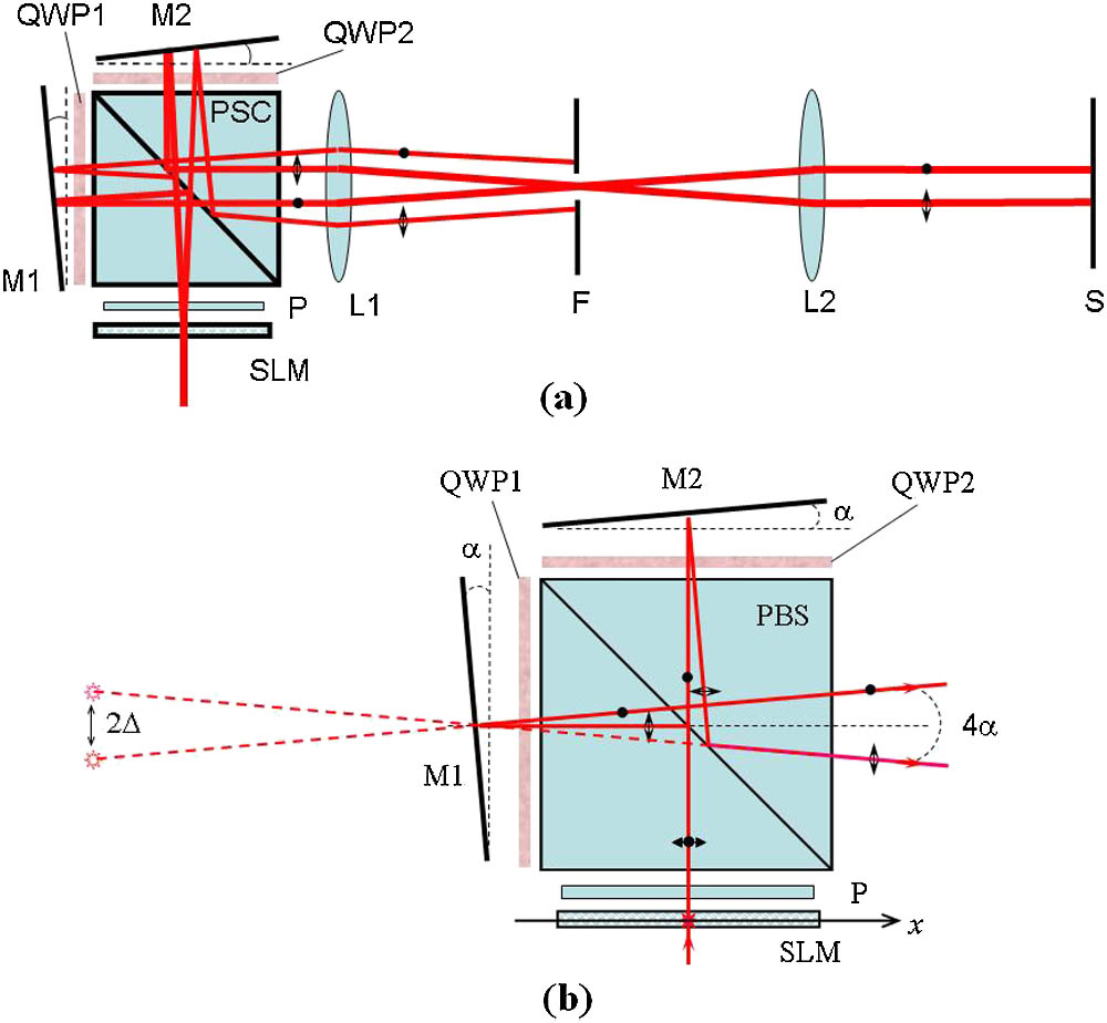
Figure 1(a) shows a schematic diagram of the improved setup. This setup mainly consists of three parts: (1) a transmission-type SLM for displaying computer-generated holograms (CGHs), (2) an APBS modulator formed by a thin-film 90° PSC, two quarter-wave plates (QWP1, QWP2) and two mirrors (M1, M2), and (3) a spatial filtering imaging system formed by two Fourier lenses (L1, L2) and an aperture filter F. The SLM is placed on the front focal plane of the Fourier lens L1. Its output polarizer P is orientated at 45° with respect to the vertical direction.
Figure 1.(a) Schematic diagram of the improved setup. (b) The optical path geometry through the APBS modulator.
For generating a vector beam with its two orthogonal polarization component functions of and in general, we first design a CGH according to the algorithm described below in which the component functions and are encoded in two different diffraction directions. Then the CGH is displayed on the SLM and illuminated by a linearly polarized beam. After passing through the APBS modulator, the reconstructed components and with orthogonal polarization states are reoriented to the same direction along the optical axis, which can pass through the aperture filter F and finally are combined into the desired vector beam on the output plane S of the setup.
For convenience of quantitative description of the principle, Fig. 1(b) further gives the detailed optical path geometry of the APBS. It can be seen that, if mirrors M1 and M2 are both slightly tilted by a small angle α as shown in Fig. 1(b), an input beam will be split into two orthogonal polarization components with a splitting angle of . In this sense, the APBS is equivalent to a small-angle birefringent beam splitter. So, supposing the transmittance distribution of the SLM is , the final output field on the output plane S without thinking about the influences of aperture filter F and the size of the lenses can be approximately expressed as where are the two orthogonal polarization components of the input beam; and are, respectively, the tilt factor and the shift amount introduced by the APBS (here, corresponds to the optical path length from the SLM plane to mirror M2 or M1). Compared with Eq. (2) in Ref. [39], we can see that the improved system shown in Fig. 1(a) has the same imaging properties or the same point spread function.
Therefore, we can design the CGH for the generation of the desired vector beams according to the algorithm described in Ref. [39]. For example, for creating the vector beam expressed by Eq. (1), the transmittance function of the CGH displayed on the SLM can be designed according to the formula or where and are two normalization constants for keeping within the range permitted by the adopted SLM.
Figure 2(a) gives an example of the CGH according to Eq. (3) for the generation of a vector vortex beam with different topological charges of its two orthogonal polarization components. Figure 2(b) shows the spatial frequency of the CGH shown in Fig. 2(a), while Fig. 2(c) presents the intensity distribution on the back focal plane of the lens L1 in Fig. 1(a) when the CGH is displayed on the SLM and illuminated by a plane beam. In Figs. 2(b) and 2(c), , is the focal length of lens L1; and are, respectively, the Fourier transform of the components and . From Fig. 2(c), it can be seen that if we set the aperture radius of the aperture filter F to equal to or less than and locate the filter aperture at the position marked by a red dotted circle in Fig. 2(c), all the unexpected terms for that purpose can be blocked and thus the field passing through the aperture filter is exactly the vector beam with the designed orthogonal polarization components of and .
Figure 2.(a) Example of the CGHs designed according to Eq. (3); (b) the spatial frequency of the CGH; (c) the intensity distribution on the back focal plane of the lens L1 when the CGH is displayed on the SLM of the system.
For demonstration of the improved system described above in experiments, we established the experimental setup in which the input beam comes from an ultrashort pulse laser with a wavelength of 532 nm and a pulse duration of 30 ps. The SLM is a transmission-type liquid crystal SLM with pixels and an pixel size. The APBS modulator is formed by an thin-film 90° PSC with an extinction ratio of , two multi-order quartz wave plates, and two protected aluminum front-surface mirrors. The focal lengths of the adopted Fourier lenses L1 and L2 are, respectively, 300 and 180 mm. The optical distance from the SLM plane to the mirrors is set to about 98 mm. A ccording to Eqs. (2) and (3), the reference spatial frequency of the CGH should satisfy the condition of , while the value of should be equal to or smaller than because of the discrete diffraction limit of the SLM used in the experiments (where the pixel size of the SLM is expressed by the sign ). So the tilt angle of the mirrors should be smaller than about 0.28°. In the examples of the experiments shown below, the tilt angle of the mirrors is set to be about 0.2°.
A typical type of vector beams is the cylindrically symmetric vector beams, which can be expressed as where , are the polar coordinates of the input plane, that is, and ; the integers and correspond, respectively, to the topological charge and radial index of the beam. In our experiments, we first designed some CGHs for the generation of cylindrically symmetric vector beams by substituting and with different parameters of into Eq. (4), and then displayed the CGHs on the SLM, as shown in Fig. 1. The intensity distribution of the output vector beams are recorded by an image sensor located at the output plane of the system. For detecting the polarization properties of the output vector beams, a polarization analyzer was inserted between the lens L2 and the image sensor.
Figures 3(a)–3(c) show the experimental results when parameter is taken as , and , respectively. The arrows at the upper right corners of all the sub pictures in Fig. 3 correspond to the orientation of the polarization analyzer located in front of the imaging sensor. According to the extinction distributions of the recorded intensity distributions, when the polarization analyzer is rotated to different orientations we can see that the output vector beams corresponding to the first two [Figs. 3(a) and 3(b)] are, respectively, radially polarized and azimuthally polarized, while the third case [Fig. 3(c)] belongs to the cylindrically symmetric vector beam with four Archimedes spiral extinction lines that are consistent with the theoretical predictions with and . These experimental results demonstrated that our designed vector beams are successfully generated in the output plane of the system.
Figure 3.Example of the experimental results when the parameter is taken as (a) , (b) , and (c) , respectively. The arrows in the upper right corners of the subpictures correspond to the orientation of the polarization analyzer located in front of the imaging sensor.
To further confirm the independent imaging ability in the two orthogonal polarization states, Figs. 4 and 5 give an experimental example of the polarization-selective encoding and imaging based on the system. Figure 4 shows a CGH designed according to Eq. (3) when the component functions and are taken as two completely different patterns, one the Chinese Dragon–Phoenix pattern and the other the Double Happiness pattern. Figure 5 shows the output images of the system when the CGH shown in Fig. 4 was displayed on the SLM and the polarization analyzer was rotated to different orientations. It can be seen that we get only the Double Happiness pattern when the analyzer was oriented at 0 (vertical direction); when the analyzer was rotated to 45° (or ), both the Double Happiness and the Dragon–Phoenix were seen, while when the analyzer was further rotated to 90°, only the Dragon–Phoenix pattern remained, as expected.
Figure 4.Example of the CGHs designed according to Eq. (3) using two completely different patterns and .
Figure 5.Output images of the system when the CGH shown in Fig. 4 was displayed on the SLM and the polarization analyzer was rotated to different orientations. The arrows in the upper right corners of the sub pictures correspond to the orientation of the polarization analyzer located in front of the imaging sensor.
In conclusion, our theoretical analysis and the experimental results demonstrate that the improved system described above is feasible for the generation of arbitrary vector beams. The main advantage of this system is that a single SLM and an angle-adjustable thin-film PSC modulator are adopted. Compared with the system using a BBS with a nonadjustable splitting angle, the polarization splitting angle in the improved system can be adjusted by slightly rotating the related mirrors as shown in Fig. 1 and is wavelength-insensitive due to the use of a broadband thin-film PSC, which will bring some more convenience when different wavelengths and different pixel sizes of SLMs are involved. We also demonstrate that the system possesses a good polarization-selective imaging ability. The system provides two independent polarization encoding and imaging channels, and the point spread functions corresponding to the two imaging channels could be controlled by the SLM so different output images with different polarization states could be obtained and processed. It should be noted that, because the SLM used in our experiments is an amplitude-type SLM, the CGH is encoded into a modified off-axis interference-type hologramand the energy efficiency is low. If a phase-only SLM is adopted and the CGH described by Eq. (3) is converted into a blazed phase-only CGH, the utility efficiency of the system could be greatly improved.
Yiyan Xie, Yang Yang, Lu Han, Qingyang Yue, Chengshan Guo. Generation of arbitrary vector beams based on a single spatial light modulator and a thin-film polarization splitting cubic[J]. Chinese Optics Letters, 2016, 14(12): 122601