
S. Z. Yi, J. Q. Dong, L. Jiang, Q. S. Huang, E. F. Guo, Wang Z. S.. Simultaneous high-resolution x-ray backlighting and self-emission imaging for laser-produced plasma diagnostics using a two-energy multilayer Kirkpatrick–Baez microscope[J]. Matter and Radiation at Extremes, 2022, 7(1): 015902
- Matter and Radiation at Extremes
- Vol. 7, Issue 1, 015902 (2022)
Abstract
High-resolution x-ray imaging is an essential diagnostic tool for determining the state of a plasma and its evolution, especially for the small-sized dense plasmas that occur in inertial-confinement fusion (ICF) and high-energy-density physics (HEDP).1 This type of imaging can be divided into self-emission imaging and backlit imaging. Backlighting imploding capsules with x-rays emitted from another backlit target can offer direct measurement of compression shape and shell distortion, while self-emission imaging can delineate useful signatures related to hot cores.2–4
The Kirkpatrick–Baez (KB) microscope and spherical crystal are two pieces of diagnostic equipment that are widely used to obtain high spatial resolution. The spatial resolution of the KB microscope can reach 3–5 µm,5 which is slightly better than that of a spherical crystal. Bent-crystal imaging does have the advantage of monochromaticity.6 However, a certain spectral resolution can still be achieved with the KB microscope if a multilayer film structure is coated onto the reflector surface. An additional advantage of the KB microscope is that it is easier to design a multichannel form than when using a bent crystal with nearly the same observation angle.7–9
In principle, a given type of x-ray imaging optics can only obtain diagnostic data of one kind, namely, either backlit or self-emission images. For example, Marshall et al.10 and Yi et al.11 independently developed 16-channel KB microscopes with two different optical structures and were thereby able to obtain high-resolution self-emission x-rays images of imploding targets at 16 transients. Sawada et al.12 developed a two-color monochromatic Kα-crystal imaging method for x-ray backlighting of a high-density plasma with a broader areal-density (ρR) range than that achievable with just a single backlighter. Generally, it is necessary to conduct measurements several times along the same observational axis using different diagnostic equipment to obtain the respective self-emission and backlighting signals. In this case, the variation of laser energy and the drive asymmetry between multiple shots will induce random differences in the measurement signal. These are difficult to correct and therefore have a serious impact on the accuracy of subsequent numerical simulations, especially for directly driven experiments.
In this paper, we develop a diagnostic method that can simultaneously observe self-emission and backlit images of imploded targets along nearly a single line of sight. This method can put the two types of diagnostic data in the same dimension for comparative analysis to improve the accuracy of simulation of electron temperature and areal density, bringing great benefits to numerical simulations.
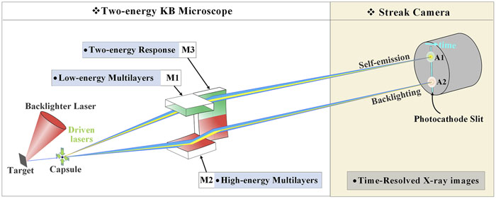
To allow simultaneous observation of the self-emission and backlit images of imploded targets, the method adopted should have three functions: x-ray imaging, spectral response, and time resolution. Of these, the time resolution of the imploded capsule can be recorded by a streak camera or a framing camera placed on the image plane. Multichannel x-ray optics are utilized to form multiple high-resolution images along the nearby observation axis, and by choosing the response energies of the beam splitters, it is possible to separate the backlight and self-emission signals into different imaging channels. To achieve these requirements, we propose a new diagnostic method based on a multilayer KB microscope with the optical structure shown in Fig. 1. From a geometric-imaging perspective, the KB microscope uses two perpendicular grazing-incidence mirrors to focus x-rays with high spatial resolution.4,7,8 It has the advantage of near-coaxial imaging in optical structure and can easily form a multichannel configuration. Artificial multilayers are coated onto the reflective surfaces of the KB mirrors, whose response energies are easier to control than those of natural crystals. Moreover, the temporal-evolution behavior of images can be recorded by a streak camera or framing camera placed on the image plane.
![]()
Figure 1.Schematic of simultaneous high-resolution x-ray backlighting and self-emission imaging by a two-channel multilayer KB microscope.
The microscope consists of two meridional multilayer mirrors (M1 and M2) arranged in opposite directions and a sagittal multilayer mirror (M3). In this arrangement, image points A1 and A2 are distributed on the image plane with the same magnification, making image analysis easier. Meanwhile, the interval between two images can be set to a specific value to couple with the photocathode-slit length of the streak camera or the microstrips of the frame camera. For a KB-type microscope, x-ray images can be considered to be independently formed in the tangential and sagittal directions. Therefore, there are no particular requirements on the size and shape of M3 to accommodate the tangential mirrors M1 and M2. If necessary, by increasing the number of multilayer mirrors, backlit and self-emission x-ray images of a laser plasma at more energy points can also be obtained.
The light path of the microscope in the meridional and sagittal planes is shown in Fig. 2. The imaging equation of each mirror in the tangential direction is
![]()
Figure 2.Optical arrangement of the two-energy KB microscope in the meridional and sagittal directions.
| Mirror | R (m) | d (mm) | θ (deg) | u (mm) | v (mm) | M | L (mm) |
|---|---|---|---|---|---|---|---|
| M1/M2 | 20.0 | 10.0 | 0.8462 | 160.0 | 1920.0 | 12.000 | 10.0 |
| M3 | 0.8945 | 170.0 | 1910.0 | 11.235 |
Table 1. Optical parameters of the KB microscope.
![]()
Figure 3.Spatial resolution of the KB microscope simulated by Zemax software.
Self-emission of an imploded target is mainly concentrated in the low-energy region, but higher-energy characteristic line radiation needs to be chosen for the x-ray backlighter to penetrate the high-density plasma. Thus, multilayers coated on two meridional mirrors were designed for low-energy self-emission (E1) and high-energy x-ray backlighting (E2). Based on Bragg diffraction, the multilayers, consisting of alternating bilayers of high- and low-Z materials, respond to x-rays with a high reflectivity.11 The sagittal mirror M3 has the same energy response, which is achieved by regional coating of the multilayers for E1 and E2 on two different mirror areas. For point A1 in the self-emission image, its response energy (E1) is consciously chosen to deviate from the range of the x-ray backlighter. The image point A2 responds to the x-ray backlighter energy (E2) and a narrow self-emission energy region, and its light intensity is mainly contributed by the backlighter; the self-emission intensity can be ignored in comparison with the backlighter. The spectral purity of the x-ray backlighter image can be further improved by placing Be, Al, and Ti filters in the optical path to filter out any x-rays with energies below 2.5 keV. Furthermore, the focal position of the x-ray backlighter was adjusted to deviate from the optical axis of self-emission imaging, thus effectively avoiding the interference of the x-ray backlighter with the self-emission signal.
The spectral responses of the microscope to x-ray backlighting and self-emission imaging are shown in Fig. 4. All multilayers for physical experiments were deposited onto ultrapolished silica substrates via a DC magnetron-sputtering system. Before fabrication of the multilayers for physical experiments, additional W/C multilayers working at 8.05 keV (Cu Kα line) were deposited onto the substrates in advance, to allow the microscope to be precisely aligned and assembled in air using a common copper x-ray tube. The bottom W/C multilayers do not reduce the x-ray throughput in physics experiments; furthermore, it is assumed that the spectral intensity of self-emission undergoes exponential decay and that the influence of 8.05 keV x-rays on the low-energy self-emission image is negligible.
![]()
Figure 4.Spectral response of the KB microscope for x-ray backlighting and self-emission imaging.
The microscope can be flexibly used in practical applications by energy selection with different filters, and the self-emission and backlit-imaging channels can be switched to meet different requirements. For example, when the areal density is low or the backlight driving-laser intensity is limited, E2 can be used as the backlighting channel, and an Mo target can be used as an x-ray backlighter (2.6–2.7 keV), as described in this paper. When the areal density is higher or the driving-laser intensity is sufficiently strong, E1 can be used as the backlighting channel, and the Sc target can be used as the x-ray backlighter (about 4.3 keV).
As shown in Fig. 3, owing to serious off-axis aberration, the spatial resolution of the KB microscope decreases markedly with deviation from the central FOV. In the application described in this paper, all three mirrors had to be accurately aligned for the central FOVs (with best spatial resolution) of the two imaging channels to coincide at the same target position in order to obtain a spatial resolution better than 5 µm. Moreover, the two imaging positions also had to be accurately indicated to ensure that the photocathode of the streak camera intercepted the desired local area, usually a certain diameter line. On the basis of the above considerations, three key technical problems had to be solved in microscope development: mirror assembly, off-line experiments, and on-line alignment.
First, we put two mirrors in the meridional direction (M1 and M2) against a precise glass prism whose specific size and conical angle ensured accuracy in the relative spatial positions of the two mirrors. Second, the best object–image relationship of the KB objective was found through an offline x-ray imaging experiment. As a kind of grazing x-ray optics with small numerical aperture, a KB microscope must use an area backlighter to illuminate the whole capsule, and the backlighter size determines the effective illuminated FOVs. For imaging of an object point, such as point A in Fig. 2, the upper and lower edges of the mirror surface can be illuminated by the backlighter, and its spatial resolution depends mainly on the structural parameters of the KB microscope listed in Table I. In addition, the reflective imaging of a KB microscope can be considered to be achromatic, and so spectral changes have little effect on spatial resolution, although there is a slight diffraction effect. In general, the performances of a KB microscope under real experimental conditions can be objectively evaluated by offline x-ray imaging experiments.
In particular, we used a large-focus copper x-ray tube to illuminate a 600-mesh gold grid with a linewidth of about 5–6 µm. The focal spot of the x-ray tube in the direction perpendicular to the optical axis was about 600 µm, equivalent to the capsule diameter. A 120 µm hole punctured in the grid served as a positional reference from the object to the x-ray image. A phosphor x-ray charge-coupled device (CCD) camera (VHR-11M, Photonic Science) with 4000 × 2667 pixels and a 9.0 × 9.0 µm2 pixel size was placed on the image plane. Two alphabet grids with letters A–Z were also fixed in front of the x-ray CCD as a visible reference. By adjusting the two grids with the translational stages, their centers were made to coincide with the respective reference holes of the two x-ray images. Figure 5(a) shows the final imaging results of the two channels after exposure times of 10 min. The distance between the centers of the two alphabet grids (i.e., the interval L between two images) was about 10.9 mm, thereby ensuring that the two images were within the length range of a 15 mm photocathode. As can be seen from Fig. 5(a), the gold grid with a linewidth of only 5–6 µm was clearly acquired by the objective in the whole effective FOVs. By comparing the grid period after imaging with the results measured by an SEM, the magnifications of M1 and M2 were found to be about 11.8 times in the imaging direction of the streak camera, whereas the magnification of M3 was about 11.1 times.
![]()
Figure 5.Results of evaluation of spatial resolution for a 600-mesh Au grid backlit by a copper x-ray tube.
The experimental resolution could be further measured by the intensity profiles taken along images in the vertical or horizontal directions. Specifically, the spatial resolution of M1 and M2 could be calibrated by the intensity distributions in the vertical direction shown in Figs. 5(b) and 5(d), respectively. According to the resolution criterion of 10%–90% rise distance, corresponding to the distance between 10% and 90% of the maximum intensity,7 the spatial resolutions of M1 and M2 are plotted in Figs. 5(c) and 5(e), respectively. They are better than 5 µm within FOVs of ±100 µm, and are consistent with the Zemax simulation results.
In addition, the spatial resolution of M3 could also be calibrated by the intensity distribution in the horizontal direction of A1 or A2, whose value is similar to those shown in Fig. 5. Actually, as shown in Fig. 2, the vertical and horizontal directions correspond to the photocathode length and width of the streak camera, i.e., the imaging and time scanning directions of the microscope, respectively. In the horizontal direction, the streak camera only intercepted a narrow band of spatial information, about 7.2 µm, which converts to an object FOV of 80 µm at the photocathode length and a magnification of 11.1 times.
A positioning ball with a diameter of 500 µm was then rigidly connected with the objective to accurately indicate the best object position (i.e., the reference hole in Fig. 5). A visible-light CCD was also rigidly connected with the objective, and the central coordinates of the alphabet grid in visible-light CCD imaging were also recorded as a reference for on-line alignment of the streak camera.
Finally, the microscope was used for backlit and self-emission imaging of imploding capsules at the SG-III prototype laser facility.13 During on-line alignment, the positioning ball was adjusted to the position of the target center. Under observation with the visible-light CCD, the slit of the streak camera along the diameter direction of the target perpendicular to the equatorial plane was adjusted to coincide with the position calibrated by the coordinates of the alphabet grid.
The capsules, filled with D2 fuel at 15 atm pressure, had an inner diameter of 380 µm, a 2.5 µm glass inner shell, and a 9 µm C8H8 ablator. Eight synchronized laser beams (1 ns, 3ω, 200 J) smoothed by a continuous-phase plate (CPP) with an oval focal spot of 350 × 500 µm2 directly illuminated eight quadrants of the target at 45° angles to the polar axis. The ninth laser beam (3 ns, 3ω, 2700 J), which was smoothed by a CPP with a 500 × 550 µm2 rectangular focal spot, was used to irradiate the Mo target to produce 2.6–2.7 keV x-ray backlighting. To cover the whole implosion process, the beginning of the ninth laser beam was set 200 ps earlier than eight driving laser beams.
Under direct irradiation by the eight laser beams, a convergent shock was produced and propagated into the D2 fuel. Then, the shell was gradually compressed and shrank. When the shock met and rebounded at the center of the capsule, the temperature rose in the fuel, a hotspot was produced, and x-rays were emitted. These processes were recorded well by this imaging method. The low-energy self-emission (E1) and high-energy backlit images (E2) of the imploding capsule were formed by the microscope with sufficient brightness and then recorded by the streak camera with a temporal resolution of about 25 ps, as shown in Fig. 6.
![]()
Figure 6.Simultaneous backlighting and self-emission x-ray imaging of a direct drive CH shell target, taken by the KB microscope and streak camera at the SG-III prototype laser facility.
It can be seen from Fig. 6 that the self-emission signal in the E2 channel was suppressed well and that the outer-boundary trajectory of the capsule could be extracted and the implosion speed calculated. The backlight signal in the E1 channel was also suppressed to a very low level, and important information such as the evolution of the hotspot temperature could be evaluated. Because of limitations on the number of laser beams, trajectory inconsistency between the upper and lower boundaries (introduced by irradiation uniformity) can be seen in the backlit image in Fig. 6. The trajectory in Fig. 7 was extracted from the upper half of the backlit image in Fig. 6, and the history of the hotspot emission intensity was extracted from the 20 central vertical pixels in the self-emission image presented in Fig. 6. The beginning of the backlighting x-rays can be decided from Fig. 6, and was set as the initial moment of time in Fig. 7. It can be seen from Fig. 7 that the shock met at the center at about 0.77 ns and that the hotspot reached maximum temperature at about 0.82 ns, before the capsule was most compressed at 0.90 ns.
![]()
Figure 7.Outer-boundary trajectory (red line) of the capsule shell extracted from the upper half of the backlit image in
To summarize, a high-resolution diagnostic method for simultaneous x-ray-backlit and self-emission imaging has been developed to comprehensively analyze different types of diagnostic data in a single shot to improve the accuracy of simulations of laser-produced plasmas. This method utilizes a two-channel KB microscope with multilayer coatings for high-energy backlight imaging and low-energy self-emission imaging diagnostics. A high-resolution image with a spatial resolution better than 5 µm was obtained in the laboratory. An integrated object–image indication method based on a positioning ball and a visible-light CCD was used for precise microscopic alignment. Experimental imaging of an imploding capsule in the SG-III prototype laser facility has demonstrated the feasibility of the proposed method.
Acknowledgment. This work was supported by National MCF Energy R&D Program (Grant No. 2019YFE03080200), the National Natural Science Foundation of China (Grant No. 11805212), and the Fundamental Research Funds for the Central Universities (Grant No. 22120200405).
References
[1] S.Atzeni, J.Meyer-ter-Vehn. The Physics of Inertial Fusion: Beam Plasma Interaction, Hydrodynamics, Hot Dense Matter(2004).
[2] M. A.Barrios, M.Dayton, B.Haid, B. A.Hammel, D.Holunga, M. Hoppe, T.Kohut, O. L.Landen, A. G.MacPhee, L. A.Pickworth, S. P.Regan, H. F.Robey, M. B.Schneider, H. A.Scott, V. A.Smalyuk, C.Walters. Measurement of hydrodynamic growth near peak velocity in an inertial confinement fusion capsule implosion using a self-radiography technique. Phys. Rev. Lett., 117, 035001(2016).
[3] D.Batani, S.Baton, F. N.Beg, L.Fedeli, S.Hulin, L. C.Jarrott, A.Margarit, A.Morace, M.Nakai, M.Nakatsutsumi, P.Nicolai, N.Piovella, J. J.Santos, X.Vaisseau, L.Volpe, M. S.Wei. Development of x-ray radiography for high energy density physics. Phys. Plasmas, 21, 102712(2014).
[4] F. N.Beg, R.Betti, H.Chen, J.Delettrez, T.D?ppner, E. M.Giraldez, V. Y.Glebov, H.Habara, T.Iwawaki, L. C.Jarrott, M. H.Key, R. W.Luo, F. J.Marshall, C.McGuffey, H. S.McLean, C.Mileham, P. K.Patel, B.Qiao, J. J.Santos, H.Sawada, A. A.Solodov, R. B.Stephens, C.Stoeckl, W.Theobald, M. S.Wei, T.Yabuuchi. Visualizing fast electron energy transport into laser-compressed high-density fast-ignition targets. Nat. Phys., 12, 499-504(2016).
[5] A. V.Baez, P.Kirkpatrick. Formation of optical images by x-rays. J. Opt. Soc. Am., 38, 766-774(1948).
[6] T.Filkins, R.Jungquist, C.Mileham, N. R.Pereira, S. P.Regan, M. J.Shoup, C.Stoeckl, W.Theobald. Characterization of shaped Bragg crystal assemblies for narrowband x-ray imaging. Rev. Sci. Instrum., 89, 10G124(2018).
[7] Z. H.Fang, S. Z.Fu, P. F.He, W. B.Li, B. Z.Mu, W.Wang, X.Wang, Z. S.Wang, S. Z.Yi, J. T.Zhu. Time-resolved multispectral X-ray imaging with multi-channel Kirkpatrick-Baez microscope for plasma diagnostics at Shenguang-II laser facility. Chin. Opt. Lett., 12, 083401(2014).
[8] Y. Q.Gu, Q. S.Huang, Z. S.Wang, L.Wei, S. Z.Yi, F.Zhang. High-resolution X-ray flash radiography of Ti characteristic lines with multilayer Kirkpatrick–Baez microscope at the Shenguang-II Update laser facility. High Power Laser Sci. Eng., 9, e42(2021).
[9] Z. S.Fang, Q. S.Huang, B. Z.Mu, Z. S.Wang, S. Z.Yi, Z.Zhang, Z.Zhang. Eight-channel Kirkpatrick–Baez microscope for multiframe x-ray imaging diagnostics in laser plasma experiments. Rev. Sci. Instrum, 87, 103501(2016).
[10] R. E.Bahr, V. Yu.Glebov, V. N.Goncharov, F. J.Marshall, B.Peng, S. P.Regan, T. C.Sangster, C.Stoeckl. A framed, 16-image Kirkpatrick–Baez x-ray microscope. Rev. Sci. Instrum., 88, 093702(2017).
[11] L.Cao, Y.Gu, Q.Huang, D.Liu, Z.Wang, L.Wei, S.Yi, Z.Zhang, Z.Zhang. Tandem Kirkpatrick–Baez microscope with sixteen channels for high-resolution laser-plasma diagnostics. Rev. Sci. Instrum., 89, 036105(2018).
[12] Y.Arikawa, F. N.Beg, S.Fujioka, S.Lee, H.Nagatomo, H.Nishimura, N.Ohnishi, P. K.Patel, F.Pérez, H.Sawada, K.Shigemori, T.Shiroto, A.Sunahara, W.Theobald, T.Ueda. Flash Kα radiography of laser-driven solid sphere compression for fast ignition. Appl. Phys. Lett., 108, 254101(2016).
[13] Y. H.Chen, F. P.Condamine, Y. K.Ding, T.Gong, Z. Y.Guan, L.Hudec, W. Y.Huo, S. E.Jiang, N.Jourdain, M.Kr?s, K.Lan, J.Li, S. W.Li, Y. L.Li, Z. C.Li, J.Limpouch, R.Liska, X. M.Liu, Y. G.Liu, W.Nazarov, K. Q.Pan, X. S.Peng, G.Ren, O.Renner, T. M.Song, V. T.Tikhonchuk, F.Wang, S.Weber, T.Xu, D.Yang, J. M.Yang, B. H.Zhang, W.Zheng. Studies of laser-plasma interaction physics with low-density targets for direct-drive inertial confinement fusion on the Shenguang III prototype. Matter Radiat. Extremes, 6, 025902(2021).


Set citation alerts for the article
Please enter your email address

© Copyright 2018-2021 | Chinese Laser Press. All Rights Reserved 沪ICP备15018463号-20