Guodong Zhang, Guanghua Cheng, Manoj K. Bhuyan, Ciro D’Amico, Yishan Wang, Razvan Stoian. Ultrashort Bessel beam photoinscription of Bragg grating waveguides and their application as temperature sensors[J]. Photonics Research, 2019, 7(7): 806
Copy Citation Text
Ultrashort pulsed Bessel beams with intrinsic nondiffractive character and potential strong excitation confinement down to 100 nm can show a series of advantages over Gaussian beams in fabricating efficient Bragg grating waveguides (BGWs). In this work, we focus on parameter management for the inscription of efficient BGWs using the point-by-point method employing Bessel beams. Due to their high aspect ratio, the resulting one-dimensional void-like structures can section the waveguides and interact efficiently with the optical modes. Effective first-order BGWs with low birefringence can then be fabricated in bulk fused silica. By controlling the size and the relative location of grating voids via the Bessel pulse energy and scan velocities, the resonant behaviors of BGWs can be well regulated. A high value of 34 dB for 8 mm length is achieved. A simple predictive model for BGWs is proposed for analyzing the influences of processing parameters on the performance of BGWs. The technique permits multiplexing several gratings in the same waveguide. Up to eight grating traces were straightforwardly inscribed into the waveguide in a parallel-serial combined mode, forming the multiplex BGWs. As an application, the multiplex BGW sensor with two resonant peaks is proposed and fabricated for improving the reliability of temperature detection.
1. INTRODUCTION
The point-by-point (PbP) laser writing method using ultrashort laser pulses [1] is a recently emerged direct fabrication technique for fiber Bragg gratings (FBGs) that has attracted significant attention and has been applied for various optical systems such as optical networks, sensors, and fiber lasers [2–8]. The tightly focused laser pulse, with intrinsic high laser intensity, allows creation of localized refractive index modifications (positive or negative) from structural and morphology changes inside the fiber component via nonlinear photoionization mechanisms [9,10]. At high enough energy levels, the morphology change usually appears as a sub-micrometer-sized void centered in the laser irradiated region [11,12] surrounded by a narrow layer of compressed matter. Therefore, in this regime, small-period Bragg gratings can be directly inscribed into the fiber with strong and negative refractive index modulation [13]. In addition, the possibility of increasing the grating dimensions was explored by using laser filaments and nondiffractive beams inducing type II interactions [14,15]. The type II FBGs inscribed using the PbP method are proven to possess high temperature stability, indicating better thermal resistance than type I FBGs [10] in the application of temperature sensors. The flexibility of the PbP method via the writing strategy allows fabrication of various nonuniform PbP gratings, including phase-shifted, apodized, and superstructure gratings [16,17].
Recently, the PbP method was used to insert Bragg gratings into the laser-induced waveguides in bulk glasses, forming Bragg grating waveguides (BGWs) [18]. This generates integrated photonic devices with high mechanical stability. A recent review [19] summarizes the advances in creating PbP gratings and the achieved level of coupling in various materials and configurations. In 2006, Marshall et al. first demonstrated the creation of BGWs in fused silica by using a femtosecond pulsed laser with the PbP method [18]. The seconnd-order gratings working at about 1550 nm were inserted and extended over the 11 mm long waveguide. The grating coupling strength was about . This method was further applied to the fabrication of 3D integrated photonic chips in boro-aluminosilicate glass with the coupling strength of the inserted grating being measured to be about [3]. In addition, Zhang et al. modified the PbP method and created novel BGWs in borosilicate glass with only one laser scan [7]. The linear array of refractive index voxels acts as both the waveguide and Bragg grating, holding the propagation of light with bond stop characteristics. The corresponding grating coupling strength was about . To maximize the coupling strength of the PbP gratings in fused silica, waveguide bundles consisting of several parallel and overlapping waveguides were proposed, and the corresponding BGWs were measured to have a coupling strength of [20]. Summarizing various materials and configurations [19], the coupling levels of PbP gratings are in the range of for fused silica while mounting rapidly for other silicate glasses (a very high value of was measured for BGWs fabricated in Schott IOG-10 glass), thus showing strong material and geometry dependencies. With a focus on fused silica, here we explore strategies to increase these values as a necessary step for establishing highly compact and integrated photonic devices in fused silica glass.
In order to maximally improve the integration level, the fabrication of lower-order BGWs with strong coupling strength should be addressed. For the fabrication of lower-order BGWs, the ultrashort Gaussian beam usually needs to be tightly focused, forming a wavelength-scale laser focal spot. However, considering that the tightly focused laser has a short Rayleigh length, the transverse overlap [21] between the grating void and the guided mode is relatively small, and therefore the coupling strength. To handle this issue, we recently proposed to use a tightly focused Bessel beam to improve the grating coupling strength [22]. Focused Bessel beams, known to have an intense central core and sustained for a relatively long distance [23,24], can induce arrays of one-dimensional morphological features with sub-micrometer periods into the waveguide. Using tight focusing geometries or dispersion control, the features can become one-dimensional void-like structures with strong index contrast. Therefore, the transverse overlap between the grating void and the guided mode can be greatly improved. Highly efficient BGWs working at about 1550 nm with grating order ranging from 1st to 10th were fabricated in bulk fused silica, demonstrating the remarkable advantages of this Bessel PbP method. However, for precisely regulating the resonant behaviors of BGWs, intensive study on the influences of processing parameters on BGW performance is still of significant importance. In addition, it is also meaningful to explore the application of BGWs on photoelectric sensors.
Sign up for Photonics Research TOC. Get the latest issue of Photonics Research delivered right to you!Sign up now
In this work, an efficient first-order BGW is fabricated and optimized in fused silica by using a Bessel-based PbP method. The birefringence characteristics of BGWs in the resonant spectral transmission gap are measured and simulated. By controlling the Bessel pulse energy, the diameter of the grating void is well regulated. Considering a physical evaluation of the dependence of the grating void size on pulse energy, a predictive model for BGWs is constructed based on the coupled mode theory. The dependences of gratings properties, such as coupling strength, peak position, and bandwidth (full width at half-maximum) on the writing conditions are carefully discussed. Based on parameter management for grating fabrication, multiplex BGWs are fabricated with the insertion of up to eight grating traces with different resonance peaks. In addition, a BGW sensor with two resonant peaks is proposed and fabricated for improving the reliability of temperature detection.
2. EXPERIMENT
A. Fabrication of BGWs
A Yb:KGW medium ultrafast laser system (Pharos, Light Conversion) with tunable repetition rate and working at wavelength of 1030 nm is used as the laser source in the experiment. The pulse duration can be easily tuned from 190 fs to 10 ps. The sample, in the size of , used for inscribing BGWs is Corning 7980-5F fused silica. A high-precision air-bearing stage (Aerotech) is used to move the sample with a constant velocity during the irradiation of sequential ultrafast laser pulses [22].
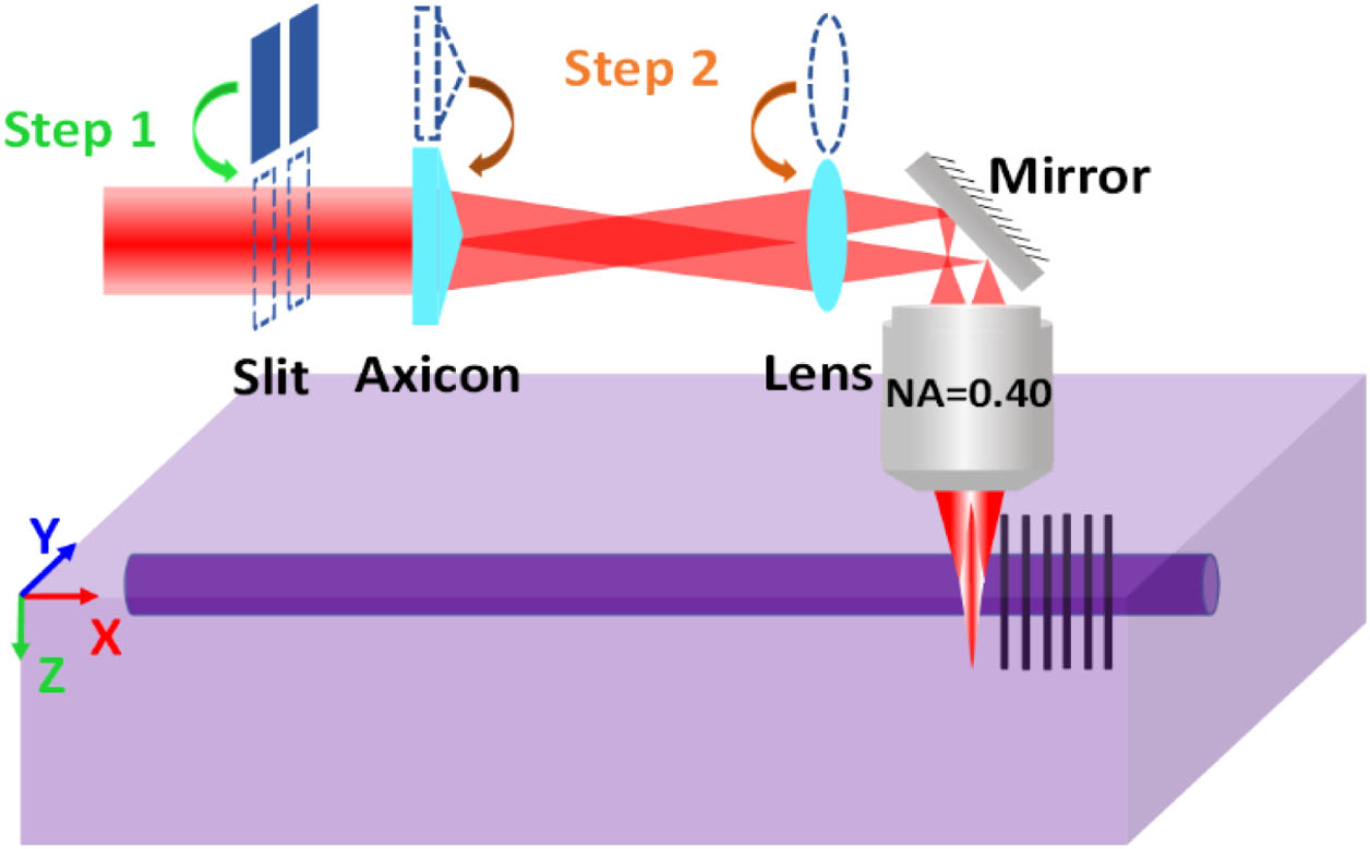
A microscope objective with a numerical aperture of 0.4 is used as the final focusing element as shown in Fig. 1. By utilizing the slit shaping method [25], a straight waveguide (type I) is directly volume-inscribed into the glass sample by 190 fs, 100 kHz, 1.2 μJ laser pulses. The slit width is about 700 μm, while the translation speed is fixed at 0.5 mm/s. In order to confine the size of the guided mode and hence improve the transversal overlap between the gratings void and the guided mode, the waveguide for BGWs is finally fabricated by bundling four parallel slightly overlapping traces together. The final waveguide supporting single-mode transmission has a length of 20 mm. Then the axicon and optical lens are inserted into the irradiation path, forming a imaging system. The zero-order Bessel beam produced by the axicon is demagnified and imaged into the laser-inscribed waveguide. The effective half-cone angle of the Bessel beam inside the fused silica is about 15°, and the calculated core diameter is about 0.9 μm. The pulse duration of the Bessel beam is fixed at 1 ps, which allows us to produce one-dimensional nanovoids with a length of 40 μm at pulse energy of 2.2 μJ. The period of the grating voids can be regulated by the repetition rate of the laser source and the speed of the translation stage.
Figure 1.Schematic fabrication setup for BGWs: the waveguide is first photoinscribed by using femtosecond Gaussian pulses in a slit shaping method, then the picosecond Bessel pulses are generated by using an insertable system with an axicon element to induce grating voids inside the waveguide along the -axis direction.
The index and morphology change of BWGs are characterized by the positive phase-contrast microscopy (PCM), focused ion beam etching (FIB), and scanning electron microscopy (SEM). The resonant transmission responses of BGWs were measured by injecting large-band near-infrared radiation from an amplified spontaneous emission (ASE) source (Idil) and recording the result in transmission with an optical spectrum analyzer (Yogokawa). A self-assembled system is used to connect and bond the single-mode fiber and BGW together to make a temperature sensor. The characterization of the thermal responses of the BGW sensor will be described in detail in the following section.
3. EXPERIMENTAL RESULTS
A. Characterization of First-Order BGWs
The first-order Bragg gratings (grating period 0.536 μm) with a resonant peak at 1550 nm are inserted into the waveguides by using a picosecond Bessel beam with Bessel pulse energy ranging from 1.6 to 2.0 μJ. The grating trace along the waveguides has a length of 10 mm, adding propagation losses in the range of 2 dB/cm. Figure 2(a) shows the resonant spectral transmission of BGWs at a wavelength of about 1550 nm. Obviously, the width and intensity of the resonant peak increase with the increase of pulse energies. When the pulse energy is above 1.8 μJ, the resonance intensity could be more than 40 dB. The coupling strength could rise up to at a pulse energy of 1.9 μJ ( resonance), deriving from [26], where is the grating length, is the reflectivity of the Bragg grating, and . This value is higher than the typical values reported () by using the Gaussian PbP method [27]. Note that by optimizing the writing with precise sequences of pulse bursts, a strong coupling strength can be achieved (). This value can be exceeded in other glasses ( Schott IOG-10 silicate) [19], being sensitive to the physical transformation scenario. The resonance peak of BGWs corresponding to a pulse energy of 2.0 μJ exhibits the broadest bandwidth with a flat-top profile, which is quite different from typical resonant peaks. Such resonant behavior is more like that of the chirped BGWs reported in fused silica [28]. We attribute this to the overlap or interaction effects between adjacent Bessel voids, which would cause perturbation to the grating period. Therefore, it appears not beneficial to keep increasing the Bessel pulse energy to improve the coupling strength. In addition, an apparent transmission loss on the shorter-wavelength side of the resonance is observed due to the coupling into the radiation mode, and this transmission loss increases with the increase of pulse energy.
Figure 2.(a) Resonant spectral transmission of first-order BGWs inscribed with different Bessel pulse energies. (b) Resonant spectral transmission of first order BGWs inscribed with pulse energy of 1.6 μJ upon injection with two orthogonal linear polarizations. The insets show the energy flux profiles for the parallel-polarized (left) and perpendicular-polarized (right) modes.
The birefringence of first-order BGWs (1.6 μJ) is studied through experiment and simulation. The resonant spectral transmission of BGWs for linearly polarized injection is shown in Fig. 2(b). The curves in red and blue correspond to the polarized injection aligned parallel and perpendicular to the Bessel trace, respectively. The resonance splitting is only about 16 pm and indicates a weak birefringence existing in the BGWs. The birefringence is further estimated to be about , deriving from [29], where is the grating period. The effective index of the parallel polarized mode () has a smaller value compared with that of the perpendicular polarized mode (), which is consistent with the characteristics of type II BGWs and the simulation results described below.
The birefringence of BGWs was further simulated by using a finite-element analysis tool. The insets in Fig. 2(b) show the cross-section diagram of BGWs and mode field profiles in two different polarization states. Based on the characterization of the near-field mode and structure of BGWs, an equivalent single-core structure was used in the model with the following parameters: core radius of 6 μm, core refractive index of 1.44787 at 1550 nm, and cladding refractive index of 1.44400 at 1550 nm. The grating void length is characterized to be about 40 μm, while its diameter is estimated to be 70 nm according to the varying trend in Fig. 3. For the mode calculation, the index modulation is treated as invariant as reported by Nemanja et al.[29]. The refractive index of the void is assumed to be equal to 1. For a duty cycle, the averaged index change within the void zone could be approximated as where and are the center coordinates of the void (i.e., grating offset value) relative to the center of the waveguide cross section. The results show that the effective indices of the guided modes for parallel and perpendicular polarization are 1.44575 and 1.44578, respectively. The birefringence of BGWs would be about , which is in the same order as the experiment value.
Figure 3.(a) Longitudinal section of the grating void (2.8 μJ) after material removal by FIB. (b) Cross sections of the post-polished grating voids induced by picosecond Bessel beam with different pulse energies. (c) Dependence of the voids’ diameters and surrounding condensed region on pulse energies.
B. Dependence of Grating Void Size on Bessel Pulse Energy
The morphologies of grating voids corresponding to different Bessel pulse energies were characterized as shown in Fig. 3. The results in Fig. 3(a) show the longitudinal section of the grating void for Bessel pulse energy of 2.8 μJ after material removed by FIB. The careful FIB etching procedure allowed us to minimize the damage produced onto the one-dimensional Bessel void. As shown in the image, the void possesses a quasi-invariable diameter of 163 nm along the laser beam, indicating the superiority of Bessel beams over Gaussian beams in extending the grating void length. The void wall is shown to have experienced a melting and re-solidification process. Figure 3(b) shows the SEM images of cross section of grating voids after the post-polishing process. It could be found that the typical Bessel void surrounded by a potentially densified region is formed inside the sample. The sizes of the nanovoid and the modified neighboring region were found to be related with Bessel pulse energy. We would note that some voids are blocked due to the glass debris during the polishing process.
The characterized sizes of the void and densified region under different Bessel pulse energies were concluded and shown as the data points in Fig. 3(c). With the increase of pulse energy, the diameters of the voids and surrounding densified regions increased monotonically. When the pulse energy is above 2.0 μJ, the diameter of the densified regions would be more than 0.5 μm. Considering that the period of the first-order Bragg grating is about 0.5 μm, an apparent inter-effect between adjacent grating voids would occur, influencing the resonant behavior of the BGWs. Similarly, when the pulse energy is close to 5.0 μJ, inter-effect between adjacent grating voids will be apparent for the seconnd-order BGWs with period of about 1 μm.
For discussing the relationship between void size and pulse energy, a simple dimensional model relating the structure to the shape of the beam was proposed. We note that this is a simplified though intuitive approach that does not consider nonlinear effects on the beam size nor the formation mechanisms presumably related to cavitation due to strong gradients [23]. More physical dependencies were proposed in Ref. [12] based on shock generation, but a simpler eye-guiding model without consideration of the complexity of ionization and matter transformation could be a first estimative trial. We consider, similarly to the surfaces in Ref. [30], that modification occurs when local fluence in a propagation plane exceeds a transformation threshold. This implies a quasi-instantaneous transformation (for example, to the gas phase), without implying further dimensional evolution of the modification (for example, expansion) at a given absorbed volume energy density, or it implicitly assumes that potential mechanical expansion is small compared to the beam spot sizes. The peak fluence of a Bessel beam in the nondiffractive region takes the form of where is the energy crossing the respective transverse plane in the core section proportional to the incident pulse energy, is the section radius in the core, and is the initial waist of the Gauss beam before the axicon [31]. For simplicity, we fit the Bessel section on the core with a Gauss form. Neglecting nonlinearities in propagation, self-focusing, and other facts, the void is considered to be induced whenever the local fluence exceeds a threshold ; where is the void radius and is the order of absorption, typically 7 or 8 for fused silica. Consequently, the relationship between void diameter and pulse energy could be obtained as The black curve as shown in Fig. 3(c) presents the simulated results by using Eq. (5). The is taken to be 421 nm in the curve fitting, which is slightly less than the calculated core radius of a Bessel beam, while the absorption order and pulse energy threshold are assigned to be 7 and 1.45 μJ, respectively. Considering the characterized resonant behaviors of gratings [see Fig. 4(a)], the critical pulse energy for inducing a Bessel void (1.45 μJ) is a reasonable value. According to Eq. (5), the void diameter corresponding to pulse energy of 1.6 μJ is estimated to be about 70 nm.
Figure 4.(a) Measured resonant spectra of BGWs with grating segment length of 8 mm. The picosecond Bessel pulses used for inducing grating voids range from 1.5 to 5.0 μJ. (b) Measured and modelled effective refractive index change of BGWs fabricated with different Bessel pulse energies. The inset is the enlarged version. (c) Measured and modelled coupling strength of BGWs fabricated with different Bessel pulse energies. (d) Measured and modelled bandwidth of resonance peak of BGWs fabricated with different Bessel pulse energies.
C. Dependence of Grating Void Size on Bessel Pulse Energy
Aiming to quantitatively analyze the influences of processing parameters on the resonant behaviors of BGWs, a predictive model was constructed in this section. In spite of the strong index change within the Bessel trace, the index modulation with respect to the waveguide core is still of a small value; the processed samples in our work are in a weak-to-strong-gratings transitional regime. Based on the coupled-mode theory [26,32], the transverse coupling strength has the following simple expression: where is the effective refractive index modulation due to the grating traces. The effective index modulation is known to be related to both the index change within the grating trace and the overlap factor between the grating void and mode field. Since the index change on the grating trace varies periodically, it is not conducive to calculate. To simplify the calculations, the index change on the grating trace is treated as a -invariant expressed by Eqs. (1) and (2). Therefore, the effective refractive index modulation would take the following form: Considering that the guided mode takes a transverse Gaussian distribution with a diameter of , Eq. (7) would be transformed into the following form after normalizing the mode field: Since the grating void is long enough for running through the cross section of waveguide, the slight offset of the void position in the direction is considered to have negligible influence on the and therefore the resonant behavior of BGWs. The in Eq. (1) could be treated as for our experiment. On the contrary, the grating offset in the direction would induce apparent influence on the and the resonant behavior of BGWs. Since the diameter of void is significantly smaller than that of the waveguide, the intensity of the mode field within the void region is approximate to be constant in the direction. Plugging Eqs. (1) and (2) into Eq. (8), the expression of the effective index modulation would be transformed as follows: The item could be understood as the weight of the averaged index change, which is determined by the grating offset () and void diameter (). For a certain Bessel pulse energy, i.e., void diameter, the is only related with the grating offset in the direction. Since the sample in our work remains in a weak-to-strong-gratings transitional regime, the bandwidth of the resonant peak takes the following form: where and are, respectively, the resonant peak and effective refractive index of BGWs and is the length of grating segment.
D. Regulation of Resonant Behaviors through Bessel Pulsed Laser Irradiation
The resonant behaviors of third-order BGWs fabricated with Bessel pulse energy ranging from 1.5 to 5.0 μJ were characterized as shown in Fig. 4(a). The grating segments along the waveguide have a length of 8 mm, which increases the propagation loss by 2 dB/cm. This propagation loss would slightly decrease with the decrease of Bessel pulse energy. It can be found that the intensities, central positions, and FWHMs of the resonant peaks could be regulated by Bessel pulse energy, i.e., grating void sizes.
From the central wavelength of the resonant peak, the effective refractive index of BGWs can be obtained, derived from the resonance relation . Therefore, the effective refractive index change due to the grating trace can be obtained through , where is the effective index of the initial waveguide at 1550 nm. The relationship between the effective refractive index change and Bessel pulse energy is shown in Fig. 4(b). The inset presents the enlarged version. Due to the type II index modulation, the effective index change is demonstrated to be of a negative value. This value decreases with the increase of pulse energy as the void’s section increases. The maximum absolute value of effective index change is at Bessel pulse energy of 5.0 μJ. Since the grating void is inserted into the center of the waveguide cross section, the in Eq. (9) is treated as 0. Therefore, the effective refractive index change should be only determined by the square of the void diameter, i.e., the natural logarithm of Bessel pulse energy. The blue curve presents the simulation results from Eq. (9). It can be seen that there is an apparent deviation between the experimental and simulated results, and the deviation increases with the increase of pulse energy. This is mainly because the influences of the probable densification around the void and the laser-induced stress are neglected in the initial model.
To refine the model, the effective index changes due to densification should be added into Eq. (9). Therefore, we first need to get the dependence of the size and index change of the densified region on Bessel pulse energy. For discussing the former, the mass conservation law was applied with consideration of the void formation inside the glass [12]. The material within the cylindrical void is thought to be pushed into the cylindrical shell, forming the densified region. Assuming the densified region is uniform and has a density of ( being the initial density), the diameters of void and densified region can be associated through the following equation: The red curve as shown in Fig. 3(c) presents the simulated results by using Eqs. (5) and (11). The factor is assigned as 1.094, which means the condensed material has a density 1.14 times higher than that of the initial material.
For evaluating the index change of the densification during the material mechanical evolution, the Clausius—Mossotti relation is used, where is the response coefficient of index change to the relative densification . By using the mass conversation law and Eq. (11), the expression of index change within the densified region would be obtained, taking the form of . Considering the weight factor of the averaged index change of the densification, Eq. (9) would be refined as where the constant is assigned as 0.383 [which comes from the fitting between Eq. (12) and the experiment value of in Fig. 4(b)]. This is a reasonable value and comparable to that of others’ work [33,34]. No changes in molecular polarizability are considered. Therefore, the effective refractive index change due to the densification increases with the increase of pulse energy ranging from 1.5 to 5.0 μJ. The red curve presents the simulation result by using Eqs. (6) and (12), which is well fitted with experimental results. We note, however, that this model, though physically intuitive, treats the evolution in a simple manner, as phase transitions and mechanical expansion are not treated self-consistently in Eqs. (5) and (11). It nevertheless gives a guiding line in the index evolution.
Figure 4(c) shows the grating coupling strength obtained through the relation [26], in which is the reflectivity of BGWs inferred as the complement to the resonant spectral transmission. The red curve represents the simulation results. The coupling strength increases with the increase of pulse energy and reaches its maximum value of at pulse energy of 5.0 μJ. The results can be interpreted as below. With the increase of Bessel pulse energy, the diameter of the grating void increases, inducing the increase of the overlap factor between the mode field and grating void and hence the coupling strength. The results prove that the coupling strength could be well regulated by the void size through Bessel pulse energy.
The bandwidths of the resonant peaks corresponding to different pulse energies were measured as shown in Fig. 4(d). It is apparent that the bandwidth increases with the increase of Bessel pulse energy. The minimum bandwidth is about 130 pm at a Bessel pulse energy of 1.8 μJ. The maximum bandwidth could be up to 320 pm with Bessel pulse energy of 5.0 μJ. The simulation result by using Eq. (10) is shown as the red curve in Fig. 4(d). Although the experimental and simulated results have a similar variation trend, there is a large deviation between them. The simulated value is always smaller than the experimental value over the entire range. This artefact appears due to the fact that the grating voids are stable in period in the simulation. However, during the experiment, the perturbation of the grating period due to the processing platform or other uncertainty factors is inevitable, which would lower the resonance quality and increase the resonance bandwidth.
E. Regulation of Resonant Behaviors through Void Spatial Offset
Considering that the mode field has a Gaussian distribution, the grating offset with respect to the center of the waveguide would influence the overlap factor between the grating void and guided mode, and therefore it determines the resonant behaviors of BGWs. By controlling the translation stage, the grating offset in the direction () with respect to the waveguide center could be well regulated as shown in the diagram in Fig. 5(a). The third-order Bragg gratings written at 2.2 μJ were inserted into the waveguides with different offset values ranging from 0 to 11 μm. The grating segments have a fixed length of 10 mm. Figure 5(b) presents the top-view PCM images of the BGWs. The resonant responses of the BGWs to the grating offset are characterized as shown in Fig. 5(c). It is apparent that the intensities of the resonant peaks decrease with the increase of grating offset. In addition, the peak position appears red-shifted with the increase of the grating offset. For BGWs with a grating offset of , the intensity of the resonant peak is measured to be approximately 40 dB, and the corresponding coupling strength is . If we define the coupling strength at grating offset of 0 μm as , the grating coupling strength has an expression of , according to Eqs. (6) and (12). This means that the coupling strength decreases with the increase of grating offset. The simulation results are presented with the red curve in Fig. 5(d), which are well fitted with the experiment results. Since has a negative value in our work, the effective refractive index of BGWs will increase with the increase of grating offset, according to Eq. (6). This can reasonably explain the red-shift of resonant peak as shown in Fig. 5(c).
Figure 5.Bessel voids were inserted into the waveguide with different offsets relative to the center of the waveguide’s cross section. The pulse energy of the picosecond Bessel beam for inducing grating void was fixed at 2.2 μJ. (a) Diagram of the offset BGWs. (b) PCM top images of the spatially displaced BGWs. (c) Resonance spectra of third-order BGWs with different offset values. (d) Dependence of coupling strength on the offset value.
F. Fabrication of BGWs with Multiple Resonant Peaks
The flexibility of the PbP method and the spatial confinement of the Bessel trace down to 100 nm allow us to fabricate multiplexed BGWs. Based on parameter management for grating fabrication discussed above, up to eight grating traces with different resonance peaks were inserted into the 20 mm waveguide in a parallel-serial-combined form as demonstrated in the PCM images in Fig. 6. Each of the grating segments (Part 1 and Part 2) in serial is composed by four parallel grating traces with a fixed length of 9 mm. The separation between the parallel grating traces is about 1.5 μm. In order to make the resonance intensities of BGWs more uniform, the grating offset value and grating order are carefully regulated. It can be seen that eight clear resonant peaks exist in the range of the resonant transmission spectrum. However, the intensities of the resonant peaks do not match well due to the insufficient light confinement of the waveguide. This issue could be solved by adding suppression walls [35] beside the waveguide or increasing the index contrast [36], aiming to improve the light confinements within the BGWs.
Figure 6.BGW with multiple resonance peaks inscribed with Bessel laser pulses. Case in which eight third- and fourth-order gratings with different resonance peaks were inserted into the same waveguide in a parallel-serial-combined method. Both the lengths of Part 1 and Part 2 are 9 mm.
G. Fabrication of BGWs Sensor with Two Resonant Peaks
As an application example, a serial BGW integrating two 9 mm grating segments with different resonant peaks is inscribed into a fused silica waveguide to make a temperature sensor. The diagram of BGWs is shown in Fig. 7(a). Part 1 corresponds to the third-order Bragg grating with a resonant peak at 1551.2 nm, and Part 2 corresponds to the sixth-order Bragg grating with a resonant peak at 1553.2 nm. The PCM images present the BGWs in top view and in side view. To make the sensor, each port of the BGW is bonded with a single-mode fiber as shown in Fig. 7(b). The thermal response of the BGW sensor is characterized by using the electric oven. The K-thermocouple with a TC-08 controller (Pico Technology) is used to monitor the temperature of the sample. During the heating process, the resonant behavior of the BGW sensor is characterized and recorded by a spectrometer.
Figure 7.(a) Schematic experimental setup for thermal characterization of the two-resonance-peaks BGW sensors. (b) Schematic diagram and PCM images of the two-resonance-peaks BGW. (c) Responses of resonance peaks to temperature. (d) Linear relationship between the shift of the resonance peak and temperature.
Figure 7(c) shows the resonant spectral transmission of the BGW at temperatures ranging from 21°C to 80°C. The resonant peaks maintain a stable profile and exhibit an apparent red-shift with the increase of temperature. The shift value was defined by , where and were the central wavelength of the resonant peak at a certain temperature and at room temperature (21.41°C), respectively. The linear regression was adopted to calculate the thermal sensitivity of the Bragg sensor as shown in Fig. 7(d). As expected, the resonance shifts of these two Bragg gratings are both linearly dependent on temperature. The slopes of peak 1 (third order, 1551 nm) and peak 2 (sixth order, 1553 nm) are respectively measured to be 10.58 pm/°C and 10.21 pm/°C, which are well consistent with the theoretical sensitivity of 11.1 pm/°C [37]. The regression coefficients of linear fitting for peak 1 and peak 2 are calculated to be 0.9988 and 0.9996, respectively. This means that this two Bragg grating segments have excellent linearity in response to the temperature of the environment. Based on the two-resonant-peak response mechanism, the BGW sensor in this work is thought to have a higher reliability in temperature detection. A higher discrimination between the slopes could be obtained by different laser treatment of the various waveguide domains to determine alterations of the environment susceptible to change the thermo-optical coefficient and create higher discrimination.
4. CONCLUSION
In summary, an efficient first-order BGW with low birefringence was fabricated and optimized in fused silica by using the Bessel PbP method with a resonant response up to 43 dB. The size and relative location of the grating voids were demonstrated to have a critical influence on the resonant behaviors of BGWs. By controlling the Bessel pulse energy, the diameter of the grating void was precisely regulated from below 100 to 300 nm, and the coupling strength and resonant bandwidth of BGWs were therefore regulated. According to the experimental results, the coupling strength of BGWs exhibits a bell-shaped relationship with the offset value of grating traces with respect to the waveguide center. A predictive model for BGWs was also proposed for analyzing the influences of processing parameters on the BGWs’ behaviors. Based on parameter management for grating fabrication, multiplex BGWs including insertion of up to eight grating traces were successfully fabricated. Furthermore, a distributed BGW sensor with two resonant peaks was fabricated and characterized; it was shown to possess a good linear response to temperature. Such a BGW sensor is thought to be able to improve the reliability of temperature detection.
Acknowledgment
Acknowledgment. We thank E. Marin, M. Royon, and N. Faure for assistance in the experimental setup. Zhang acknowledges China Scholarship Council fellowship.