Fujian Provincial Key Laboratory of Quantum Manipulation and New Energy Materials, College of Physics and Energy, Fujian Normal University, Fuzhou 350007, China
It is demonstrated that high- (~) bottle microresonators can be fabricated by using a laser to heat a vertical single-mode fiber with a small weight attached to its lower end. A tunable continuous-wave laser is used to excite whispering-gallery modes in a bottle microresonator through a fiber taper, and a ringing phenomenon is observed. The observed ringing phenomenon is well explained through the numerical solution of a dynamic equation. In addition, an explicit function is given to describe the light field in the resonator, and the theoretical transmission based on the function also agrees very well with the experimental ringing phenomenon.
Whispering-gallery-mode (WGM) microresonators have many applications in different fields[1], such as sensing[2–5], lasing[6–10], nonlinear optics[11,12], cavity quantum electrodynamics (QED)[13–16], optomechanics[17,18], and the simulation of parity-time symmetric Hamiltonians[19,20]. The applications are based on high-quality factor values and small mode volumes of whispering-gallery modes at optical frequencies. Silica microspheres and microtoroids are typical examples of WGM microresonators[21–23], and there are other kinds of WGM microresonators[24,25]. Recently, bottle microresonators have been receiving attention[26–30], because not only do they support high- whispering-gallery modes, but also, the mode resonance frequencies can be easily tuned[26,27]. The tunability makes it convenient to obtain a mode with a desired resonance frequency, which is usually necessary in a cavity QED study[27]. Transmission spectra can be obtained through a fiber taper to couple the sweeping laser into and out of WGM resonators[31]. A ringing phenomenon in the transmission spectra of the fiber ring resonator and some WGM microresonators has been observed[32–34]; it can be used to measure the mode characteristics of WGM microresonators[33,35]. The ringing phenomenon in a two-mirror cavity provides a highly sensitive way to measure the optical absorption of a gas sample, and has led to a technique named cavity ring-down spectroscopy[36].
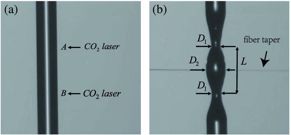
In this work, we will report the experimental observation of the ringing phenomenon in a bottle microresonator. There are several methods that can be used to make bottle microresonators[29,37–39], and an important one is called the heat-and-pull method[38]. Here, a simplified heat-and-pull method was used to fabricate the fiber bottle microresonators. Compared to the method in Ref. [38], gravity instead of a stage was used to pull the fiber. As shown in Fig. 1(a), a single-mode fiber with a diameter of 125 μm was kept vertical by attaching a small weight to its lower end. The fiber was heated by a laser, and the heated point became a microtaper under the pull of the gravity. A manual stage was used to move the fiber up or down so that the position of the heated point could be controlled. A bottle microresonator as shown in Fig. 1(b) was fabricated by making two microtapers on the fiber. If a bottle microresonator with a smaller bottle diameter is needed, we can first heat the fiber by the laser, and at the same time, we can move the fiber up by the manual stage. This process can make a small section of the fiber have a smaller diameter. Then, two microtapers can be made as described above in this section to form a smaller bottle microresonator.
Figure 1.(a) Method to fabricate the fiber bottle microresonator. The fiber is heated by a laser to make two microtapers at positions A and B under the pull of the gravity. Then they will form a bottle microresonator. (b) The bottle resonator studied in the experiment. The long horizontal line is the fiber taper.
The bottle microresonator in Fig. 1(b) was tested in our experiment, where the stem diameter μ, the bottle diameter was μ, and the neck-to-neck distance was μ. A fiber taper with a diameter of about 2 μm was used to couple the laser into and out of the bottle microresonator. These parameters were estimated from a CCD camera attached to a microscope. The fiber taper was placed in the bottle’s center, as shown in Fig. 1(b), and the air gap between them was controlled by a translation stage with a resolution of 20 nm. A tunable continuous-wave laser in the 1550 nm band with a linewidth smaller than 200 kHz was launched into the fiber taper. The output light from the other end of the fiber taper was measured by a 125 MHz low-noise photoreceiver, whose output signal was sent to a digital oscilloscope to obtain the transmission spectrum. A typical transmission spectrum is shown in Fig. 2, where each dip corresponds to a whispering-gallery mode in the bottle microresonator.
Sign up for Chinese Optics Letters TOC. Get the latest issue of Chinese Optics Letters delivered right to you!Sign up now
Figure 2.Transmission spectrum of the bottle resonator.
To investigate a single whispering-gallery mode in detail, a triangle wave signal from a function generator was used to control the fine sweeping of the tunable continuous-wave laser[2]. The wavelength of the laser increased at a constant speed as the voltage of the triangle wave signal increased linearly. The laser power was kept low so that the thermal effect in the bottle microresonator was ignored. A mode with a resonance wavelength of 1536.76 nm was studied, and stable transmission spectra were obtained. A transmission spectrum with a fast laser sweeping speed of 56.81 nm/s is shown in Fig. 3(a), and a transmission spectrum with a slower laser sweeping speed of 2.91 nm/s is shown in Fig. 3(b). It is obvious that the shape of the transmission depends on the laser sweeping speed. The oscillation in the tail of the transmission in Fig. 3(a) shows that a ringing phenomenon in the bottle microresonator is observed. The transmission in Fig. 3(b) is not a symmetrical Lorentz shape because the laser sweeping speed is not slow enough for such a high- mode.
Figure 3.Experimental transmission spectra and theoretical fittings from the dynamic equation. The zero time is set to be the moment that the instantaneous frequency of the laser equals the resonance frequency of the mode. (a) A ringing phenomenon is observed with a fast laser sweeping speed of 56.81 nm/s. (b) Transmission spectrum with a lower laser sweeping speed of 2.91 nm/s.
The ringing phenomenon in Fig. 3(a) can be explained through the dynamic equation governing the field in the resonator. Assume that , , and are used to denote the field in the microresonator, the input field, and the output field, respectively. They are normalized so that represents the energy stored in the microresonator, represents the input power, and represents the output power. The dynamic equation governing the field in the microresonator is where is the resonance angular frequency of the whispering-gallery mode, which is a constant, as the laser power is low and the thermal effect in the bottle microresonator is ignored. The parameter is the intrinsic loss rate, and is the loss rate associated with the fiber taper coupling. Given an expression of the input field , we can find out how changes with time from the dynamic equation, and then find out how the normalized transmission changes with time , where the output field is obtained from the input–output relation For the experiments we have done, the input field can be modeled as[40]where represents the input laser power, and is assumed to be in the following. The instantaneous angular frequency of the laser is , which changes at a constant speed. Assume that when , and the initial laser angular frequency is much larger than the resonance angular frequency of the mode, i.e., . Then, from Eq. (1), there is where . If the values of the related parameters are given, how changes with can be obtained through a numerical integration of the above equation. It is found that when we set , , and the laser frequency’s decreasing speed μ, or 56.81 nm/s, the normalized transmission from the theory will agree very well with the experimental result, as shown in Fig. 3(a). Therefore, the observed ringing phenomenon is explained by the dynamic equation, and from the theoretical fitting parameters, it is found that the mode has an intrinsic quality factor .
The dynamic equation can also be used to explain the observed transmission in Fig. 3(b), where the laser has a lower sweeping speed. To make the normalized transmission from the theory agree well with the experimental result, it is necessary to determine the values of the parameters , , and . We set as before, which is reasonable since what we are testing is the same mode, and is the intrinsic loss rate. It was mentioned that the laser sweeping is controlled by a triangle wave signal. The experimental data shown in Fig. 3(a) is obtained when the frequency of the triangle wave is 195 Hz, and the experimental data shown in Fig. 3(b) is obtained when the frequency of the triangle wave is 10 Hz. Since the laser sweeping speed is proportional to the frequency of the triangle wave, we can set the laser frequency decreasing speed to be or 2.91 nm/s, where μ is the value of that is used to explain the experimental result in Fig. 3(a). It is found that when we set , the normalized transmission from the theory will agree well with the experimental result, as shown in Fig. 3(b). Here, a different value of is used because the air gap between the fiber taper and the bottle resonator is different in the two experiments.
The observed ringing phenomenon shown in Fig. 3(a) can be qualitatively understood as follows. When the laser sweeps across the mode, some light has been coupled into the resonator. As the quality factor of the mode is high and the laser sweeping speed is fast, the time needed to sweep across the mode linewidth will be comparable to or even smaller than the lifetime of the light stored in the bottle resonator. Therefore, some light will continue to leak out from the resonator even after the laser has swept over the mode, which will interfere with the directly transmitted light and lead to the ringing phenomenon. Based on this understanding of the ringing phenomenon, we can assume that after the laser sweeps over the mode, the light stored in the resonator will oscillate with the mode resonant angular frequency and decay with at a rate of . So we propose the following function to describe the light field in the bottle microresonator after the laser has swept over the mode: where is a constant and is the moment that the instantaneous frequency of the laser equals the resonant frequency of the mode, i.e., when . The constant represents the amplitude of the light stored in the resonator, which is usually a complex number, since it contains the phase information of at . For the experimental ringing data shown in Fig. 3(a), we set the constant , and plot the new theoretic normalized transmission in Fig. 4(a). It can be seen that also agrees well with the observed ringing spectrum. Therefore, it is good to use the decaying function in Eq. (5) to describe the light field in the resonator to explain the observed ringing phenomenon. Physically, this result confirms the understanding that the ringing phenomenon is the interference between the transmitted laser light and decaying light from the resonator.
Figure 4.(a) The observed ringing spectrum and the new theoretical fitting with the function in Eq. (5) describing the light in the resonator. The zero time is set to be the moment that the instantaneous frequency of the laser equals the resonance frequency of the mode. (b) Comparison of the light field intensity in the resonator predicted by the two theories. The result from the dynamic equation (blue line) shows that there will be an oscillation.
However, it should be recalled that there is still some difference between the decaying function in Eq. (5) and in Eq. (4). In Fig. 4(b), we compare and and find that there is an oscillation in , which means that if we measure the light field intensity in the resonator, the result from the dynamic equation predicts that an oscillation can be observed, while the result based on the decaying function predicts no oscillation. We can compare both the real and the imaginary parts of and to see the difference between and , and the result is shown in Fig. 5. It can be seen that the real parts agree quite well, but the imaginary parts have some difference. Note and have some difference, why do they lead to theoretical transmissions that both agree well with the experimental results in Figs. 3(a) and 4(a)? This is because the magnitudea of and are both small [see Fig. 4(b)], so their imaginary parts only have a very small effect on the normalized transmission, which can be seen from the expressions and .
Figure 5.Comparison of the real and the imaginary parts of and in (a) and (b), respectively. It can be seen that the real parts agree very well. The zero time is set to be the moment that the instantaneous frequency of the laser equals the resonance frequency of the mode.
In conclusion, a method using gravity instead of a stage to fabricate fiber bottle microresonators is demonstrated. The quality factor value of the fabricated bottle microresonator can reach a magnitude of , and a ringing phenomenon in the transmission spectrum is observed. The observed transmission spectra of the bottle resonator are well explained by the dynamic equation governing the light field in the resonator. In addition, it is shown that a decaying function can also be used to describe the light field in the resonator to explain the observed ringing phenomenon.