
Jia Xu, Zhenglin Liu, Keming Pan, Daomu Zhao. Asymmetric rotating array beams with free movement and revolution[J]. Chinese Optics Letters, 2022, 20(2): 022602
- Chinese Optics Letters
- Vol. 20, Issue 2, 022602 (2022)
Abstract
Keywords
1. Introduction
In the space-frequency formulation of the coherence theory of stationary optical fields, the cross-spectral density (CSD) function superimposed by the coherent propagation mode has attracted wide attention. To gain some insight about properties of fields radiated by sources of different states of coherence, the Gaussian Schell model (GSM) source is widely used, which can bring simpler analysis results for the non-trivial incident field and media of the beam interaction[
In order to design a novel beam field, the conditions of the amplitude and phase of the complex coherence in one and two dimensions are derived theoretically[
Here, we show a type of random source whose CSD combines the lobe rotation, the beam revolution, and linear shifts of the array. We establish such a beam and then explore its process of propagation as a controllable two-dimensional optical array that carries rotating and revolving structures. It is noteworthy that, while the rotating phase is capable of producing rotating beams upon propagation, the linear Cartesian phase is responsible for splitting beams, obtaining a series of replicas and then forming the asymmetric array according to the shifting of different weights.
Sign up for Chinese Optics Letters TOC. Get the latest issue of Chinese Optics Letters delivered right to you!Sign up now
2. Theory
Let us first review the main theoretical descriptions related to stationary beams. Suppose that a scalar random beam-like field is generated from a planar source located in the plane of and then propagated in the direction of positive . In optical coherence theory[
We will first illustrate how the rotating array spectral density can be obtained directly. An anisotropic Gaussian correlated field with linear shifting parameters is required[
uses the following form to generate a light source with a partially coherent beam with the characteristics of revolution and rotation:
According to the generalized Huygens–Fresnel principle, the CSD that is propagated by the optical ABCD system in the transverse plane is characterized by[
Here, denotes the wavenumber, and is the optical wavelength in free space. is the position vector in the output plane. Now, set the same position coordinate in the CSD formula to obtain the spectral density during propagation, , and the DOC of two symmetric points with respect to the optical axis, .
Next, in order to better study the morphological characteristics of the beam in the propagation process, we consider adding a lens system, whose transfer matrix can be given by the following formula:
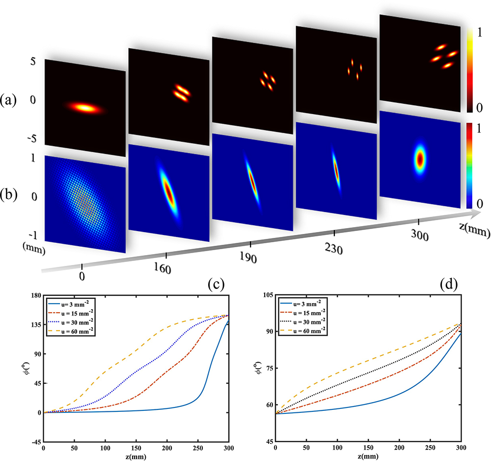
The propagation characteristics of an ARGSMA beam are depicted in Figs. 1(a)–1(d). Figure 1(a) represents the spectral density of a row of light beams along the propagation direction. Figure 1(b) is the DOC corresponding to Fig. 1(a). The rotation of spectral density is slow first, then fast, and then slow, as seen in Fig. 1(c). In order to perfectly represent the shape of each stage of rotation, non-equal spacing is used here to select iconic diagrams. Specifically, five specific positions are given in Figs. 1(a) and 1(b), which are , 160, 190, 230, and 300 mm. The initial Gaussian ellipse progressively splits into a rotating Gaussian array upon propagation, which moves along the line at an angle to the diagonal shown, as in Fig. 1(a). Each individual lobe of spectral density rotates clockwise all the way around its own central axis in a synchronous motion. The line in Fig. 1(c) also explains the corresponding entire rotation process of spectral density from to 300 mm. In the beginning, although the beam can undergo lower speed of a smaller twist, it can speed up and complete a larger and even a twist of 150 deg. The larger the is, the earlier the acceleration starts in Figs. 1(c). Furthermore, Fig. 1(b) presents DOC of the field. It is demonstrated that when the beam propagates, the DOC rotates clockwise around the beam axis and then degenerates into a Gaussian profile. The of different values corresponds to DOC, as shown in Fig. 1(d). In this respect, the rotating array beam can be a potential tool for dynamic control of multiple particles.
![]()
Figure 1.Propagation dynamics of the beams with (a) spectral density and (b) DOC. Calculated parameters are set as follows: µ = 15 mm−2; ηx = ηy = 60; Nx = Ny = 2; σx = δx = 1 mm; σy = δy = 0.3 mm; α = π/8; θ = 2π/3. Rotation angles versus propagation distance z with u = 3, 15, 30, and 60 mm−2 for (c) spectral density and (d) DOC.
Having shown the intriguing property of beams, it is instructive to study the dependency of the light intensity distributions. As clearly seen from Fig. 1(a), the central axis of this beam is not simply along the axis during propagation, but with the lateral shift. The parameter determines the amount and direction of the lateral shift, as shown in Fig. 2. Particularly, asymmetric characteristics about the axis and the axis depend on negative and positive numbers. It means that when , the array beam will be moved to the upper right direction. On the contrary, when , the array beam will be moved to the bottom left direction. In the same way, when and , the array beam will be moved to the upper left direction. On the contrary, when and , the array beam will be moved to the bottom left direction. The intensity remains symmetric about both axes when . Meanwhile, it is also possible to achieve only one axial symmetry by changing its number. To develop an understanding of the transverse plane shifts, the specific splitting process of Figs. 2(e) to 2(i) is given above. As the value of gradually increases, the beam gradually splits and spreads in a certain direction. What is more, it is also noticeable that the value of the parameter determines the dimension of the array.
![]()
Figure 2.Free movement of spectral densities with different values of ηs. Calculated parameters are set as follows: µ = 15 mm−2; z = 190 mm; Nx = 4; Ny = 3; σx = δx = 1 mm; σy = δy = 0.3 mm; α = 0; θ = 2π/3.
As shown in Fig. 3, it is worth mentioning that the revolution of the array beam and rotation of each lobe is controlled by and , respectively. To be specific, Fig. 3(a) shows that the array beam revolves around the fixed center of the figure and completes a circle, as increases from 0 to . Figure 3(b) shows the size of will affect the rotation direction of each lobe. and are the special points. At these two points, the lobe does not rotate. From to , it rotates clockwise. During 0 to and to , the rotation is counterclockwise. Then, it takes as the cycle to repeat itself ad infinitum. There are five special values given in Fig. 3(b), in which is in perfect agreement with the transmission process in Fig. 1. Also, the corresponding points of the special values in Fig. 3(b) have been clearly marked in the periodic graph in Fig. 3(c) in order to illustrate the generality of the conclusion.
![]()
Figure 3.(a) Revolution angles of the array beam with different values of α. Calculated parameters are set as follows: µ = 15 mm−2; z = 190 mm; ηx = ηy = 60; Nx = Ny = 3; σx = δx = 1 mm; σy = δy = 0.3 mm; θ = 2π/3. (b) Rotation angles of the lobes during transmission with θ = 0, π/8, π/4, π/3, and 2π/3. (c) The relationship between the rotation angles of the lobes and θ at z = f.
3. Experiment
The sketch of the experimental setup is shown in Fig. 4. The Gaussian beam is emitted by a 532 nm linearly polarized semiconductor laser, and it then passes through a polarizing beam splitter (PBS) to control the power of the beam. In order to achieve the amplitude of the modulated beam, SLM1 must be distributed with a prescribed intensity. So by combining two linear polarizers (LP1 and LP2), the polarization direction of the beam after passing through the beam expander and facing SLM1 (LC2012) is easily controlled. For the purpose of filtering out stray lights, a system (L1 and L2) with an iris is established. After the laser beam passes through the rotating ground-glass disk (RGGD), the GSM correlation is generated[
![]()
Figure 4.Experimental setup for generating an ARGSMA beam. LP, linear polarizer; PBS, polarizing beam splitter; BE, beam expander; SLM, spatial light modulator; L, lens; RGGD, rotating ground-glass disk; GAF, Gaussian amplitude filter; CCD, charge-coupled device; PC, personal computer.
The experimental parameters are consistent with the simulation values, which is easy to facilitate research, comparison, and verification. It can be seen that the results of the experiment shown in Fig. 5 are in good agreement with the numerical simulations shown earlier. First of all, it can be seen from the first set of experimental graphs that the transmission behavior of the spectral density of ARGSMA and DOC is in perfect agreement with Fig. 1. Specifically, the process of lobes splitting, the revolution direction of the array controlled by , the rotation behavior of the lobe controlled by , and the final rotation angle reached are in good agreement with Fig. 1(a). Similarly, the deflection direction and angle of the DOC correspond well to Fig. 1(b). Subsequently, in order to give a better understanding of the dispersion mechanism of the array, the experimental diagram in Figs. 5(b1)–5(b4) verifies the process of the theoretical simulation of Figs. 2(e) to 2(i) changing with increasing and clearly verifies the relationship of the linear shift parameter with different values, which are positive or negative, and the lobes, which change in position and distance.
![]()
Figure 5.(a1) Spectral density and (a2) DOC of the ARGSMA beam during transmission from the experiment and the parameters as in Fig.
4. Conclusions
In summary, we have modeled a new family of random sources described by a revolving CSD being a linear combination of the CSDs with rotation that radiates far fields with array-like spectral densities and non-trivial distributions. Analysis shows that this type of beam can control source parameters to arbitrarily tailor revolution of the array beam and rotation of each lobe, gaining larger freedom in the field of rotary engineering. Furthermore, we demonstrated how the far-field spectra, and also found that the dimensions of the arrays, can be easily adjusted by changing the summing index in the function. By combining the construction of a partially coherent beam and the SLM loading phase, this type of ARGSMA beam is produced experimentally. Consistent with expectations, the experimental phenomena and numerical simulations basically fit. We foresee a broad range of applications for this new class of rotating beams from optical trapping and conveying, where the beam rotates and plays significant roles. More importantly, we hope that the results obtained here can realize the broadening of the field of asymmetric coherent gratings and lattices and have further enlightening research.
References
[1] F. Gori, M. Santarsiero. Devising genuine spatial correlation functions. Opt. Lett., 32, 3531(2007).
[2] S. Sahin, O. Korotkova. Light sources generating far fields with tunable flat profiles. Opt. Lett., 37, 2970(2012).
[3] L. Wan, D. Zhao. Twisted Gaussian Schell-model array beams. Opt. Lett., 43, 3554(2018).
[4] J. Xu, K. Pan, D. Zhao. Random sources generating hollow array beams. Opt. Express, 28, 16772(2020).
[5] C. Liang, F. Wang, X. Liu, Y. Cai, O. Korotkova. Experimental generation of cosine-Gaussian-correlated Schell-model beams with rectangular symmetry. Opt. Lett., 39, 769(2014).
[6] Z. Liu, D. Zhao. Experimental generation of a kind of reversal rotating beams. Opt. Express, 28, 2884(2020).
[7] O. Korotkova, X. Chen. Phase structuring of the complex degree of coherence. Opt. Lett., 43, 4727(2018).
[8] X. Chen, O. Korotkova. Complex degree of coherence modeling with famous planar curves. Opt. Lett., 43, 6049(2018).
[9] X. Chen, O. Korotkova. Phase structuring of 2D complex coherence states. Opt. Lett., 44, 2470(2019).
[10] B. Sun, Z. Huang, X. Zhu, D. Wu, Y. Chen, F. Wang, Y. Cai, O. Korotkova. Random source for generating Airy-like spectral density in the far field. Opt. Express, 28, 7128(2020).
[11] Z. Mei, O. Korotkova. Asymmetric coherence gratings. Opt. Lett., 45, 1366(2020).
[12] Z. Mei, O. Korotkova. Cross-spectral densities with helical-Cartesian phases. Opt. Express, 28, 20438(2020).
[13] K. Sundar, R. Simon, N. Mukunda. Twisted Gaussian Schell-model beams. J. Opt. Soc. Am. A, 10, 2017(1993).
[14] R. Borghi, F. Gori, G. Guattari, M. Santarsiero. Twisted Schell-model beams with axial symmetry. Opt. Lett., 40, 4504(2015).
[15] Z. Mei, O. Korotkova. Random sources for rotating spectral densities. Opt. Lett., 42, 255(2017).
[16] F. Gori, M. Santarsiero. Devising genuine twisted cross-spectral densities. Opt. Lett., 43, 595(2018).
[17] R. Borghi. Twisting partially coherent light. Opt. Lett., 43, 1627(2018).
[18] L. Wan, D. Zhao. Controllable rotating Gaussian Schell-model beams. Opt. Lett., 44, 735(2019).
[19] K. Pan, J. Xu, D. Zhao. Partially coherent sources with the combined quadratic phase. Opt. Commun., 478, 126392(2021).
[20] E. Wolf. Introduction to the Theory of Coherence and Polarization of Light(2007).
[21] S. A. Collins. Lens-system diffraction integral written in terms of matrix optics. J. Opt. Soc. Am., 60, 1168(1970).
[22] Q. Lin, Y. Cai. Tensor ABCD law for partially coherent twisted anisotropic Gaussian-Schell model beams. Opt. Lett., 27, 216(2002).
[23] M. Rousseau. Statistical properties of optical fields scattered by random media. Application to rotating ground glass. J. Opt. Soc. Am., 61, 1307(1971).
[24] M. Mitchell, Z. Chen, M. Shih, M. Segev. Self-trapping of partially spatially incoherent light. J. Apl. Phys., 77, 490(1996).
[25] Y. Cai, Y. Chen, F. Wang. Generation and propagation of partially coherent beams with nonconventional correlation functions: a review. J. Opt. Soc. Am. A, 31, 2083(2014).

Set citation alerts for the article
Please enter your email address
© Copyright 2018-2021 | Chinese Laser Press. All Rights Reserved 沪ICP备15018463号-20