Huaping Zang, Chenglong Zheng, Quanping Fan, Chuanke Wang, Lai Wei, Leifeng Cao, Xiangru Wang, Erjun Liang, "Generation of X-ray vortex with ultra-long depth of focus using axial line-focused spiral zone plates," Chin. Opt. Lett. 16, 080501 (2018)
Copy Citation Text
We propose axial line-focused spiral zone plates (ALFSZPs) for generating tightly focused X-ray vortex beams with ultra-long depth of focus (DOF) along the propagation direction. In this typical design, compared with the conventional spiral zone plates (SZPs) under the same numerical aperture (NA), the DOF of ALFSZPs has been extended to an ultra-length by optimizing the corresponding parameters. Besides, it also exhibits lower side lobes and smaller dark cores in the whole focus volume. The diameters of dark cores increase as the topological charge value increases.
The ubiquity of wavefront dislocations, including singularities in the phase ordinarily referred to as screw-type dislocations or optical vortices, has been commonly recognized[1–3]. Profiting from the unique physical properties as non-diffraction, carrying orbital angular momentum (OAM), and self-reconstruction, optical vortices have exercised the imagination of the optics community to a great degree over the past decades[4,5]. Potential applications, including optical communication[6–8], micro-manipulation[9–12], high-resolution imaging[13], and lithography[14], have been investigated and demonstrated. Recently, a desired confirmation of X-ray vortices at 9 keV has been reported, offering whole new possible fields of investigation[15]. For instance, in X-ray astronomy, it may be a feasible method to examine a weak background signal very close to a bright coherent source[16]. For micro-machines, we can take advantage of elemental characteristic absorption energies to realize the selective transfer of OAM[17].
Diffractive optical elements (DOEs), such as spiral phase plates (SPPs)[18], spiral zone plates (SZPs)[19,20], and spiral photon sieves (SPSs)[21], have been discussed for producing X-ray vortices. For SPPs, which contain a helical phase profile ( is a signed nonzero integer termed as the topological charge, and is the azimuth angle), however, the imperfect fabrication of an approximate spiral ramp will inevitably introduce extra errors. Furthermore, considering the rapid divergence of the focused vortex beam after passing through the focal volume, elements with a relatively long depth of focus (DOF) are claimed in the process of producing X-ray vortices. Consequently, the physical feature of X-ray vortices in terms of long focal fields unavoidably plays an important role in the applications of micro-manipulation, imaging edge-enhanced techniques, X-ray astronomy, as well as lithography, etc.
We note that, in particular, for the most straightforward application of X-ray vortices in micro-manipulation, obviously only a long focal volume guarantees it to be a powerful implement for trapping and rotating the particles in the space and time domain simultaneously. As a consequence of the stability of vortices, the wave fields made from photons that carry OAM have encouraged the application to lithography[4]. Moreover, considering the accuracy in collimation, non-diffraction structures are also needed. Besides, DOEs with long DOF and high-resolution are also playing an important role in the procedure of three-dimensional images of objects for eliminating distortion and aberration[13]. Hence, further improvements of long DOF still have been required for the binary structures, such as SZPs and SPSs. It is known to us that there is a trade-off relationship between the DOF and the lateral resolution for DOEs. High lateral resolution requires a high numerical aperture (NA), whereas long DOF requires low NA instead[22]. Obviously, these two goals cannot be achieved simultaneously.
Sign up for Chinese Optics Letters TOC. Get the latest issue of Chinese Optics Letters delivered right to you!Sign up now
To overcome these drawbacks, we propose a novel DOE that is called axial line-focused spiral zone plates (ALFSZPs) for generating an X-ray vortex with long DOF along the propagation direction. Meanwhile, the diameters of the hollow beams and side lobes remain small and low in the whole focal volume compared with SZPs under the same NA. The principle is realized by implementing a phase stagger between two adjacent zones of conventional SZPs. This DOE is compatible with the multi-wavelength from optical wavebands to X-rays. Besides, the influence of the parameters on the focusing properties has also been discussed in detail. For the purpose of investigation, we will summarize and address these points in the following.
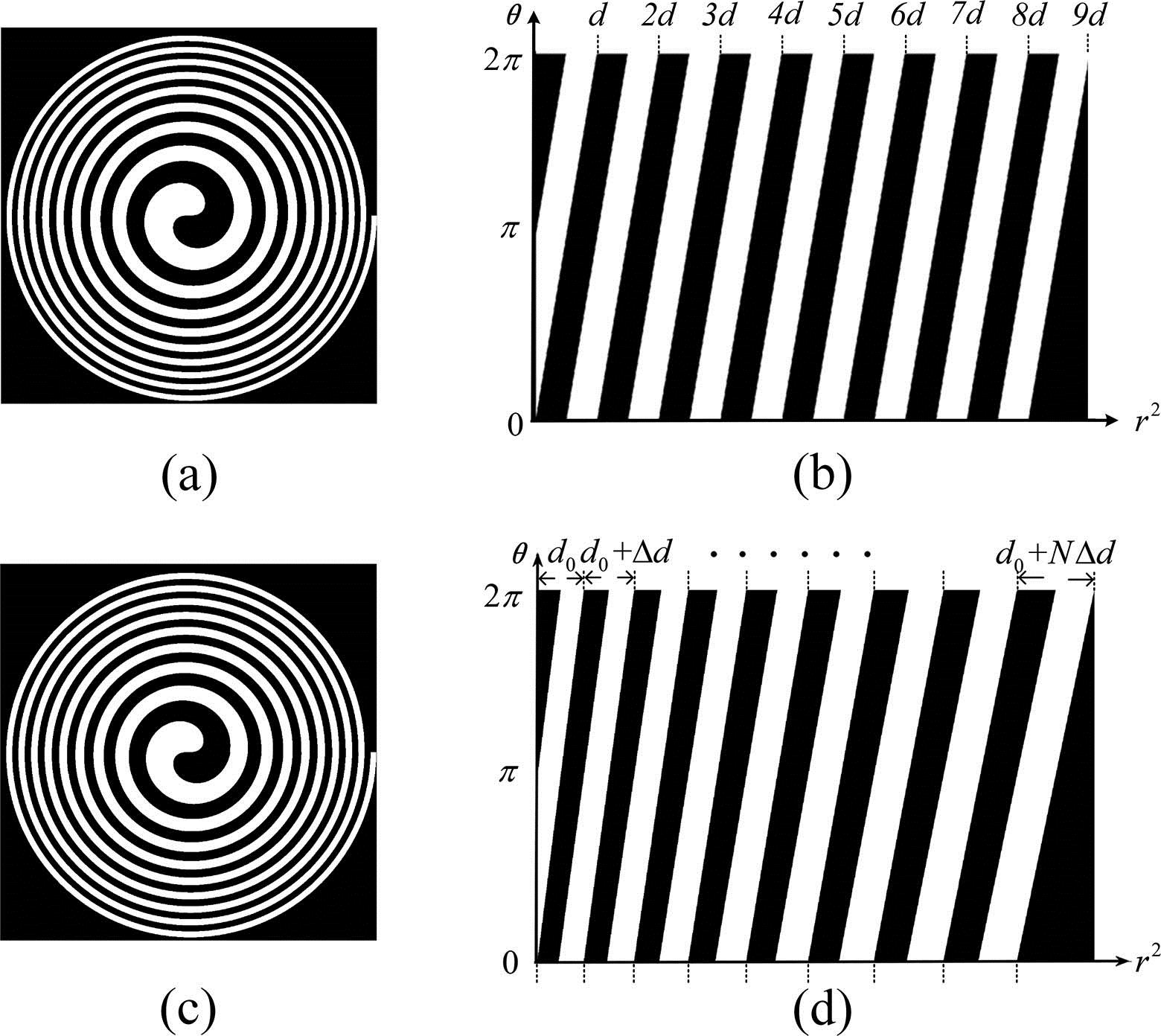
We start the design based on conventional SZPs, as presented in Fig. 1(a). As shown in Fig. 1(b), the corresponding pattern in the polar coordinate (, ) has also been provided. Commonly, using SZPs as a single element objective is equivalent to optically implementing the radial Hilbert filtering operation and the Fresnel zone plate (FZP) focusing operation in a single step. Consequently, we can obtain SZPs by multiplying the radial Hilbert phase function with the ZP phase function, which can be expressed as where represents the topological charge, and are the polar coordinates, is the incident wavelength, and is the focal length. For penetration in the X-ray regime, diffraction optics is generally constrained due to fabrication errors. Then, the SZPs phase in Eq. (1) can be binarized as the transmittance function in Eq. (2), where is a constant angle denoting the starting orientation of the azimuth :
Figure 1.Transmittance for SZPs with the topological charge in (a) the (, ) coordinate system and (b) the (, ) coordinate system. Transmittance for ALFSZPs with the topological charge in (c) the (, ) coordinate system and (d) the (, ) coordinate system.
In principle, such SZPs would produce optical vortex at the focal plane, which depends on the focal length. Based on this, we propose a technique for generating an X-ray vortex with long DOF, which is called ALFSZPs, as illustrated in Fig. 1(c). As mentioned, instead of a series of concentric rings, like FZPs, the ALFSZPs consist of a series of alternative transparent and opaque screw ramps similar to the SZPs. However, differing from the transmittance, as in Eq. (2), for the SZPs, there is a phase stagger between two adjacent wave zones, which is introduced by a varied area for ALFSZPs. We will address this point in the following.
As presented in Figs. 1(c) and 1(d), the transmittance function of ALFSZPs is illustrated in the (, ) coordinate system and (, ) polar coordinate, respectively. It can be seen in Fig. 1(d) that one groove equals one pair of wave zones, which include a transparent zone and an opaque zone. For explicitness, we discuss the design process in the polar coordinate at the position of for each period, as the widths of the wave zones are varied with the azimuthal coordinate . We assume the width of the initiative groove is , and, then, we endow the sequence adjacent grooves with a successive variation , which abides by the arithmetic progression. Following this principle, an area-varying feature will appear between two adjacent screw ramps. Typically, it is clear that as the parameter , then ALFSZPs will reduce to SZPs. Additionally, here, we only perform the case that the widths of the grooves increase with the square of the radius . Similarly, based on our previous work[22], the internal and external boundaries of the transparent bars of the th groove can be written as
Accordingly, it will obviously introduce a phase correction for the transmittance in Eq. (2). Then, the transmittance for the ALFSZPs can be written as where represents the th wave zone, and represents the corresponding focal length. Using the relationship between the radius and azimuth , the phase correction can be expressed as . It is clear that each annulus contributes to one focal vortex at the corresponding focal plane and, then, a series of successive vortices can be effectively produced in the designed focal volume. In other words, a focused vortex beam with an ultra-long DOF can be realized by optimizing the parameters of the ALFSZPs, saying the variation of the adjacent grooves and the total number of the grooves . Similar with the calculation methodology for the linear varied-area zone plates (LVAZPs), here, the total DOF for ALFSZPs can be calculated with [22]. Meanwhile, the focal volume can be modulated within , and focal length can also be represented as . We will discuss how it can be unambiguously created and verified. The design will be confirmed with simulation in the following sections. Based on this, we anticipate that the desirable physical properties of ALFSZPs encourage the extensive applications in fields of non-diffraction X-ray vortex beams, such as micro-manipulation, lithography, and astronomy, with quality accuracy.
In particular, since the structure of ALFSZPs has no periodic feature, the corresponding intensity distribution cannot be expressed by an analytical method. Next, we will present the simulation results based on the transmittance to validate the physical design. Consider a plane wave of unit amplitude and wavelength normally incident on ALFSZPs, according to Fresnel diffraction theory, the far-field complex amplitude can be written as where is the axial distance away from the ALFSZPs, and represents the transmittance of the ALFSZPs. As illustrated in Fig. 2, differing from the SZPs, after modulation by ALFSZPs, the plane wave incident on different transparent wave zones will be focused at different positions because of the phase stagger between the adjacent wave zones. Finally, a hollow columnar profiled focus with a longitudinally quasi-homogenous intensity distribution can be produced. Furthermore, we assume that the parameters have been appropriately adjusted, and then a vortex laser beam with long DOF will be successfully realized.
Figure 2.Schematic diagram of diffraction by the ALFSZPs.
Nevertheless, in the X-ray regimes, the opaque zone of zone plates (ZPs), as illustrated in Fig. 1, is partially transparent due to the strong penetration. In practice, the absorption material is generally high- foil, such as gold. Hence, the binary transmittance described in Eq. (3) should be corrected as a particularly simple mathematical description:
The parameter is the thickness of the gold foil with the value of 500 nm in the attached calculation. Besides, the parameters and are corresponding optical constants, which vary with different incident wavelengths. Here, these parameters are chosen as , , , and . For the analysis of the focusing behavior of ALFSZPs, we assume the validity of the paraxial approximation. Based on this, we will focus on the focusing properties of the elements and analyze the influence of parameters by substituting Eq. (3) into Eq. (4).
In our investigation, to evaluate the advantages of ALFSZPs by simulation, a direct comparison for the focusing properties of SZPs and ALFSZPs is necessary. In the simulation, the central focal length is assumed as 500 mm, and the topological charge is . As illustrated, Figs. 3(a) and 3(b) display the axial irradiances of conventional SZPs and ALFSZPs along the propagation direction with the same parameters, respectively. Moreover, according to our physical design, the parameters as the total zone number and the phase stagger introduced by the varied area between two adjacent wave zones will definitely influence the axial irradiance of ALFSZPs. Therefore, as shown in Figs. 3(c) and 3(d), we also discuss the consequent influence on the focusing properties of ALFSZPs with different parameters.
Figure 3.(a) The calculated axial irradiance of conventional SZPs; (b) the calculated axial irradiance of ALFSZPs with focal depths from 450 to 550 mm, , , and μ; (c) the calculated axial irradiance of ALFSZPs with focal depths from 475 to 525 mm, , , and μ; (d) the calculated axial irradiance of ALFSZPs with focal depths from 475 to 525 mm, , , and μ.
As expected, we can see from Fig. 3(a) that a symmetrical X-ray vortex with homogenous intensity distribution has been generated at the first order focal plane of 500 mm. As mentioned, SZPs have been extensively applied in fields of X-ray astronomy and the imaging edge-enhanced technique with good focusing performances, such as smaller focal spot, peak intensity, as well as a planar fabricated process, compared with SPPs. However, considering the quick divergence of the vortex beyond the focal volume, the existing imperfection in terms of the only several micrometers DOF restrains further application. In contrast, for ALFSZPs, the DOFs for ALFSZPs are designed as 100 and 50 mm in Figs. 3(b)–3(d), respectively. As expected, we can obtain from Figs. 3(b)–3(d) that ALFSZPs produce a uniform X-ray vortex beam in the corresponding focal region. The DOF has been enhanced almost hundreds of times compared with SZPs, although the diameters and the intensity distribution of the hollow beams preserve a small oscillation. Additionally, we can obtain that the cross section peak intensity distribution of the vortex beams decreases with the same factor as the DOF increases, keeping the total intensity of the foci nearly the same. Arbitrary orders of magnitude enlargement of the DOF will be further verified by optimizing the corresponding parameters, and the oscillation for the diameters and intensity of the vortex beam will be also minimized. The good performance and stabilization for long distance propagation of the X-ray vortex beams generated by ALFSZPs make it a vital and irreplaceable element in the unprecedented applications involving ultra-long DOF, such as optical trapping and manipulation of nanostructures. In general, the simulations accord with our physical design.
Apart from the good performance on enlarging the DOF, another vital advantage of ALFSZPs is the simultaneous preservation of small dark cores and low side lobes in the whole focal volume. As we mentioned above, the simultaneous enlargement of the DOF and reduction of the diameters of the dark cores are two contradictory features to explore. As shown in Fig. 4, we calculate the diffraction patterns at different distances away from the ZP samples with the same parameters as in Figs. 3(a) and 3(b). As we list in the first line, Figs. 4(a)–4(c) represent the diffraction patterns of ALFSZPs at the distance of 450, 500, and 550 mm, respectively. Meanwhile, the figures in the second line represent the diffraction patterns of SZPs at the corresponding distance. Obviously, although an X-ray vortex has indeed been generated at the focal plane of 500 mm for SZPs, the vortex beam quickly diverges at 450 and 550 mm with a strong side lobes background. In contrast, within the defocus distance of , the ALFSZPs preserve smaller lateral spot sizes and lower side lobes. We can see that the lateral spatial resolution is even better as the distances increase for the ALFSZPs. Consequently, apart from the ultra-long DOF, the focusing properties of the ALFSZPs imply better spatial resolution and higher precision during application.
Figure 4.(a), (b), and (c) Calculated diffraction patterns of ALFSZPs at the positions of 450, 500, and 550 mm. (d), (e), and (f) Calculated diffraction patters of conventional SZPs with the same parameters at the positions of 450, 500, and 550 mm.
Furthermore, the focusing properties of the ALFSZPs with different topological charges have been also investigated with the parameters, as in Fig. 3(b). As presented in Fig. 5, the transmittance and axial irradiance from 450 to 550 mm have been discussed, respectively. As shown in Fig. 5(a), in the case of topological charge , ALFSZPs reduce to LVAZPs. As presented in Figs. 5(d) and 5(f) with and , it indicates that the doughnut patterns and the sizes of dark cores will expand as the topological charges increase, which is similar to the focusing properties of SZPs. In all, we summarize that the vortex beams generated by ALFSZPs can be controlled by the parameters, such as topological charges, total wave zones, and the phase staggers between two adjacent wave zones in terms of DOF, radius, and profiles, which may be useful for manipulating nanostructures and particles. Apart from the outstanding feature on adjustable DOFs, the ALFSZPs also offer notable physical characteristics, like good symmetry, lower side lobes, non-diffraction, as well as better lateral resolution and quality accuracy in the whole focal volume.
Figure 5.ALFSZPs with different integer topological charges and axial irradiances from 450 to 550 mm. (a), (b) The topological charge . (c), (d) The topological charge . (e), (f) The topological charge .
We have proposed a new technique for generating an X-ray vortex with ultra-long DOF, which is called ALFSZPs. It can be realized by alternately arranging a series of spiral annulus with transparent and opaque transmittance as the conventional SZPs. However, differing from SZPs, it preserves a flexible phase stagger between two adjacent wave zones. According to our calculation, compared with SZPs under the same circumstance, the DOF of the vortex generated by ALFSZPs can be significantly enhanced, while the diameters of the hollow beams and the side lobes retain the same in the whole focus volume, implying better spatial resolution and higher precision during application. Moreover, ultra-long DOF can be realized by appropriately adjusting the corresponding parameters. The diameters of the hollow beams increase as the topological charge increases. The focusing performance of ALFSZPs provides possible alternatives in manipulation, X-ray astronomy, lithography, etc.