1State Key Laboratory of Electronic Thin Films and Integrated Devices, University of Electronic Science and Technology of China, Chengdu 610054, China
2Information Materials and Device Applications Key Laboratory of Sichuan Provincial Universities, Chengdu University of Information Technology, Chengdu 610225, China
Compared to pure vortex waves, the superposition state of spherical waves and vortex waves has enough degrees of freedom to upgrade applications in particle manipulation, information encryption, and large-capacity communications. Here, we propose a new scheme to achieve superposition states and multichannel transmission of vortex and spherical waves. Two transmissive all-silicon metasurfaces that enable mutual interference between linearly polarized (LP) waves in the terahertz region are demonstrated. Type A can achieve interference between and polarized waves, while type B can achieve interference between (or ) and (or ) polarized waves. The multichannel transmission and superposition states of topological charges of , , and are designed and demonstrated from theoretical, simulative, and experimental perspectives at 1.1 THz. In addition, the objective fact that the focused superposition state must be observed close to the focal plane is also revealed. The measured results are in good agreement with the theoretical and simulative results. This work provides an idea for the design of ultrathin terahertz devices and could be applied in the fields of information encryption and high-frequency communications.
1. INTRODUCTION
A vortex beam, as one of the optical vortices, has continuous spiral wavefronts and annular light intensity distributions (with a phase singularity in the center) due to the existence of orbital angular momentum (OAM) [1]. Specifically, a vortex beam has a helical phase described by , where and are the angular coordinate and topological charge, respectively. The OAM value carried by the photon is ; that is, the OAM value is controlled by the eigenvalue parameter , which links classical and quantum optics [2]. The OAM is usually used as a carrier for the interaction and information transmission between photons and particles or matter; thus, many interesting works have been born, including particle manipulation [2,3], “optical wrenches” [4], interference detection [5,6], optical communications [7,8], microscopy imaging [9], and quantum information encoding [10]. Notably, the interference between vortex waves with a certain topological charge and other waves can produce many unexpected phase distributions; that is, superposition states between different waves. The superposition state of different waves could upgrade the applications mentioned above, by, for example, improving the accuracy of particle manipulation, broadening the channel of optical communications, and integrating more functions.
The methods to acquire superposition states between different waves include interferometry [11–13], Doppler analysis [14], diffraction grating [15,16], and metasurface [17–19]. Among them, the metasurface method is outstanding in considering the complexity and stability of the system, diffraction efficiency, spatial resolution, and flexible control of electromagnetic waves. It has enough degrees of freedom to design structures composed of metallic or dielectric resonators for efficient phase-controlled light [20–23]. At present, the related applications of metasurfaces are mainly localized in chiral lenses [24–27], the optical spin Hall effect [28,29], beam splitting [25,30], focusing [31–33], holographic projection [34,35], communications coding [36–38], sensing [39], and vortex beam generator [40,41]. It should be noted that the superposition state between the vortex and vortex waves based on the metasurface has been successfully realized, including the superposition state generators of spin-dependent and spin-independent OAM [2,42]. However, there are still few works that address the multifunctional integration and the superposition state between planar (or spherical) and vortex waves, especially terahertz devices that consider size, stability, resolution, and processing difficulty.
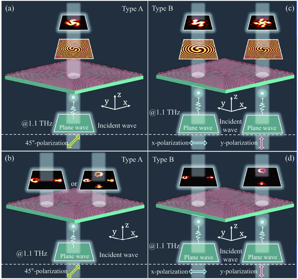
In this paper, we propose all-silicon terahertz metasurfaces that can be used to generate superposition states and multichannel transmission of linearly polarized (LP) spherical and vortex waves. Based on the anisotropic units of a cross-ellipse structure, two kinds of transmissive metasurfaces that interfere with each other between LP waves are demonstrated. Type A can achieve interference between and polarized waves, while type B can achieve interference between (or ) and (or ) polarized waves. As a demonstration of the concept, we design the superposition states and multichannel transmission of the spherical and vortex waves (, and ) from both theoretical and simulation perspectives, as shown in Figs. 1(a)–1(d). Superposition states of spherical and vortex waves are generated in the incident , , and 45° polarized waves. Two and four channels are also generated in the incident (or ) and 45° polarization waves, respectively, to carry multiple spherical and vortex waves. Furthermore, to measure the physical phenomenon of this superposition state, the introduction of a focusing function is necessary. We experimentally observe superposition states with topological charges of and close to the focal point. We believe that the designed metasurfaces provide ideas for the design of ultrathin photonic devices and facilitate the development of terahertz information encryption and high-frequency communications.
Sign up for Photonics Research TOC. Get the latest issue of Photonics Research delivered right to you!Sign up now
Figure 1.Functional illustrations of LP multichannel transmission and superposition states of spherical and vortex waves. (a) Superposition state of spherical wave and vortex wave () under 45° polarized wave incidence. (b) Four-channel transmission of two spherical waves and two vortex waves ( and ) can be carried under 45° polarized wave incidence. (c) Superposition states of spherical wave and vortex wave ( and ) under and polarized wave incidence, respectively. (d) Two-channel transmission of a spherical wave and a vortex wave ( or ) can be carried under (or ) polarized wave incidence.
To realize multichannel transmission and superposition states of spherical and vortex waves, an anisotropic structure consisting of two orthogonal elliptical structures is chosen. This structure enables independent phase control of the and polarized waves carried by a single elliptical structure. Therefore, we can freely manipulate the four phases (, and ) carried by the two elliptical structures to achieve functionality. The material property of the structure is endowed by high-resistance silicon (), which means that the designed terahertz metasurface device possesses the advantages of high transmittance and low loss. As shown in Fig. 1(a), the red and green parts represent the structural unit and the substrate, respectively. The long axes of the two ellipses of this unit are and , respectively, while the short axes are both 35 μm. The period and height of the units are μ and μ, respectively. The substrate thickness is 300 μm. Considering that the relevant functions require efficient amplitude and 360° coverage phase, the transmission amplitude and phase of the units are simulated at 1.1 THz, and the details of the calculation configuration can be found in Appendix A. The and are scanned from 35 μm to 135 μm at 2 μm intervals, which helped us build a database that satisfies the above requirements, as shown in Figs. 2(b)–2(e). , and are the transmitted amplitude and phase of the and polarized waves, respectively. Note that the and of almost all and in the database are above 0.6, which provides a guarantee for the intensity of multiple functions. And both and have an obvious 360° phase selection range. Then, to cover the phase of in a discrete form, we picked sets of and from the database as the basis for metasurface units, as shown in Fig. 7 of Appendix B.
Figure 2.Database of metasurface units. (a) Schematic diagram of metasurface units and geometric parameters. (b)–(e) Transmission amplitude and transmission phase of metasurface units with different parameters.
B. Realization Methods of Spherical Waves, Vortex Waves, and Their Superposition States Based on a Metasurface
The design of multiple functions is carried out according to the four phases (, , and ) of the structure. To realize the superposition state formed by the interference between the polarized vortex wave and the polarized spherical wave on the metasurface, we set the phase distributions of and in the metasurface array as the helical phase and spherical phase, respectively, which are described as [2,42] where the topological charge of the metasurface array is set to , and the focal position () of the spherical wave is (0, 0, 6 mm). To measure the superposition state of the vortex and spherical waves experimentally, the metasurface array must be integrated into a focused phase. The obtained focused superposition state could improve the SNR of the measurement. Currently, the phase distributions of and in the metasurface array are where the focal length is 6 mm. Similarly, multichannel transmission can be achieved by separating the focal positions of the vortex and spherical waves. The phase distributions of and in the metasurface array are changed as
Compared to the interference between and polarized waves, the interference between and polarized waves is more conducive to the realization of multifunctional integration. In the functional metasurface array with superposition state functions, the phase distributions of and polarized waves are where the topological charges of and polarized waves are and , respectively. Both the and are set to 5.5 mm. Finally, the four-channel transmission function can be obtained by separating the spherical and vortex waves with , and phases, as
Here, the metasurfaces that can manipulate the phases of and are defined as type A, and the metasurfaces that can manipulate the phases of , and are defined as type B.
3. RESULTS AND DISCUSSION
A. Superposition State and Dual-Channel Transmission between Polarized Vortex Waves and Polarized Spherical Waves
First, the complex amplitude expression for the interference superposition of vortex and spherical waves is theoretically derived to prove the existence and feasibility of this phenomenon, as explained in Appendix C. The phases of the and polarized waves here are given a helical () phase and a spherical phase, respectively. Since the 45° polarized wave can be decomposed into and polarized waves, it is selected to be the incident when exploring the interference pattern. As shown in Fig. 3(a), the superposition state of spherical and vortex waves is theoretically calculated. Phase distributions are used to demonstrate the vortex wave, the spherical wave, and their superposition state. The electric field of this superposition state is three spiral fringes, and the number of spiral fringes corresponds to the value of the topological charge. The spiral fringes rotate in a clockwise direction, which is attributed to the positive sign of the topological charge. Furthermore, the phase diagram confirms that the spiral fringes are caused by phase singularities. Then, the spiral () and spherical phases are loaded on the and , and a metasurface array with a superposition state between the polarized vortex and the polarized spherical waves is designed and numerically simulated. Figure 3(b) shows the physical model of the square metasurface array (type A, 60 periods). From the near-field ( plane) and phase of the metasurface array, it can be found that the numerical simulation results are in perfect agreement with the theoretical calculation results, including the electric field and phase.
Figure 3.(a) Theoretical calculation and numerical simulation of the interferometric superposition process of the vortex and spherical waves, including electric field and phase. Yellow and white arrows represent the incident and transmitted polarization states, respectively. (b) Physical model of the metasurface array during numerical simulation.
For consideration of the observation distance and the SNR, a focusing phase with a focal length of 6 mm is introduced into the metasurface array while ensuring the function of the superposition state. Figures 4(a)–4(c) shows the physical model, two-channel transmission, and superposition state of two circular metasurface arrays (type A, 60 periods). From the numerical simulation results, the vortex wave, spherical wave, and superposition state are focused at the position of , as shown in the plane of Fig. 4(c). It should be noted here that the electric fields of the vortex and spherical waves at the focus are a point, which means that no interference pattern can be observed. Therefore, in the case of ensuring phase synchronization, we must observe close to the focal position. The plane with is determined to be the best observation position for the focused superposition state, as shown in Fig. 8 of Appendix D. Under the incidence of a 45° polarized wave, the electric fields of the , , and 45° polarized states of the transmitted wave are annular, circular, and three clockwise focused spiral fringes, respectively. The phase diagram here appears to be a compression of the phase diagram in Fig. 3(a), which again demonstrates the focusing function of this metasurface. In addition, the dual-channel transmission is actually realized by separating the vortex wave and spherical wave in the superposition state. The results of the plane with show that the vortex and spherical waves appear in the left and right channels of the plane, respectively, which is attributed to the control of the two phases of and .
Figure 4.Physical models of two circular metasurface arrays (type A, 60 periods) corresponding to (a) focused superposition state and (b) dual-channel transmission functions. (c) Numerical simulation results of focused superposition states and dual-channel transmission. (d) IR-pumped electro-optic sampling terahertz imaging system. (e) SEM image and actual photograph of sample 1 (type A, 60 periods). (f) Measured 2D terahertz light field distributions and phases under different polarization states in the plane ().
The metasurface array with the superposition state is chosen as a representative for experimental validation, which is named sample 1. To fabricate sample 1, a 500 μm thick commercial silicon wafer is etched using an inductively coupled plasma etching (ICPE) method, as explained in Appendix E. An IR-pumped electro-optic sampling terahertz imaging system is used to measure the focused interference patterns, as shown in Fig. 4(d). Two ZnTe crystals are placed at the emission and detection positions, respectively. A CCD camera is used to acquire controllable terahertz femtosecond laser light. The final image is obtained by a Fourier transform of the terahertz time-domain signal. Figure 4(e) shows the SEM image and general photograph of sample 1. The units with different geometric parameters are neatly arranged. Figure 4(f) shows the results of the actual measurements of the electric field and phase close to the focal plane (). Both the vortex wave ( polarized component) and the spherical wave ( polarized component) are consistent with the numerical simulation results. There are three spiral fringes. The only difference is that the rotation direction and intensity of the helical fringes are not good enough, which may be caused by sample processing deviations, measurement errors, and poorly selected measurement locations.
B. Superposition State and Multichannel Transmission between Polarized Vortex Waves and Polarized Spherical Waves
As a concept demonstration, two phases for and polarized waves are assigned to the helical () phase and spherical phase, while two phases for and polarized waves are assigned to the helical () phase and spherical phase. As shown in Figs. 5(a) and 5(b), the superposition states of spherical and vortex waves for different polarization states are theoretically calculated. It can be seen that the electric fields of these two superposition states are two and four clockwise spiral fringes, respectively. The helical (), helical (), spherical, and spherical phases are loaded on the , and , respectively. A metasurface array with superposition states of and polarized waves is designed and numerically simulated. Figure 5(c) shows the physical model of the square metasurface array (type B, 70 periods). According to the simulation results of the near-field ( plane) of the metasurface array, the electric field and phase are in perfect agreement with the theoretical calculation results.
Figure 5.Theoretical calculation and numerical simulation of the metasurface arrays under (a) and (b) polarized waves incidence, including the electric field and phase. (c) Physical model of the metasurface array (type B, 70 periods) during numerical simulation.
Subsequently, a focusing phase with a focal length of 5.5 mm is introduced into the designed metasurface array. Figures 6(a) and 6(b) show the physical models of two circular metasurface arrays (type B, 70 periods) for the focused superposition state and multichannel transmission. According to the numerical simulation results, the vortex waves, spherical waves, and superposition states are all focused at the position of , as shown in the plane of Figs. 6(c)–6(e). Likewise, it is necessary to find the best observation position of the focused superposition state near the focal plane. For more details, see Fig. 9 of Appendix F. The electric fields ( plane, ) of the and polarized waves are two and four clockwise focused spiral fringes, respectively. The phase diagram shows that the spiral fringes after focusing also originate from phase singularities. In addition, the four-channel transmission of 45° polarized waves is realized by simultaneously using the phases of , and . It is only necessary to set the focal points of the vortex, spherical, vortex, and spherical waves on the upper, lower, left, and right sides of the focal plane (). The simulation results show that vortex, spherical, vortex, and spherical waves appear in the upper, lower, left, and right channels of the plane with , respectively. Observing the case under the incident (or ) polarized wave alone, the electric field () shows vortex and spherical waves in the left and right channels (or the upper and lower channels), respectively. It is worth mentioning that the interference superposition of any two of the four phases (, and ) can realize the two-channel helical fringes, as shown in Fig. 10 of Appendix G.
Figure 6.Physical models of two circular metasurface arrays (type B, 70 periods) corresponding to (a) focused superposition state and (b) multichannel transmission functions. Numerical simulation results of focused superposition states and dual-channel transmission under (c) polarized wave and (d) polarized wave incidence. (e) Numerical simulation results of four-channel transmission under 45° polarized wave incidence. (f) SEM image and actual photograph of sample 2 (type B, 70 periods). (f) Measured 2D terahertz light field distributions and phases under polarization state in the plane ().
Figure 8.Focused superposition between the polarized vortex and polarized spherical waves near the focus point from to when the 45° polarized wave is incident.
The metasurface array shown in Fig. 6(a) is chosen as a representative for experimental validation and named sample 2. Figure 6(f) shows the SEM image and general photograph of sample 2. The units also are neatly arranged. Here, we take the polarized wave incidence as an example. Figure 6(g) shows the actual measurements of the electric field and phase close to the focal plane (). It can be found that the number of clockwise focused spiral fringes is 2. Both the electric field and the phase are consistent with the numerical simulation results in Fig. 6(c).
4. CONCLUSION
In summary, we have proposed, what we believe, to the best of our knowledge, is a new scheme to realize superposition states and multichannel transmission of vortex and spherical waves. Using the anisotropic cross-ellipse structure, we demonstrated two transmissive all-silicon metasurfaces (type A and type B) that can achieve mutual interference between LP waves in the terahertz region. The database and parameter selection of the metasurface units were explored. The superposition states and multichannel transmission of spherical and vortex waves (, and ) were designed and demonstrated from theoretical and simulation perspectives. Samples 1 and 2 have been verified by experiments as representatives, and the measured results are in good agreement with the theoretical and simulation results. We believe that these all-silicon metasurfaces for superposition states and multichannel transmission for different waves provide new ideas for terahertz OAM manipulation and could be applied in the fields of terahertz information encryption and high-frequency communications.
APPENDIX A: NUMERICAL SIMULATION CONFIGURATION
CST Microwave Studio commercial software is used for numerical simulations to create a database of metasurface units. The transmission amplitude and transmission phase of the units are simulated by the time domain solver when the parameters of Ln and Lm are swept. The boundary conditions in the , and directions are set as the periodic boundary, periodic boundary, and open boundary, respectively. After selecting the units that meet the conditions, the physical model of the metasurface array is built by MATLAB code-driven CST Microwave Studio. In addition, the electric field intensity and phase distribution of the metasurface array under different LP plane wave incidences are also simulated by the time domain solver. At this time, the , and directions are all set as open boundary conditions, and the simulation space in the direction is set as large as 10 mm. Finally, the obtained data are counted and processed by MATLAB code.
APPENDIX B: THE SELECTED 8×8 SETS OF Ln AND Lm VALUES
Figures 7(a) and 7(b) show the phases (including and polarized waves) and specific geometric parameters of the selected 64 sets of Ln and Lm. It can be seen that all phases (, and ) cover 360° phase in 45° intervals from to 160°.
APPENDIX C: COMPLEX AMPLITUDE EXPRESSION OF INTERFERENCE SUPERPOSITION OF VORTEX AND SPHERICAL WAVES
The complex amplitude expressions for vortex waves, spherical waves, and their superposition states are where the , and represent the complex amplitudes of vortex wave (unfocused), vortex wave (focused), spherical wave, superposition state (unfocused), and superposition state (focused), respectively. The , and are the topological charge, wave vector, and focal length, respectively. The , and are the spatial coordinates of the focus position. The amplitudes and phases of vortex waves, spherical waves, and their superposition states are theoretically calculated by MATLAB software.
APPENDIX D: FOCUSED SUPERPOSITION STATE OF THE CIRCULAR METASURFACE ARRAY (TYPE A, 60 PERIODS) AT A LOCATION CLOSE TO THE FOCAL POINT
Figure 8 shows the focused superposition between the polarized vortex and polarized spherical waves near the focus point from to . It can be seen that the superposition state presented at the position has the best effect, which is the standard three clockwise focused spiral stripes. The results at positions away from show that the fringes and intensity of the interference are severely affected. Therefore, the control of the distance during the experimental observation is very precise, which is also one of the sources of error.
APPENDIX E: SAMPLE FABRICATION
First, the silicon wafer is sequentially pretreated, spin-coated, and baked to form a photoresist film that is uniform and defect-free, and has good adhesion. Next, the alignment, exposure, and development are performed sequentially to ensure that the pattern size on the photoresist is accurate. Then, the silicon wafer is etched using an inductively coupled plasma etcher, and the pattern of sample 1 is accurately transferred to the surface of the silicon wafer. Finally, the unnecessary photoresist is removed to complete the fabrication of the sample.
APPENDIX F: FOCUSED SUPERPOSITION STATE OF THE CIRCULAR METASURFACE ARRAY (TYPE B, 70 PERIODS) AT A LOCATION CLOSE TO THE FOCAL POINT
Figure 9 shows the focused superposition of the and polarized waves near the focus point from to , respectively, when the and polarized waves are incident. No matter whether the polarized wave or the polarized wave is incident, the superposition state at the position of has the best effect. They are the standard two and four clockwise focused spiral fringes, respectively. Likewise, the results far from show that the fringes and intensity of the interference are found to be severely affected.
APPENDIX G: TWO FOCUSED SUPERPOSITION STATES OF THE CIRCULAR METASURFACE ARRAY (TYPE B, 70 PERIODS) AT A LOCATION CLOSE TO THE FOCAL POINT
Figure 10 shows the focused superposition states of the left and right channels near the focal point from to when a 45° polarized wave is incident. The position of has the best effect, and the left and right two focused superposition states are standard three clockwise focused spiral fringes. The interference fringes and intensity are severely affected when moving away from .
[21] J. Li, Z. Yue, J. Li, C. Zheng, J. Liu, F. Yang, H. Li, Y. Zhang, Y. Zhang, J. Yao. Wavefront-controllable all-silicon terahertz meta-polarizer. Sci. China Mater.(2022).