
Yudong Tao, Wentao Zhu, Yanfang Zhang, Jingui Ma, Jing Wang, Peng Yuan, Hao Zhang, Heyuan Zhu, Liejia Qian. Ultrabroadband second-harmonic generation via spatiotemporal-coupled phase matching[J]. Chinese Optics Letters, 2024, 22(1): 011901
- Chinese Optics Letters
- Vol. 22, Issue 1, 011901 (2024)
Abstract
1. Introduction
There are growing demands for ultrashort lasers (with duration down to few-optical-cycle) in wavelength regimes that are not available by direct laser action[1,2]. Nonlinear frequency conversions, e.g., second-harmonic generation (SHG), difference-frequency generation (DFG), optical parametric generation/amplification (OPG/OPA), have been widely adopted to fill the wavelength gaps[3-5]. Efficient frequency conversion necessitates phase matching between interacting waves. In SHG, for example, if the phase-matching condition is not fulfilled, the second-harmonic waves generated at different positions in a crystal are out of phase—hence, destructively interfere[6]. Angular phase matching in birefringent crystals has been widely used, where polarization and propagation directions () of interacting waves are arranged to achieve at a specific wavelength[7]. Broadband SHG, however, necessitates not only the first-order phase matching (i.e., ), but also the second-order matching (i.e., , known as group-velocity matching) and even higher-order matching. The spectrally noncritical phase-matching solution, i.e., the solution for simultaneous first- and second-order phase matching, exists only at a specific wavelength for a certain crystal[8], such as 1.5 µm for BBO[9], 1.3 µm for LBO[10], 1.55 µm for MgO-doped PPLN[11], and 1 µm for partially deuterated KDP[12]. To frequency-double ultrashort lasers at other wavelengths, thin nonlinear crystals of the order of hundreds of micrometers or less[13] are used to reduce the impact of phase mismatch, at the cost of low conversion efficiency () and limited pulse energy.
To remove the requirement of thin crystal, the phase mismatch should be compensated for completely in its nature of spatiotemporal coupling. The phase mismatch between the interacting waves in birefringent crystals, in essence, exhibits an interdependence of both the laser frequency () and the wave-vector direction (). Hence, the phase mismatch is spatiotemporally coupled, which should be written as . In this sense, the ability to manipulate the ultrashort pulses’ spatiotemporal couplings should be used as a new degree of freedom to fit in the spatiotemporally coupled phase-matching condition and achieve ideal broadband frequency conversion. Achromatic phase matching (APM)[14–16] was proposed, accordingly, wherein the broadband fundamental is angularly dispersed such that each frequency component is injected into the nonlinear crystal along its individual phase-matching angle. However, the desired angular dispersion (one kind of spatiotemporal couplings) to compensate for is typically in the range of . To introduce such an angular dispersion into the fundamental pulse, diffraction gratings having a groove density as low as were typically used[17], at the cost of low diffraction efficiency (). To reduce the energy loss in the low-density diffraction gratings, Baum et al. proposed an achromatic SHG scheme wherein the angular dispersion was introduced by a pair of prisms in combination with a focusing lens[14]. However, the prism pair can hardly be used for the SHG of super-powerful ultrashort lasers in a large aperture. Besides, even in the scheme of APM, thin nonlinear crystals are still necessary; otherwise the angularly dispersed ultrashort pulse will quickly spread out in space and time.
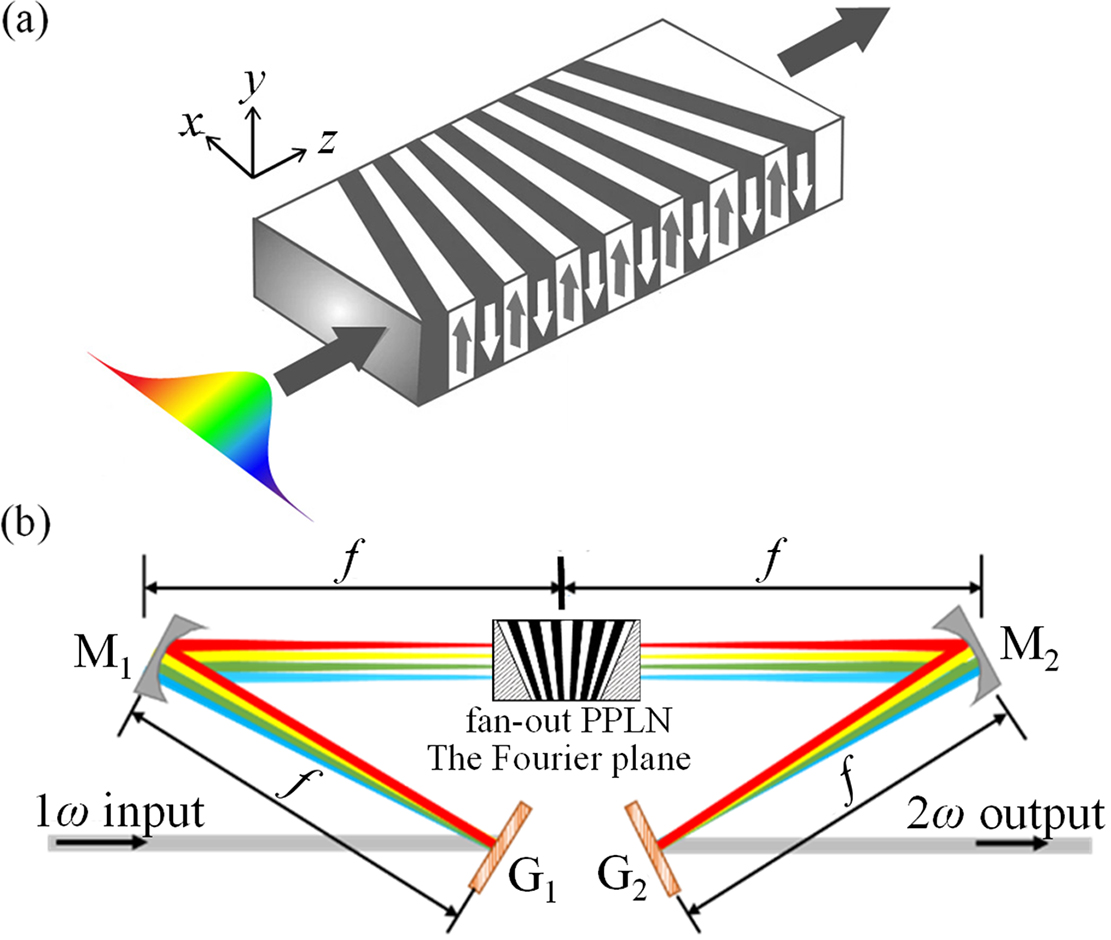
In this paper, we present a different strategy to achieve spatiotemporally-coupled phase matching, which no longer necessitates low-density diffraction gratings or thin nonlinear crystals. To break this limit of the APM scheme where the phase-matching condition exhibits angular dispersion due to the nature of birefringence, we use a quasi-phase matching (QPM) crystal in a fan-out grating structure, wherein the phase-matching condition exhibits the spatiotemporal coupling characteristic of spatial chirp , rather than angular dispersion . As schematically illustrated in Fig. 1(a), QPM crystal in a fan-out design is characterized by a linear variation of poling period along the transverse direction[18]. Accordingly, the QPM wavelength varies along the transverse direction. By transforming an ultrashort fundamental pulse into a spatially chirped beam wherein the broadband spectrum is distributed “slice by slice” onto the QPM crystal with an appropriate poling period individually [Fig. 1(b)], ultrabroadband SHG can be achieved with high efficiency. Particularly, within each transverse slice of the fan-out QPM crystal, the fundamental wave is quasi-narrowband, which fundamentally cancels high-order phase mismatch, so that thick nonlinear crystals can be used.
Sign up for Chinese Optics Letters TOC. Get the latest issue of Chinese Optics Letters delivered right to you!Sign up now
![]()
Figure 1.(a) Exaggerated view of a fan-out QPM grating; (b) schematic setup of broadband SHG in spatially chirped QPM, which consists of two diffraction gratings (G1, G2) and two concave mirrors (M1, M2) arranged in a zero-dispersion 4f configuration; f is the focal length of the concave mirrors.
2. Principle of Spatially Chirped QPM
The engineerable period of a QPM grating structure provides a new degree of freedom to optimize phase matching. Figure 1(b) presents the basic layout for ultrabroadband SHG based on a periodically poled lithium niobate (PPLN) in a fan-out grating structure. A optical setup is adopted to spatially disperse the incident wave. The frequency components of wave are angularly dispersed by G, and then focused by to a diffraction-limited line beam at the Fourier plane (i.e., the back focal plane of ). The fan-out PPLN is placed at the Fourier plane. It is worth noting that the system in our scheme is quite different from those used in pulse shaping or those in frequency-domain optical parametric amplification (FOPA)[19], wherein the signal wavelength stays the same. In our scheme, however, the aiming output () has a different wavelength from the input (). Therefore, it necessitates a precise arrangement of the system parameters to deliver a collimated output without or with least spatiotemporal coupling distortions.
We first deduce the spatiotemporal evolution of the and fields under the assumption of prefect phase matching. A spatiotemporal Gaussian-shaped pulse with a beam width of D and a Fourier-transform-limited duration of is assumed, whose complex amplitude in the spatial-spectral domain can be written as
According to Eq. (3), the local bandwidth of the spatially chirped wave can be deduced as
Under the assumption of perfect phase matching, the spatial-spectral amplitude of the laser produced in the Fourier plane can be directly written as
A comparison of Eq. (8) with Eq. (2) indicates that a collimated and distortion-free SHG output can be obtained if we adopt a diffraction grating with the half-angular dispersion coefficient of (i.e., ). In practice, we can use a diffraction grating that has a double groove density of for . After removing the angular dispersion by , the field translates into an ultrashort pulse without spatiotemporal couplings as
We next present a design of a system for the SHG of a broadband laser centered at 810 nm with a full width at half-maximum (FWHM) bandwidth of 50 nm (corresponding to in half-width at 1/e intensity). adopts a diffraction grating with a groove density of 1200 lines/mm, which provides an angular dispersion coefficient of for the laser [Fig. 2(a)]. And the second diffraction grating , with a groove density of 2400 lines/mm, provides an angular dispersion of for the laser centered at 405 nm. The two concave mirrors and have the same focal length of . The incident pulse is assumed to be a Fourier-transform-limited one in Gaussian shape, with in duration and in beam width. At the back focal plane of the concave mirror (i.e., the Fourier plane), the frequency components are dispersed in space sufficiently. In consequence, the local bandwidth is as narrow as 0.22 nm, corresponding to a pulse duration of [Fig. 2(b)]. The laser is featured by a spatial-chirp coefficient of . Assuming a perfect phase matching, a spatially chirped beam is produced, characterized by a spatial-chirp coefficient of [Fig. 2(c)] and a pulse duration of [Fig. 2(d)].
![]()
Figure 2.(a) Spatial-spectral and (b) spatiotemporal intensity profiles of the 1ω laser in the Fourier-plane; (c) spatial-spectral and (d) spatiotemporal intensity profiles of the 2ω laser in the Fourier-plane calculated under the assumption of perfect phase matching.
3. Frequency Doubling of a Spatially Chirped Beam in a Fan-Out PPLN
The combination of a fan-out PPLN and a spatially chirped fundamental provides the possibility of ultrabroadband SHG. Two key factors need to be considered deliberately. The first one is the match between the local bandwidth of the beam and the acceptance bandwidth of the QPM crystal at each transverse position. The second one is the match between the spatial-chirp coefficient of the fundamental and the period gradient of the fan-out grating.
QPM is characterized by a periodic reversal of the sign of the nonlinear coefficient to offset the accumulated phase mismatch by the material dispersion. For a PPLN in fan-out design, the varying poling period leads to a space-dependent phase mismatch as given by
With such a phase mismatch, the process of spatially chirped QPM can be numerically simulated by solving the nonlinear coupled-wave equations under the slowly varying amplitude approximation,
First, to cover a spectral range from to , the poling period range of the fan-out PPLN can be calculated as and , according to the relation,
Second, to cover the local bandwidth (0.22 nm in our simulated case) of the spatially chirped laser at each position , the length of the fan-out PPLN should be properly designed to provide an acceptance bandwidth that is wider than the local bandwidth of laser [Eq. (5)]. Under the assumptions of dispersion-free and pump nondepletion (), Eq. (11) has an approximate analytical solution as given by
Taking the central frequency component, for example, the QPM grating period can be calculated as . A PPLN length of leads to a local acceptance bandwidth of [Fig. 3(a)], which is larger than the local bandwidth (0.22 nm) of the spatially chirped beam.
![]()
Figure 3.(a) Local acceptance bandwidth of a 1 mm-long PPLN with a poling period of Λ0 = 2.81 µm; (b) optimum space-dependent poling period to match the spatial chirp of the 1ω beam (black line), in comparison with its linear approximation (red line).
Third, we move to calculate the poling period gradient of the 1 mm-long fan-out PPLN. To match the frequency gradient of the spatially chirped beam [Eq. (4)] along the axis,
Obviously, is not a strictly linear function of the transverse position . The global beam width of the spatially chirped beam is , where is the fundamental bandwidth. Since is typically much smaller than the central frequency , Eq. (16) can be approximated by Taylor expansion to the first order,
Another important parameter for a fan-out PPLN is the tilt angle of domain walls. As shown in Fig. 1(a), in a fan-out pattern, domain walls tilt away from the axis progressively toward the end of the crystal. The tilt angle of the outmost domain wall is determined as
In spatially chirped QPM, the ultrabroadband input gets frequency-doubled slice by slice at different transverse positions. The output can be regarded as the superposition of different spectral slices. The spatial overlap of the adjacent spectral slices with minor frequency shift will lead to amplitude modulations in both the spatial and spectral profiles of the spatially chirped beam at the output of the fan-out PPLN. For comparison, we numerically simulate the process of SHG in a multi-period PPLN, as shown in Fig. 4(a), which can be regarded as the prototype of a fan-out PPLN. The simulations are conducted for a fundamental without spatiotemporal couplings of 5 nm in bandwidth centered at 810 nm and 1 mm-long PPLN with three grating periods , , and . Figure 4(b) shows the second-harmonic spectra produced by each PPLN section, which clearly show that the spectra produced by the adjacent PPLN of different periods overlap with each other. Figure 4(c) depicts the spectrum produced by the multigrating PPLN with these three poling periods. It shows that the spatial overlap of the three individual spectra produced by each grating results in spectral amplitude modulation.
![]()
Figure 4.(a) Characterization of the spectral amplitude modulation arising from broadband frequency conversion using a multi-period PPLN; (b) second-harmonic spectra output from the PPLNs with the poling periods of Λ1 = 2.80 µm (magenta), Λ2 = 2.81 µm (blue), and Λ3 = 2.82 µm (green), respectively; (c) second-harmonic spectrum output from a multi-period PPLN with gratings of the three different periods calculated in (b).
We next move to characterize the performance of spatially chirped QPM in the saturation regime, where Eq. (13) is invalid. We numerically simulate the SHG process based on Eq. (11), wherein the fundamental depletion as well as media dispersion is all included. For operation around saturation the pulse incident onto is assumed to have an initial intensity of . After spatial dispersion, the spatially chirped fundamental in the Fourier plane has an intensity of . Under such an intensity, the SHG conversion efficiency reaches the maximum (77%) with a crystal length of 1 mm, as shown in Fig. 5(a). To assess the SHG efficiency of the whole system, the optical loss induced by the diffraction gratings and concave mirrors must be taken into account. Given the ultrabroadband characteristic of the fundamental and second-harmonic waves, gold-coated gratings and concave mirrors should be used, which have a typical reflectivity of for each piece, so that the overall SHG efficiency is about .
![]()
Figure 5.(a) Conversion efficiency curve calculated for the broadband SHG in a spatially chirped QPM; (b), (c), (d) spectral, temporal, and spatial intensity profiles of the 2ω pulse right at the output plane of the fan-out PPLN; (e), (f), (g) spectral, temporal, and spatial profiles of the 2ω pulse right at the output of the second diffraction grating, G2.
Figures 5(b)–5(d) present the spectral, temporal, and spatial profiles of the pulse right behind the fan-out PPLN, while Figs. 5(e)–5(g) illustrate the pulse profiles at the output of . A spatially chirped pulse has been produced [Fig. 5(b)], which exhibits obvious amplitude modulations in both the spectral [Fig. 5(b)] and spatial profiles [Fig. 5(d)]. Such amplitude modulations are induced by the local spectral clipping due to the local acceptance band and the spatial overlap of the clipped spectra produced by adjacent positions, as has been illustrated in Fig. 4. The modulation depth in the spectrum is as low as 0.05%. The pulse covers a spectral range from 370 to 440 nm [Fig. 5(b)], indicating that broadband SHG of the fundamental from 760 to 860 nm is realized. In time domain, deformation is observed in the pulse [Fig. 5(c)], which is caused by the temporal walk-off between the and pulses in the PPLN. At the output of , the pulse resorts to an ultrashort one with negligible spatiotemporal couplings [inset in Fig. 5(e)], and the pulse duration is 10.2 fs [Fig. 5(f)], which is about seven optical cycles. In the spatial profile, sidelobes appear in the output beam, as shown in the inset of Fig. 5(g), which originates from the spatial amplitude modulation imprinted onto the beam in the Fourier plane due to spatial-spectral coupling. Nevertheless, more than 96% energy is concentrated in the main beam spot.
Finally, we move to analyze the upper limit of the conversion bandwidth of our proposed scheme. Since as given by Eq. (16) is not a strictly linear function of the transverse position , the compatibility of the fan-out PPLN and the spatially chirped wave is bound to deteriorate with the increase of the fundamental bandwidth. Figure 6(a) depicts the deviation of the local poling period from the optimum poling period , and the frequency-dependent phase mismatch induced by this deviation is calculated and shown by the red line in Fig. 6(b). Due to the large phase mismatch experienced by the edge wavelength components, especially at the end of the short wavelength, the maximum wavelength range of the second-harmonic wave is 347–500 nm, as plotted by the black line in Fig. 6(b). Such a spectral range supports the production of a second-harmonic pulse centered at 405 nm with a Fourier-transform-limited duration of (full width at intensity), as illustrated in Fig. 6(c).
![]()
Figure 6.(a) Optimum space-dependent poling period Λopt (black line) calculated for the spatially chirped 1ω wave according to Eq. (
4. Conclusions
In conclusion, we theoretically demonstrate the scheme of spatially chirped QPM as well as its application in the production of a 10 fs ( optical cycles) pulse centered at 405 nm via broadband SHG with a conversion efficiency as high as 77%. The conversion efficiency and bandwidth rely on the match between the frequency gradient of the spatially chirped beam and the poling period gradient of the fan-out QPM grating, as well as the match between the local bandwidth of the spatially chirped beam and the acceptance bandwidth of QPM. For the spatially chirped fundamental, its frequency gradient and local bandwidth are primarily determined by the angular dispersion ability of the first diffraction gratings used in the zero-dispersion optical system and the diffraction divergence angle of the incident fundamental. The design principles as well as the quantitative formula for the optical system and the space-dependent poling period of the fan-out QPM grating are presented. The spatiotemporal distortions of the second-harmonic wave induced by the space-dependent spectral reshaping in the Fourier plane are also investigated, which shows that the ultrabroadband second-harmonic wave produced by a fan-out QPM grating is accompanied by spectral amplitude modulation with a modulation depth as tiny as 0.05%. Due to the spatial-spectral coupling in the Fourier plane, such spectral modulation only induces the production of weak sidelobes in the second-harmonic beam output from the optical system, while it does not degrade the temporal compression of the second-harmonic pulse. Further research shows that the theoretical limit of the conversion bandwidth for our proposed scheme is approximately 150 nm in the second-harmonic wave, which supports the production of a 4.2 fs, pulse centered at 405 nm. Such an ultrabroadband high-efficiency SHG scheme has important application for the generation of few-optical-cycle ultrashort lasers in the visible and ultraviolet spectral regions.
References

Set citation alerts for the article
Please enter your email address
© Copyright 2018-2021 | Chinese Laser Press. All Rights Reserved 沪ICP备15018463号-20