
Shijie Zhu, Pengjiang Qiu, Xinyi Shan, Runze Lin, Zhou Wang, Zuxin Jin, Xugao Cui, Guoqi Zhang, Pengfei Tian, "High-speed long-distance visible light communication based on multicolor series connection micro-LEDs and wavelength division multiplexing," Photonics Res. 10, 1892 (2022)
- Photonics Research
- Vol. 10, Issue 8, 1892 (2022)
Abstract
1. INTRODUCTION
Visible light communication (VLC) is an attractive optical wireless communication (OWC) technique for short-range communication to meet the growing demand for high-speed wireless connectivity because of its unique features, such as the ability to use an unlicensed spectrum, easy integration with solid-state lighting and, thus, low cost, high modulation bandwidth, as well as high data rate. Moreover, it can be widely used in multiple scenarios, such as indoor positioning, underwater communication, and in-vehicle wireless communication, which can effectively complement radio communication and play an important role in future 6G technology [1]. High-quality optical transmitters, such as LEDs and lasers are one of the core elements for realizing a high-performance VLC system [2]. In recent years, we have seen rapidly increasing advances in the field of VLC based on micro-LEDs, which have demonstrated impressive performances, such as optical bandwidths over 1 GHz [3] and data rates over 10 Gbps [4], thanks to the advantages of good heat dissipation, uniform current spreading, and a small RC constant brought by the small size of the device [5]. However, the small effective luminous area conversely limits its light output power (LOP), which is one of the main obstacles in its application in long-distance communication. To increase the LOP of the micro-LED, researchers have enhanced the quantum efficiency by improving the epitaxy quality and designing the device structure. The special design of the multiple quantum well structure, such as the change in the quantum barrier thickness, can effectively improve the internal quantum efficiency (IQE) or optical bandwidth of the micro-LED [6]. However, the experimental results in Ref. [6] also indicate that there is a trade-off between the LOP and the optical bandwidth under this improved method, and it is difficult to obtain the improvement of both two performances simultaneously. In addition, replacing traditional
Excitingly, specially designed parallel or series connection micro-LED structures can relax the trade-off between the LOP and the optical bandwidth as both structures can increase LOP by several times with almost no reduction in bandwidth. On one hand, it has been demonstrated that about 10 times the optical power and roughly the same bandwidth can be obtained compared to a single pixel at the same current density by using a
In this paper, we fabricated multicolor series connection micro-LED arrays with emission wavelengths of violet, blue, green, and yellow and investigated their optoelectronic properties and communication performances. All the micro-LED arrays in series exhibit a multiple increase in LOP, whereas mostly keeping a slightly reduced modulation bandwidth, thus, achieving a higher signal-to-noise ratio (SNR). The micro-LED arrays with emission wavelengths of 400, 451, 509, and 556 nm achieved data rates of 5.71, 4.86, 4.39, and 0.82 Gbps, respectively. The proof-of-concept WDM system was demonstrated with an aggregate data rate of 15.78 Gbps under a transmission distance of 13 m using bit/power loading OFDM, which was the best data rate-distance product performance for the LED-based VLC to the best of our knowledge as shown in Table 1 [12–20].
Summary of LED-Based WDM-OWC Systems with the Aggregate Data Rate over 10 Gbps in Recent Years
| LED Type | System Type | Aggregate | Distance | Data Rate × | Performance of the | Reference |
|---|---|---|---|---|---|---|
| LED (R) + μLEDs (GB) | Real WDM | 11.28 Gbps | 1.5-m free space | 16.92 Gbps m | 7.09 Gbps m (B) | [ |
| 3.84 Gbps m (G) | ||||||
| 6 Gbps m (R) | ||||||
| LEDs (RGBYC | Proof of concept | 15.17 Gbps | 1.2-m underwater | 18.2 Gbps m | 3.76 Gbps m (B) | [ |
| 3.74 Gbps m (C) | ||||||
| 3.72 Gbps m (G) | ||||||
| LEDs (RGBY) | Proof-of-concept | 19.66 Gbps | 1.6-m free space | 31.46 Gbps m | 8.35 Gbps m (B) | [ |
| Real WDM | 16.92 Gbps | 1.6-m free space | 27.07 Gbps m | 8.42 Gbps m (G) | ||
| 8.21 Gbps m (R) | ||||||
| LEDs (eight color) | Proof of concept | 20.09 Gbps | 1.2-m underwater | 24.11 Gbps m | 3.46 Gbps m (B) | [ |
| 3.29 Gbps m (G) | ||||||
| 3.79 Gbps m (R) | ||||||
| Mini-LEDs (tricolor) | Proof of concept | 16.6 Gbps | 2-m free space | 33.2 Gbps m | 14 Gbps m (B) | [ |
| 14 Gbps m (C) | ||||||
| 5.2 Gbps m (G) | ||||||
| LEDs (eight color) | Proof of concept | 24.25 Gbps | 1.2-m free space | 29.1 Gbps m | 3.98 Gbps m (B) | [ |
| 3.91 Gbps m (G) | ||||||
| 4.15 Gbps m (R) | ||||||
| LEDs (tricolor) + μLEDs (five color) | Proof of concept | 25.2 Gbps | 0.25-m free space | 6.3 Gbps m | 1.21 Gbps m (V) | [ |
| 1.09 Gbps m (B) | ||||||
| 1.04 Gbps m (G) | ||||||
| μLEDs (UVA + UVB + UVC) | Real WDM | 10.32 Gbps | 0.5-m free space | 5.16 Gbps m | 1.57 Gbps m (UVA) | [ |
| Proof of concept | 11.48 Gbps | 0.5-m free space | 5.74 Gbps m | 1.51 Gbps m (UVB) | ||
| 2.08 Gbps m (UVC) | ||||||
| LEDs (RGB) | Proof of concept | 3.1 Gbps | 5-m fiber | 15.5 Gbps m | 60 Gbps m (B) | [ |
| 2 Gbps | 100-m fiber | 200 Gbps m | 60 Gbps m (G) | |||
| 80 Gbps m (R) | ||||||
| μLEDs (VBGY) | Proof of concept | 15.78 Gbps | 13-m free space | 205.1 Gbps m | 74.23 Gbps m (V) | This paper |
| 63.18 Gbps m (B) | ||||||
| 57.07 Gbps m (G) |
μLEDs: micro-LEDs.
Real WDM: dichroic mirrors and optical color filters are utilized to separate WDM channels.
VRGBYC: violet, red, green, blue, yellow, and cyan.
Proof-of-concept: an ideal WDM system to directly accumulate the data rates measured individually for each color channel.
Sign up for Photonics Research TOC. Get the latest issue of Photonics Research delivered right to you!Sign up now
2. SERIES CONNECTION MICRO-LED ARRAYS
A. Design and Fabrication
The fabrication process of series connection micro-LED arrays with different emission wavelengths was started by deposition of 40-nm indium tin oxide (ITO) on the epitaxial layers grown on the
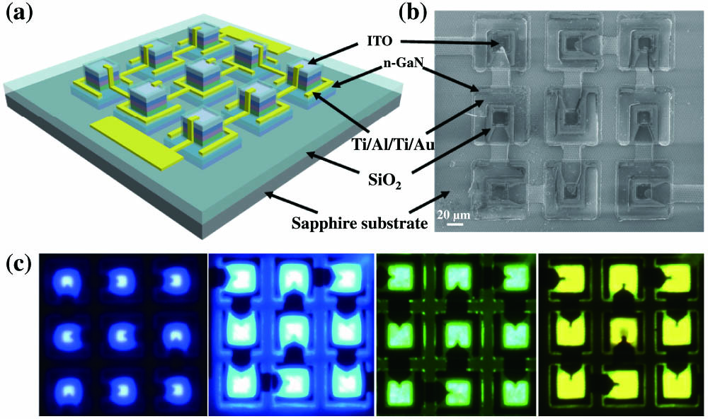
Figure 1.(a) Schematic of GaN-based series connection micro-LED array. (b) Plan-view SEM image of the 20-μm blue GaN-based series connection micro-LED array. (c) Plan-view optical micrograph images of the series connection micro-LED arrays.
B. Optical and Electrical Characteristics
The optical and electrical characteristics of the series connection micro-LED arrays were measured after the chips have been packaged on printed circuit boards. The curves of current versus voltage of the series arrays (B1, B4, B6, and B9 corresponding to 1, 4, 6, and 9 blue pixels, respectively) with different emission wavelengths described above are shown in Fig. 2. As can be seen from Fig. 2, the driving voltage of micro-LED arrays with the same number of pixels at longer wavelength tends to be higher at the same bias current, which may be due to the difference in epitaxial materials and structures. Taking the blue micro-LED array as an example, as the number of pixels increases, the forward bias voltages (3.2, 13.1, 19.4, and 32.0 V) of the series arrays corresponding to a bias current of 1 mA will increase accordingly (1, 4, 6, and 9 pixels). Additionally, the differential resistance of the device under the same bias current will increase as the number of pixels increases. The impact of the RC effect on the modulation bandwidth of the series connection micro-LED array is under investigation due to the discovery of the negative capacitance effect under the forward current.
![]()
Figure 2.Current versus voltage curves for (a) 20-μm violet, (b) 20-μm blue, (c) 20-μm green, and (d) 40-μm yellow micro-LED arrays with 1, 4, 6, and 9 pixels in series, respectively.
Series connection is an effective way to boost the LOP of the micro-LED but at the cost of the increased driving voltage. The LOPs of the series connection micro-LED arrays under different current densities are shown in Fig. 3, which are measured by using a lens to focus the light emitted by the array into an optical power meter (Thorlabs PM100D). The LOPs for the 20-μm blue series micro-LED arrays with 1, 4, 6, and 9 pixels under the current density of
![]()
Figure 3.Light output power versus current density curves for (a) 20-μm violet, (b) 20-μm blue, (c) 20-μm green, and (d) 40-μm yellow micro-LED arrays with 1, 4, 6, and 9 pixels in series, respectively.
To confirm the wavelength separation of the micro-LED arrays, which are expected to realize WDM communication, we measured the electroluminescence (EL) spectra of the devices under different current densities as shown in Figs. 4(a)–4(d). The EL spectra of the devices under the communication test conditions are shown in Fig. 4(e). Among them, the peak wavelengths of violet, blue, and green light are 400, 451, and 509 nm, respectively. Due to the existence of stress-induced polarization fields and band-filling effects in the multiple quantum wells with high indium component, the emission wavelength of yellow light has a significant blueshift with the increase in current density [21] as shown in Fig. 4(d), and, thus, the peak wavelength of yellow light is selected to be 556 nm at a lower current density of
![]()
Figure 4.Emission spectra of the (a) 20-μm
3. MODULATION BANDWIDTH
Modulation bandwidth of the light emitter is one of the critical parameters in VLC applications. In this paper, a vector network analyzer (VNA, PicoVNA 106) was adopted to measure the frequency responses of the micro-LEDs. The alternating current (AC) frequency sweep signal from the VNA plus a direct current (DC) signal through a bias-tee (Pasternack PE1615, 0.01–6 GHz) was loaded to the micro-LED to measure the frequency response. The used detector here was a Si avalanche photodiode (APD, Hamamatsu C5658) with a 1-GHz bandwidth. According to Shannon–Hartley theorem
Performances of Blue Micro-LED Arrays with Different Pixel Sizes and Different Operating Current Densities
| Pixel Size | Stable Operating Current Density/LOP | Achieved | LOP·Bandwidth |
|---|---|---|---|
| 40 μm ( | 84.2 MHz | 1160 mW MHz | |
| 30 μm ( | 122.4 MHz | 1468 mW MHz | |
| 20 μm ( | 214.4 MHz | 2041 mW MHz | |
| 10 μm ( | 360.7 MHz | 957.6 mW MHz |
In addition, operating at the same injection current density, the
![]()
Figure 5.(a) The modulation bandwidths versus pixel numbers of the GBYV micro-LEDs under the same injection current density. (b) The frequency responses of the series-biased GBYV micro-LED arrays under the specific current density for VLC measurement. (c) The microwave reflectance (S11) parameters of blue micro-LED arrays with different numbers of pixels in series under the current density of
4. VLC MEASUREMENT
A. Experiment Setup
The fabricated series connection micro-LED arrays with larger LOPs are expected to achieve more promising VLC performances at a long distance compared to that of the single-pixel device. In this paper, a proof-of-concept WDM system with a 13-m free-space link was established to experimentally test the long-distance data transmission characteristics of the multicolor series connection micro-LED arrays as shown in Fig. 6. Using a homemade program in MATLAB, the digital OFDM data with a bit and power loading algorithm was generated and loaded into the arbitrary waveform generator (AWG, Tektronix AWG710B, 4.2 GSa/s), which plays a role of the high-speed and high-precision digital-to-analog converter. The output port of the AWG was connected to an electrical amplifier (EA, Mini-Circuits ZHL-2-12+) with a typical gain of 26 dB. Through a bias-tee (Pasternack PE1615, 0.01–6 GHz), the bipolar waveform from EA was biased by a DC signal from a DC source (Yokogawa GS610) to yield the positive signal, which was a must for intensity modulation in optical communication. The unipolar OFDM signal was fed into the series-biased micro-LED array chip to emit modulated light, which was collimated by an aspheric condenser lens (Thorlabs ACL5040U-A, Ø50 mm,
![]()
Figure 6.Schematic of the experimental setup for the multicolor series connection micro-LED arrays-based long-distance VLC system.
B. Modulation Scheme
The VLC system has a decay response in the frequency domain resulting in the nonuniform SNR distribution. Therefore, DC-biased optical OFDM (DCO-OFDM) modulation with the bit and power loading method is used in this paper to allocate more bits on each subcarrier to approach Shannon capacity, and its block diagram is shown in Fig. 6. The binary sequences are mapped into
Before implementing the processes above, the binary phase shift keying symbols with identical subcarrier power ought to be sent first to carry out the SNR estimation and the frequency response of the overall system is obtained. At a target BER, afterward, bit loading method could adaptively allocate graded QAM orders as an initial allocation according to the SNR distribution, which is derived from the error vector magnitude between the transmitted and the received constellations. However, the initial allocation has a considerable current margin, which is the gap between the estimated subcarriers SNR and required SNR for current allocated QAM order. Current margin is used to evaluate the degree of wasted energy. The allocated bits amount will be improved when the current margin is reduced. Hence, the power loading method is adopted to optimize the SNR margin and update the bit allocation by adjusting the power ratio on the subcarriers according to the Levin–Campello algorithm [24]. It is noted that the little variation of power on the subcarriers leads to the equivalent variation of SNR in this paper. Jointly employing the bit and power loading, the spectral efficiency will be improved. Based on the updated bit allocation, the data transmission rate is calculated by [17]
C. Results and Discussion
The VLC performances of the GBYV series connection micro-LED arrays were conducted individually based on the experiment setup and modulation scheme described above. The driving current and modulation depth (
![]()
Figure 7.(a) Light output powers of the 20-μm
![]()
Figure 8.SNR distributions, bit allocations, and power ratios versus frequency for (a) 400-nm, (b) 451-nm, (c) 50-nm, and (d) 556-nm channels.
The average numbers of bits per symbol are 4.7578, 4.0493, 4.1809, and 1.6368 for 400-, 451-, 509-, and 556-nm micro-LED arrays, resulting in the achievable data rates of 5.71, 4.86, 4.39, and 0.82 Gbps, respectively. Therefore, corresponding to an ideal WDM implementation without considering the channel cross talk, an aggregate data rate of 15.78 Gbps is achieved, which would be indeed decreased in real scenarios. The power spectra with the use of pre-equalization for the GBYV chips are shown in Fig. 9. Certainly, a decrease in the SNR and data rate for each channel will be observed in a real WDM demonstration with dichroic mirrors and optical filters due to the channel cross talk induced by the spectral overlap. In this paper, the violet, blue, green, and yellow micro-LED channels can be separated by using 420-, 490-, and 550-nm long pass dichroic mirrors, respectively. Taking the blue micro-LED channel as an example, the performance loss of the channel was evaluated by adding a 420 nm long pass filter at the receiver. The data rate of the blue micro-LED channel would be reduced by 7.4% from 4.86 to 4.5 Gbps under the same transmission distance. In addition, for green and yellow micro-LED channels, the data rate loss is more severe due to more spectral overlap. Figure 10(a) depicts the constellation plots for the 400-nm channel including the 4, 8, 16, 32, 64, and 128 QAMs. To verify the superiority of series connection micro-LED array in the long-distance VLC application, the SNR distributions of the violet single-pixel and series connection devices under the same injection current density of
![]()
Figure 9.Power spectra for (a) 400-nm, (b) 451-nm, (c) 509-nm, and (d) 556-nm channels.
![]()
Figure 10.(a) Constellation plots for the 400-nm channel including the 4, 8, 16, 32, 64, and 128 QAMs. (b) SNR distributions of the 20-μm violet single-pixel and series connection devices under the current density of
5. CONCLUSION
In this paper, we prepared the multicolor series connection micro-LED array devices and experimentally investigated their superiority in long-distance VLC applications. The designed
References
[1] M. Katz, I. Ahmed. Opportunities and challenges for visible light communications in 6G. 2nd 6G Wireless Summit (6G SUMMIT), 1-5(2020).
[2] S. Zhu, X. Chen, X. Liu, G. Zhang, P. Tian. Recent progress in and perspectives of underwater wireless optical communication. Prog. Quantum Electron., 73, 100274(2020).
[3] A. Rashidi, M. Monavarian, A. Aragon, A. Rishinaramangalam, D. Feezell. Nonpolar
[4] E. Xie, R. Bian, X. He, M. S. Islim, C. Chen, J. J. D. McKendry, E. Gu, H. Haas, M. D. Dawson. Over 10 Gbps VLC for long-distance applications using a GaN-based series-biased micro-LED array. IEEE Photon. Technol. Lett., 32, 499-502(2020).
[5] P. Tian, J. J. McKendry, Z. Gong, B. Guilhabert, I. M. Watson, E. Gu, Z. Chen, G. Zhang, M. D. Dawson. Size-dependent efficiency and efficiency droop of blue InGaN micro-light emitting diodes. Appl. Phys. Lett., 101, 231110(2012).
[6] Z. Yuan, Y. Li, X. Lu, Z. Wang, P. Qiu, X. Cui, P. Tian, Q. Wang, G. Zhang. Investigation of modulation bandwidth of InGaN green micro-LEDs by varying quantum barrier thickness. IEEE Trans. Electron Devices(2022).
[7] Y.-H. Chang, Y.-M. Huang, F.-J. Liou, C.-W. Chow, Y. Liu, H.-C. Kuo, C.-H. Yeh, W. H. Gunawan, T.-Y. Hung, Y.-H. Jian. 2.805 Gbit/s high-bandwidth phosphor white light visible light communication utilizing an InGaN/GaN semipolar blue micro-LED. Opt. Express, 30, 16938-16946(2022).
[8] Y.-H. Chang, Y.-M. Huang, W. H. Gunawan, G.-H. Chang, F.-J. Liou, C.-W. Chow, H.-C. Kuo, Y. Liu, C.-H. Yeh. 4.343-Gbit/s green semipolar (20-21)
[9] M. Monavarian, A. Rashidi, D. Feezell. A decade of nonpolar and semipolar III-nitrides: a review of successes and challenges. Phys. Status Solidi A, 216, 1800628(2019).
[10] H.-Y. Lan, I.-C. Tseng, Y.-H. Lin, G.-R. Lin, D.-W. Huang, C.-H. Wu. High-speed integrated micro-LED array for visible light communication. Opt. Lett., 45, 2203-2206(2020).
[11] G.-R. Lin, H.-C. Kuo, C.-H. Cheng, Y.-C. Wu, Y.-M. Huang, F.-J. Liou, Y.-C. Lee. Ultrafast 22 green micro-LED array for optical wireless communication beyond 5 Gbit/s. Photon. Res., 9, 2077-2087(2021).
[12] H. Chun, S. Rajbhandari, G. Faulkner, D. Tsonev, E. Xie, J. J. D. McKendry, E. Gu, M. D. Dawson, D. C. O’Brien, H. Haas. LED based wavelength division multiplexed 10 Gb/s visible light communications. J. Lightwave Technol., 34, 3047-3052(2016).
[13] Y. Zhou, X. Zhu, F. Hu, J. Shi, F. Wang, P. Zou, J. Liu, F. Jiang, N. Chi. Common-anode LED on a Si substrate for beyond 15 Gbit/s underwater visible light communication. Photon. Res., 7, 1019-1029(2019).
[14] R. Bian, I. Tavakkolnia, H. Haas. 15.73 Gb/s visible light communication with off-the-shelf LEDs. J. Lightwave Technol., 37, 2418-2424(2019).
[15] F. Hu, G. Li, P. Zou, J. Hu, S. Chen, Q. Liu, J. Zhang, F. Jiang, S. Wang, N. Chi. 20.09-Gbit/s underwater WDM-VLC transmission based on a single Si/GaAs-substrate multichromatic LED array chip. Optical Fiber Communications Conference and Exhibition (OFC), M3I.4(2020).
[16] X. Liu, Z. Wei, M. Li, L. Wang, Z. Liu, C. Yu, L. Wang, Y. Luo, H. Fu. Experimental investigation of 16.6 Gbps SDM-WDM visible light communication based on a neural network receiver and tricolor mini-LEDs. Opt. Lett., 46, 2888-2891(2021).
[17] F. Hu, S. Chen, G. Li, P. Zou, J. Zhang, J. Hu, J. Zhang, Z. He, S. Yu, F. Jiang, N. Chi. Si-substrate LEDs with multiple superlattice interlayers for beyond 24 Gbps visible light communication. Photon. Res., 9, 1581-1591(2021).
[18] P. Qiu, S. Zhu, Z. Jin, X. Zhou, X. Cui, P. Tian. Beyond 25 Gbps optical wireles communication using wavelength division multiplexed LEDs and micro-LEDs. Opt. Lett., 47, 317-320(2022).
[19] D. M. Maclure, J. J. McKendry, M. S. Islim, E. Xie, C. Chen, X. Sun, X. Liang, X. Huang, H. Abumarshoud, J. Herrnsdorf, E. Gu, H. Haas, M. D. Dawson. 10 Gbps wavelength division multiplexing using UV-A, UV-B, and UV-C micro-LEDs. Photon. Res., 10, 516-523(2022).
[20] J. Shi, Y. Zhou, N. Chi, L. Xiong, J. Luo. Gigabit LED-based visible light transparent transmission from free-space to a 100-m ultra-large effective area pure silica fiber. Microw. Opt. Technol. Lett., 60, 13-18(2018).
[21] C. Du, Z. Ma, J. Zhou, T. Lu, Y. Jiang, P. Zuo, H. Jia, H. Chen. Enhancing the quantum efficiency of InGaN yellow-green light-emitting diodes by growth interruption. Appl. Phys. Lett., 105, 071108(2014).
[22] H. Chun, S. Rajbhandari, G. Faulkner, E. Xie, J. J. D. McKendry, E. Gu, M. D. Dawson, D. O’Brien. Optimum device and modulation scheme selection for optical wireless communications. J. Lightwave Technol., 39, 2281-2287(2021).
[23] J.-L. Yen, X.-N. Chen, K.-L. Chi, J. Chen, J.-W. Shi. 850 nm vertical-cavity surface-emitting laser arrays with enhanced high-speed transmission performance over a standard multimode fiber. J. Lightwave Technol., 35, 3242-3249(2017).
[24] F. Hu, S. Chen, Y. Zhang, G. Li, P. Zou, J. Zhang, C. Shen, X. Zhang, J. Hu, J. Zhang, Z. He, S. Yu, F. Jiang, N. Chi. High-speed visible light communication systems based on Si-substrate LEDs with multiple superlattice interlayers. PhotoniX, 2, 16(2021).


Set citation alerts for the article
Please enter your email address

© Copyright 2018-2021 | Chinese Laser Press. All Rights Reserved 沪ICP备15018463号-20