Yongqiu Zheng, Yongfeng Ren, Panlong An, Chengqun Chu, Xiaofeng Li, Chenyang Xue, Jun Liu, Shubin Yan. Wide dynamic range experiments on a resonator fiber optic gyro based on closed-loop frequency locking technique[J]. Chinese Optics Letters, 2015, 13(2): 020601
Copy Citation Text
Wide dynamic range is an important index of the resonator fiber optic gyro (RFOG). The dynamic range is related to the parameters of the fiber ring resonator (FRR). After adopting the appropriate parameters, the resonant curve of a FRR and the synchronous demodulated curve are measured. Based on the closed-loop frequency locking technique, the wide dynamic range is obtained, while the linearity is guaranteed. The experiment’s results show that the dynamic range is with less than 1% nonlinearity, and that the bias stability is 0.04 deg/s over 2000 s. This Letter demonstrates the scheme for a RFOG with a wide dynamic range.
A resonator fiber optic gyro (RFOG) based on the Sagnac effect has been proposed and investigated during the past few decades. Compared with the traditional spinning mass gyros, the RFOG has significant advantages, such as high accuracy and reliability, a short warm-up time, and a light weight[1,2]. Compared with the interferometric fiber optic gyro (IFOG), the RFOG can achieve the same grade performance with a fiber coil that is shorter in length[3,4]. However, there are still many techniques that have not reached a breakthrough. According to public literature, the wide dynamic ranges of RFOGs are generally around 100 deg/s, which fails to meet the tactical grade application requirement[5–7].
The fiber ring resonator (FRR) is one of the key elements of a RFOG[8]. The rotation rate can be obtained by detecting the resonance frequency difference between the counterpropagating light beams that are transmitted in the FRR. The wide dynamic range of the RFOG is determined by its resonant characteristics. There are many parameters that contribute to the determination of the resonant characteristics, including, but not limited to, the length of the FRR, the coupling coefficient of the couplers, and propagation loss. Most researchers optimize the parameters of the FRR to improve the sensitivity and bias stability of the RFOG. Shupe analyzed the relationship between the sensitivity of the gyro and the optimal length of the fiber[2]. Iwatsuki et al. presented a different description of sensitivity, emphasizing the impact of the resonator length on sensitivity[9]. Hotate et al. achieved a bias drift of 35 deg/h with an integration time of 1 s by suppressing polarization fluctuation[10]. Jin et al. obtained the dynamic range value of and a bias drift of 0.29 deg/s over 10 s using the digital detection technique[11]. Clearly, all of the above optimizations only considered the sensitivity of gyro, while the full range of gyro was not taken into account.
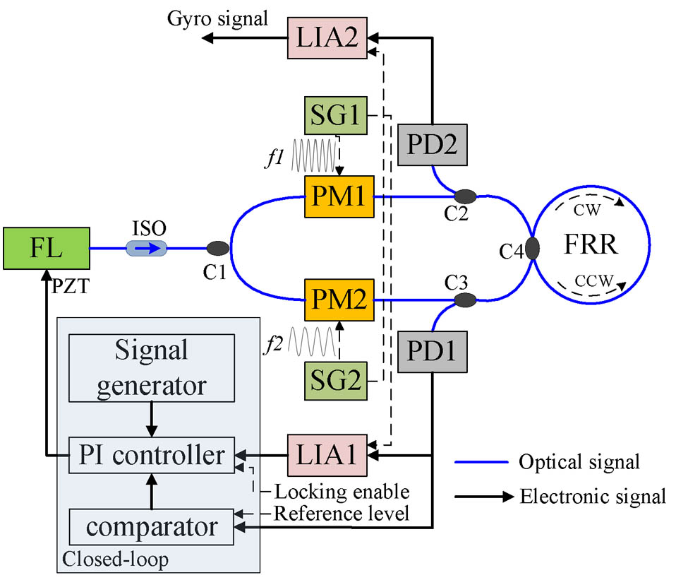
In this Letter, a scheme for a RFOG with a wide dynamic range is investigated and demonstrated. The schematic configuration of the RFOG is shown in Fig. 1. A distributed feedback fiber laser (FL) with a center wavelength of 1550 nm and a spectrum linewidth of 1 kHz is used. Two phase modulators (PM1 and PM2), each with a half-wave voltage of less than 4 V, are employed to modulate the output light from the laser. PD1 and PD2 are two InGaAs positive-intrinsic-negative (PIN) photodetectors (PDs), the responsivities of which are both 7 V/mW. As the core-sensing element, the FRR is designed with a diameter of 0.15 m using a 12-m-length polarization maintaining fiber. As a result, the theory scale-factor of this system is , given by where is the diameter of the FRR, is the light wavelength, and is the angular velocity rate[1,12].
Sign up for Chinese Optics Letters TOC. Get the latest issue of Chinese Optics Letters delivered right to you!Sign up now
The coupling coefficients of the couplers C1, C2, C3, and C4 are all 0.5. The insertion losses of C1, C2, C3, and C4 are all 0.3 dB. The propagation loss of the FRR is 0.006 dB. The output intensity of the FL is 10 mW. The integration time of the system is 10 s. Therefore, the shot-noise-limited sensitivity is estimated to be [3,9]. PM1 and PM2 are driven by sinusoidal waveforms from signal generators (SG1 and SG2). Note that the modulation frequencies and are diversified in order to attenuate any backscattering errors[13]. The counter-clockwise (CCW) and clockwise lightwaves emitting from the FRR are sensed by PD1 and PD2, respectively. The demodulated signal from lock-in amplifier 1 (LIA1) is used to track the frequency of the FL to the CCW resonance frequency through the closed-loop servo controller. At the same time, the demodulated signal from LIA2 is used as the open-loop output of the rotation rate.
Taking the light transmitted clockwise as an example, the full width at half-maximum (FWHM) is 4.94 MHz. It is observed from the resonance curve, such as the one in Fig. 2(a). The synchronous demodulated curve is shown in Fig. 2(b). The linear region bandwidth is , and is symmetrically distributed as the resonance frequency point. The corresponding angular velocity range, obtained using Eq. (1), is .
In order to confirm that the scale factor accuracy of the gyro can meet the requirements for tactical application, the nonlinearity of the linear region must be less than 0.01. Thus, the wide dynamic range bandwidth is limited to with a slope of 367 mV/MHz. This will be assumed to be the full range of the RFOG.
To track the resonance frequency of the FRR, a closed-loop servo controller is applied. Figure 3 shows how to lock the laser frequency to the resonance frequency of the FRR[13,14]. With a ramp voltage signal, the frequency of the laser sweeps linearly. An external reference level is presented, and the voltage comparator is applied. The resonance valley judgment signal becomes low when the output of the PD is less than the presented reference level. The resonance curve, demodulated curve, and resonance valley judgment are synchronous. Thus, the proportion integral (PI) controller only works in the linear region of demodulated curve. When the frequency locking enable signal is highly active, the output of the PD is slowly swept into the resonance valley. Then, as the resonance valley judgment signal becomes low, the PI controller starts to control the light frequency, in order to track the resonance frequency of the FRR. After the frequency locking, the output of the PD is at the minimum constant value, and the demodulation signal is approximate to the zero level.
Figure 4 shows the static test result of the RFOG. With the integration time of 10 s, the bias stability is 0.04 deg/s over 2000 s. Meanwhile, the gyro outputs are tested under different rotation rates. The gyro outputs as shown in Fig. 5(a) are obtained by subtracting the time cost by the rotation rate change according to the acceleration. The result shows that the rotation rate varies from 0 to 480 deg/s with a step of 60 deg/s. Each rate is for 100 s when the gyro is at rest and the output is close to zero. For each different rate, there are two rotation directions, and the outputs are nearly equal but opposite. The average values of the output data under each rotation rate are illustrated in Table 1. The linear fitting line is shown in Fig. 5(b). Its nonlinearity is less than 1% in the dynamic range of . It is noteworthy that, in this experiment, the FRR is isolated from external environmental factors, including temperature, vibration, and sound. Therefore, the influence on the gyro output due to external environmental factors is reduced and the experimental results are not affected by the outside environment. However, there is still a lot of work to be done to achieve a wide dynamic range beyond 500 deg/s. At the same time, to improve linearity and sensitivity, more effective countermeasures must be adopted to suppress optical noise such as Rayleigh backscattered noise or optical Kerr noise, and to reduce the temperature drift[15–18].
In conclusion, the RFOG system with a wide dynamic range is successfully constructed by adopting the appropriate parameters of the FRR. The experimental results from using a wide dynamic range are obtained. These results are useful in applying the RFOG to engineering. However, a resonator micro-optic gyro (RMOG) based on the waveguide resonator is the development trend for the future[19,20]. Because the resonant characteristics of the RMOG are similar to that of the RFOG, the experimental results can also serve as guide in the investigation.
Yongqiu Zheng, Yongfeng Ren, Panlong An, Chengqun Chu, Xiaofeng Li, Chenyang Xue, Jun Liu, Shubin Yan. Wide dynamic range experiments on a resonator fiber optic gyro based on closed-loop frequency locking technique[J]. Chinese Optics Letters, 2015, 13(2): 020601