1State Key Laboratory for Modern Optical Instrumentation, Center for Optical & Electromagnetic Research, College of Optical Science and Engineering, International Research Center for Advanced Photonics, Zhejiang University, Hangzhou 310058, China
2Ningbo Research Institute, Zhejiang University, Ningbo 315100, China
An ultrahigh-Q silicon racetrack resonator is proposed and demonstrated with uniform multimode silicon photonic waveguides. It consists of two multimode straight waveguides connected by two multimode waveguide bends (MWBs). In particular, the MWBs are based on modified Euler curves, and a bent directional coupler is used to achieve the selective mode coupling for the fundamental mode and not exciting the higher-order mode in the racetrack. In this way, the fundamental mode is excited and propagates in the multimode racetrack resonator with ultralow loss and low intermode coupling. Meanwhile, it helps achieve a compact 180° bend to make a compact resonator with a maximized free spectral range (FSR). In this paper, for the chosen 1.6 μm wide silicon photonic waveguide, the effective radius of the designed 180° bend is as small as 29 μm. The corresponding FSR is about 0.9 nm when choosing 260 μm long straight waveguides in the racetrack. The present high-Q resonator is realized with a simple standard single-etching process provided by a multiproject wafer foundry. The fabricated device, which has a measured intrinsic Q-factor as high as , is the smallest silicon resonator with a Q-factor.
1. INTRODUCTION
In the past years, silicon photonics has been a promising platform for photonic integrated circuits because of its high complementary metal-oxide semiconductor (CMOS) compatibility as well as high integration density [1,2]. Meanwhile, compact devices are usually desired and can be realized on a silicon-on-insulator (SOI) platform because of the high refractive index contrast between the silicon core and the silica cladding. In particular, the microring resonators (MRRs) with ultrahigh-Q factors and compact sizes have been in great demand in many fields, including microwave filters [3,4], lasers [5], sensors [6,7], and nonlinear/quantum optics [8–10]. However, the Q-factor is usually limited by scattering losses introduced by the rough sidewalls due to fabrication imperfections [11].
Tremendous effort has been devoted to improving the Q-factor of silicon photonic resonators [12–19]. For example, a suspended MRR with an intrinsic of and a small radius of 9 μm was demonstrated with two-step electron beam lithography (EBL) and inductively coupled plasma (ICP) reactive ion etching (RIE) processes [12]. In particular, a post-exposure bake was employed to reflow the photoresist and thus reduce the sidewall roughness. The sidewalls can also be smoothed using etchless fabrication processes with thermal oxidation, and the demonstrated MRRs with the shaped ridge waveguides have intrinsic Q-factors as high as [13] and [14]. However, the thermal oxidation process is not standard for silicon photonics and usually unavailable for foundries. Recently, using multimode ridge waveguides was demonstrated to reduce the sidewall scattering loss to achieve ultrahigh-Q factors. For instance, a silicon MRR based on multimode ridge waveguides assisted with a 90° single-mode strip waveguide bend was demonstrated with an ultrahigh-Q of [15]. However, the resonator length is as large as 37.7 mm; thus, the free spectral range (FSR) is limited to as small as 17.1 pm. In Refs. [3,16], waveguide tapers were demonstrated to connect straight multimode ridge waveguides and 180° bent single-mode waveguides, which reduces the resonator length to 3164–2025 μm, and increased the FSR to 0.208–0.325 nm. However, it is difficult to further shrink the resonator because long tapers are needed (e.g., 50 μm), and the effective bending radius for the resonator is still large. Furthermore, the tapers and the single-mode waveguide bend will introduce notable scattering losses because they are narrow, and strong scattering happens at their sidewalls. A silicon multimode MRR with a large radius of 450 μm was proposed using uniform strip waveguides with a cross section of μ in Ref. [17]. For this MRR, it is also difficult to reduce the bending radius due to intermode coupling. For the demonstrated MRR, the achieved Q-factor is about , while the FSR is still as small as 0.16 nm.
In this paper, we propose and demonstrate an ultrahigh-Q silicon racetrack resonator based on a uniform multimode silicon photonic waveguide, which consists of two multimode straight waveguides and two multimode waveguide bends (MWBs) based on modified Euler curves. As a result, it helps to achieve a compact 180° bend to make a compact resonator with a maximized free spectral range. A bent directional coupler is used to achieve the selective mode coupling for the fundamental mode and not exciting the higher-order mode in the racetrack. With this design, the fundamental-mode is excited and propagates in the multimode racetrack resonator with ultralow loss and low intermode coupling. As an example, the racetrack resonator is made of a 1.6-μm-wide uniform silicon photonic waveguide consisting of 180° MWBs with an effective radius as small as 29 μm. The designed high-Q resonator is realized with a simple standard single-etching process provided by a multiproject wafer foundry. For the fabricated racetrack resonator, the loaded Q-factor is about , and the FSR is about 0.9 nm, which can be improved by reducing the length of the straight sections. The intrinsic Q-factor of the present resonator is about , which is estimated from the Lorentz curve fitting, and the corresponding waveguide loss is estimated to be about 0.3 dB/cm. It is expected that the present silicon photonic resonators will play a very important role in many applications, including microwave photonic filters and optical sensors.
Sign up for Photonics Research TOC. Get the latest issue of Photonics Research delivered right to you!Sign up now
2. STRUCTURE AND DESIGN
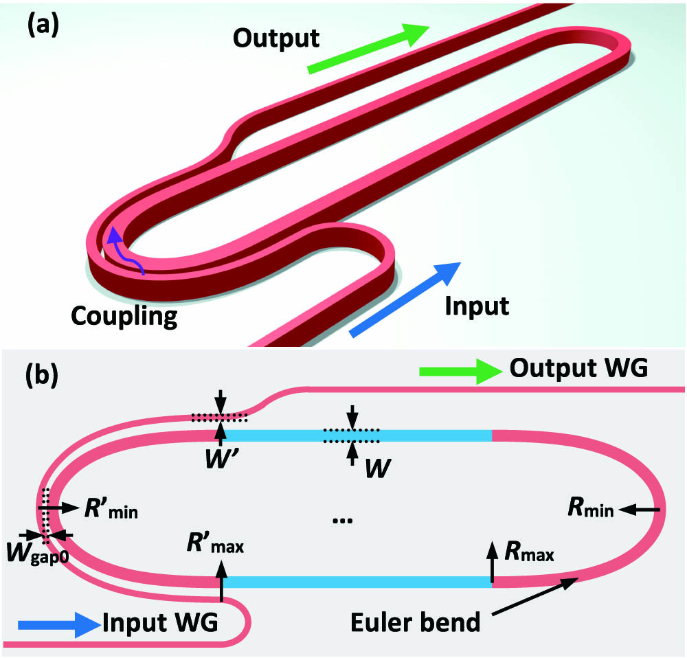
Figures 1(a) and 1(b) show the three-dimensional (3D) view and the top view of the present ultrahigh-Q silicon racetrack resonator based on a uniform multimode silicon photonic waveguide. There are two multimode straight waveguides and two multimode waveguide bends based on modified Euler curves. To not excite the higher-order mode in the racetrack, a bent directional coupler is used so that the mode coupling happens between the fundamental modes in the narrow access waveguide and the wide racetrack waveguide.
Figure 1.Schematic configurations of the proposed ultrahigh-Q MRR. (a) 3D view and (b) top view.
Here, a silicon-on-insulator (SOI) wafer with a 220 nm thick silicon core layer and 2 μm thick buried-oxide layer is used. The operation wavelength is around 1550 nm, and the corresponding refractive index of silicon and silica is and , respectively. Devices were designed for the transverse electric (TE) polarization. Figure 2(a) shows the cross section of an SOI optical waveguide. For the 220 nm thick SOI strip waveguide, the core width should be less than 450 nm to be single mode for TE polarization. As is well known, the power attenuation in the silicon racetrack resonators is mainly from the propagation loss as well as the bending loss. Since the propagation loss is mainly dominated by scattering from the rough waveguide sidewalls, in this paper we determine the waveguide core width optimally, according to the dependence of the scattering loss on the core width.
Figure 2.(a) Cross section of the SOI waveguide. (b) Mode field distribution at a waveguide width μ. (c) Calculated transmission loss as the waveguide core width increases with different mean deviation at the wavelength of 1550 nm.
Here, we calculate the scattering loss of the optical waveguide by using the 3D volume current method [20]. In this model, the radiation loss introduced by the nonuniformity of the refractive index due to the sidewall roughness is modeled as an equivalent polarization volume current source. The power spectrum is then related to the autocorrelation function of the roughness profile by a Fourier transform. Finally, the total radiated power per unit length due to the current source is calculated as where is the outwardly directed Poynting vector introduced by the equivalent current source, is the mode propagation constant of the guided-mode, is the wavenumber in vacuum, is the propagation length, and is the power spectrum of the roughness, which is approximately calculated as where is the spatial frequency, is the mean deviation, and is the correlation length of the roughness. Here, the mode field distribution was calculated by the commercial software Lumerical Mode Solutions, as shown in Fig. 2(b). The calculated result for the scattering loss is shown in Fig. 2(c), when assuming , 7 nm, 10 nm; and , respectively, which is reasonable according to the modern nanofabrication ability [21]. From Fig. 2(c), it can be seen that the waveguide transmission loss decreases with the decrease of mean deviation , which is due to the smaller sidewall scattering intensity. It can also be seen that the transmission loss decreases as the waveguide core width increases. This happens because the field intensity is less at the waveguide sidewalls when the waveguide core becomes wider. Therefore, one can lower the propagation loss for an optical waveguide by increasing the core width . On the other hand, a wide silicon waveguide might be multimode and will support not only the fundamental mode but also higher-order modes. For a silicon waveguide with μ, for example, the lowest four modes (i.e., , , , and ) are supported well, and the mode is almost cut off. Note that it becomes more difficult to avoid intermode coupling and crosstalk in a wider waveguide. Consequently, it is better for the silicon waveguide to be narrow. Besides, when choosing a wider waveguide, the confinement of the fundamental mode becomes stronger, and thus it becomes more challenging to achieve the sufficient coupling ratios required in MRRs. Therefore, here we chose the waveguide core width as μ by making a trade-off to achieve a low propagation loss, low intermode crosstalk, and sufficient coupling ratios. Correspondingly, the estimated transmission loss for the silicon waveguide is 0.25 dB/cm when assuming and , which is times lower than that of the single-mode waveguide with μ.
It is noticed that such a wide silicon waveguide is multimode, supporting not only the fundamental mode but also the higher-order modes (e.g., the and modes). As shown in Fig. 1(b), the racetrack resonator consists of two MWGBs connecting the two straight multimode waveguides (SMWGs). When light is propagating along the racetrack waveguide, significant losses and intermode crosstalk will be introduced due to the strong mode mismatching between the SMWGs and the MWBs if the bending radius is not sufficiently large. Therefore, one traditionally has to choose a very large bending radius to achieve multimode racetrack resonators with high-Q factors. On the other hand, it is desirable to achieve high integration density as well as large FSRs by reducing the footprint (i.e., the cavity length). To solve this problem, here we introduce the MWBs based on modified Euler curves, whose curvature radius is varied from the maximum to the minimum , as defined by Ref. [22], so where is the curve length, and is a constant given by , in which is the total length of the Euler curve waveguide. A compact 180° MWB can be achieved by combining a pair of 90° Euler bends. With the design using Euler curves, the mode mismatching between the SMWG and the MWB can be negligible when choosing a sufficiently large radius . On the other hand, it is possible to choose a small radius because the pure bending loss for an MWB can be very small due to the ultrahigh index contrast. Meanwhile, the minimal radius should be large enough to make the MWB adiabatic. For the design of the MWBs, one should check the fundamental-mode propagation in the racetrack by using the 3D finite-difference time-domain (3D-FDTD) method. For the case of μ considered here, it is noticed that the , , , , and modes are supported and the design should be careful.
First, the maximal radius can be determined by calculating the mode excitation ratios (MERs) of all five TE modes at the SMWG–MWB junction when the mode is launched from the SMWG. The MERs are obtained from the overlap integral between the mode in the SMWG and the mode in the MWB for different radii . Here, the mode analysis is given by the finite difference eigenmode (FDE) method provided by Lumerical MODE Solutions. Figure 3(a) shows the calculated MERs for the , , , , and modes. It can be seen that the intermode crosstalk decreased dramatically as the bending radius increases. The MER for the mode is dominant while the MER for the other higher-order modes is negligible () when the bending radius is larger than 50 μm. For the mode, the MER is and the mode-mismatching loss is less than 0.0005 dB when the radius is larger than 600 μm. As a result, in this paper we chose the maximal radius μ. The minimal radius is determined according to the excess loss and the intermode crosstalk for the -mode propagation in the racetrack waveguide, including a 180° Euler MWB. The light propagation is simulated by using a 3D-FDTD method with nonuniform grid sizes provided by Lumerical FDTD Solutions. The waveguide in the simulation is composed of an input SMWG, a 180° Euler MWB, and an output SMWG. Figures 3(b)–3(d) show the calculated mode-mismatching loss for the mode and the calculated MERs for the other higher-order modes (i.e., , , , and ) for the designs with , 10, and 15 μm, respectively. The simulated light propagation and the modal field profile at the output port are also shown by the insets in Figs. 3(b)–3(d). It can be seen that the MER from the mode to the mode is the dominant one for the intermode crosstalk. When μ, the intermode crosstalk is about , and the notable multimode interference is observed from the simulated light propagation field, as shown in Fig. 3(b). As the minimal radius increases, the MERs for the higher-order modes decrease dramatically. For example, when the radius increases to 15 μm, the intermode crosstalks were below in the broad band from 1500 nm to 1600 nm. Finally, we chose the minimal radius to be 15 μm to guarantee low loss and low crosstalk propagation for the mode. As shown by the inset in Fig. 3(d), light propagates in the designed 180° Euler MWB uniformly, and there is little multimode interference observed.
Figure 3.(a) Calculated MERs of the TE modes at the SMWG–MWB junction as the radius varied when the mode is launched from the SMWG. Calculated light transmissions in the waveguide consisting of an input SMWG, a 180° Euler MWB, and an output SMWG when (b) μ, (c) μ, and (d) μ. The insets show the simulated light propagation in the designed waveguide and the modal profile at the output port.
For the proposed ultrahigh-Q resonator, higher-order modes should be depressed to avoid any undesired resonances. Therefore, the coupling region must be designed carefully to avoid the excitation of higher-order modes. An effective approach is to use the bent asymmetric directional coupler (ADC) [23] [see Fig. 1(b)], which consists of a narrow access waveguide and a wide racetrack waveguide. The core widths for the two waveguides are designed according to the phase-matching condition. It might be noticed that the gap between the two waveguides in the coupling region is not uniform and one has the smallest gap at the position where the radius is minimal. Furthermore, the evanescent field becomes strongest at the position where the radius is minimal (i.e., ). Therefore, we focus on the mode coupling in the region around . To simplify the design, we choose μ. The core widths and the gap width for the coupling region are chosen appropriately according to the phase-matching condition [24] (i.e., , where and are the minimal bending radii of the racetrack waveguide and the access waveguide, and are their effective indices for the modes). The gap width and the minimal radius are designed to achieve sufficient coupling without exciting higher-order modes. For the simulation of light propagation in the ADCs with different gap widths and different bend radii , the mode expansion method provided by Lumerical FDTD Solutions was used. Here, the power coupling ratio of the mode is designed to be 0.0063 when and μ. In this case, the higher-order modes are well suppressed. Meanwhile, the approach of bent ADCs has the potential to realize ultrahigh-Q factors and large FSRs simultaneously, since the coupling region does not introduce any additional length for the resonator.
3. FABRICATION AND MEASUREMENT
The designed ultrahigh-Q resonators with modified Euler MWBs were fabricated by the MPW foundry (Institute of Microelectronics, China) with the standard processes of deep UV lithography technologies and inductively coupled plasma dry etching. A 1 μm thick silica thin film was deposited on the top as the upper cladding. Figure 4(a) shows the microscope images of the fabricated ultrahigh-Q resonators. The zoom-in view of the coupling region and the focus grating coupler is shown in Fig. 4(b) and Fig. 4(c), respectively. To characterize the fabricated ultrahigh-Q factor MRR, a tunable laser (Agilent 81600B) was used as the source. The polarization of light output from the tunable laser was adjusted by the polarization controller, and a vertical coupling system with grating couplers was used for efficient fiber–chip coupling. The spectral response of the ultrahigh-Q resonator was characterized by launching light from the input port and monitoring the transmissions at the output port by a power meter (Agilent 81618A). The measured transmissions were normalized with respect to the transmission of an adjacent straight single-mode waveguide connected with grating couplers on the same chip. Since the present resonator has ultrahigh-Q factor, the step size of the tunable laser source was set to be 0.1 pm.
Figure 4.(a) Microscope images of the fabricated ultrahigh-Q resonator. (b) Zoom-in view of bent DC. Inset: Enlarged view of coupling region around . (c) Grating couplers for chip–fiber coupling.
Figure 5(a) shows the measured spectral responses at the through ports. It can be seen that the FSR of the measured spectral response is about 0.9 nm for the racetrack resonator with 260-μm-long SMWGs. Meanwhile, only the resonance peaks for the mode were observed, while the higher-order modes are suppressed very well, which is consistent with the theoretical analysis and the simulation results. Figure 5(b) is the enlarged view of the major resonance peak for the mode. The measured data shown by the red hollow circles were fit very well using the theoretical Lorentzian transmission (see the black solid curve). It can be seen that the full width at half maximum (FWHM) of the resonance peak for the present resonator is about , which indicates that a loaded ultrahigh-Q factor of is obtained. According to the data fitting, the propagation loss of the racetrack waveguide is about 0.3 dB/cm. Correspondingly the intrinsic Q-factor is estimated to be by using the equation , where is the propagation loss and the group index is . We also observed the mode-splitting phenomenon [see Fig. 5(c)], which is commonly observed in ultrahigh-Q cavities [25]. This kind of mode splitting originates from the coupling between the degenerate clockwise and counter-clockwise cavity modes, induced by light backscattering from the fabrication imperfection and the surface roughness.
Figure 5.(a) Measured spectral responses at the through port of the fabricated MRRs. (b) Enlarged view of the measured major fundamental mode resonance peak with the Lorentzian transmission matrix model fitted. (c) Enlarged view of the measured mode splitting.
Table 1 shows a comparison of the silicon photonic resonators reported in the recent years that have a Q-factor higher than . It is worth noting that the effective radius is defined as the radius of a regular 180° arc bend with the same perimeter as the 180° Euler bend. For the present MWB with μ and μ, one has an effective radius of μ. In contrast, for the racetrack resonator with adiabatic tapers connecting the straight section and the bending section, the effective bending radius is defined as , where is the radius of the bending section and is the taper length.
Ref.
Type
Waveguide
Fabrication
Reff(μm)
FSR (nm)
Cross section
Qload
Qintrinsic
Loss (dB/cm)
[18]
All-pass
Ridge
Reflowing & oxidation
2450
0.043
wr=2.05μmhr=0.22μmhs=1.00μm
2.0×10⁷
2.2×10⁷
0.0027
[15]
All-pass
Ridge
Double-etching
6000
0.017
wr=3.0μmhr=0.13μmhs=0.09μm
1.7×10⁶
/
0.085 (straight part)
[16]
Add-drop
Ridge
Double-etching
20+40
0.208
wr=2.00μmhr=0.13μmhs=0.09μm
1.1×10⁶
3.2×10⁶
0.21
[3]
Add-drop
Ridge
Double-etching
20+50
0.325
wr=2.00μmhr=0.13μmhs=0.09μm
1.1×10⁶
2.7×10⁶
0.25
[17]
All-pass
Strip
Single-etching
450
0.160
wr=3.00μmhr=0.22μm
1.3×10⁶
2.2×10⁶
0.3
This work
All-pass
Strip
Single-etching
29
0.900
wr=1.60μmhr=0.22μm
1.3×10⁶
2.3×10⁶
0.3
Table 1. Comparison of Ultrahigh-Q Silicon Photonic Resonatorsa
It can be seen that a Q-factor as high as was achieved for the resonators based on thick silicon ridge waveguides [18]. However, the bending radius has to be as large as 2450 μm; therefore, the FSR is as small as 0.043 nm, which limits the applications. When using thin ridge waveguides, one can achieve Q-factors as high as – by introducing wide straight sections and narrow bent sections. In this case, however, adiabatic tapers are usually needed to connect the straight section and the bent section; thus, the effective radius is as large as 45–52 μm while the corresponding FSR is still quite limited (e.g., 0.017–0.325 nm). Furthermore, a mode converter is usually needed when integrating such a ridge waveguide resonator with other silicon photonic devices based on the popular strip waveguides. In Ref. [17], the resonator based on a 3-μm-wide strip waveguide was demonstrated with a Q-factor of . The FSR is about 0.16 nm only when the bending radius is as large as 450 μm. In contrast, for the present racetrack resonator, the Q-factor is as high as while the FSR is as large as 0.9 nm. To the best of our knowledge, the present silicon resonator is the smallest one with a Q-factor of . The present high-Q resonator was realized with a simple standard single-etching process provided by a multiproject wafer foundry.
4. CONCLUSION
In summary, we have proposed and realized an ultrahigh-Q silicon racetrack resonator using uniform multimode silicon photonic waveguides. In particular, MWBs based on modified Euler curves have been introduced, and a compact 180°-bend is achieved to create a compact resonator with a maximized FSR. Meanwhile, a bent DC has been used so that the selective mode coupling for the fundamental mode can be obtained, and there are no higher-order modes excited in the racetrack. As an example, we have demonstrated a racetrack resonator with a 1.6-μm-wide uniform silicon photonic waveguide, which consists of 180° MWBs with an effective radius as small as 29 μm. For the present high-Q resonator, only the simple standard single-etching process provided by a multiproject wafer foundry is needed, and no special fabrication process is required. This makes it very attractive for many applications because it is easy to fabricate and integrate. It has been shown that the fabricated racetrack resonator has an FSR of about 0.9 nm and a loaded Q-factor of about in experiments, which can be improved by reducing the length of the straight sections. The present silicon photonic resonators are expected to play a very important role in many future applications.
[15] M. A. Guillén-Torres, M. Caverley, E. Cretu, N. A. Jaeger, L. Chrostowski. Large-area, high-Q SOI ring resonators. Proceedings of IEEE Photonics Conference, 336-337(2014).
[17] M. Burla, B. Crockett, L. Chrostowski, J. Azana. Ultra-high Q multimode waveguide ring resonators for microwave photonics signal processing. International Topical Meeting on Microwave Photonics, 1-4(2015).