• Chinese Optics Letters
  • Vol. 16, Issue 7, 071101 (2018)
Qinghua Yu1、2、*, Dongmei Wu1、2、3, Fuchun Chen1、2, and Shengli Sun1、2
Author Affiliations
  • 1Shanghai Institute of Technical Physics of the Chinese Academy of Sciences, Shanghai 200083, China
  • 2Key Laboratory of Infrared System Detection and Imaging Technology, Shanghai 200083, China
  • 3University of Chinese Academy of Sciences, Beijing 100049, China
  • show less
    DOI: 10.3788/COL201816.071101 Cite this Article Set citation alerts
    Qinghua Yu, Dongmei Wu, Fuchun Chen, Shengli Sun. Design of a wide-field target detection and tracking system using the segmented planar imaging detector for electro-optical reconnaissance[J]. Chinese Optics Letters, 2018, 16(7): 071101 Copy Citation Text show less

    Abstract

    Detecting and tracking multiple targets simultaneously for space-based surveillance requires multiple cameras, which leads to a large system volume and weight. To address this problem, we propose a wide-field detection and tracking system using the segmented planar imaging detector for electro-optical reconnaissance. This study realizes two operating modes by changing the working paired lenslets and corresponding waveguide arrays: a detection mode and a tracking mode. A model system was simulated and evaluated using the peak signal-to-noise ratio method. The simulation results indicate that the detection and tracking system can realize wide-field detection and narrow-field, multi-target, high-resolution tracking without moving parts.

    Space-based surveillance has gradually attracted increasing attention. To detect targets, a wide field of view (FOV) to cover a sufficiently wide surveillance area is required. To track targets, relatively high-resolution imaging is required to observe the targets in greater detail. A wide-field surveillance system based on the conventional optical system usually utilizes the cooperation of multiple cameras to realize multi-target detection and tracking, where the wide-field camera scans to detect the targets, and the high-resolution camera obtains high-resolution images of the targets by movement, zoom control, or other methods[14]. For example, researchers at the Tokyo University of Technology designed a wide-field zoom control tracking system based on the physiological structure of an eagle eye. It included two stereo zoom cameras and a deep fovea camera with a moving platform[5]. However, the system required three cameras operating together, leading to difficulties in the calibration of the camera position, matching of the camera target, and control of the camera coordination among others[6]. The collaborative observation and positioning system of multiple cameras is a complex issue[7]. As for simultaneous multi-target detection and tracking, conventional space-based surveillance systems must increase the number of high-resolution cameras, which increases system volume and weight, to realize multi-target high-resolution imaging. System control is also difficult in conventional surveillance systems because of the multiple cameras. Furthermore, to achieve target tracking, the surveillance system is required to have moving parts at the risk of shortening the life of the cameras. Clearly, conventional imaging systems are not capable of achieving easy system control and maintaining optimal performance with fewer cameras.

    This Letter presents the design of a detection and tracking system based on the concept of a segmented planar imaging detector for electro-optical reconnaissance (SPIDER), which can significantly reduce the imaging system volume and weight utilizing photonic integrated circuit (PIC) technology[813]. The detection and tracking system presented in this Letter functions through two operating modes: a detection mode and a tracking mode, which correspond to different working paired lenslets and corresponding waveguides. The two operating modes work together and can shift rapidly without any movement of the system structure. In this study, an example of the system was simulated, and the feasibility of the system was verified.

    The new detection and tracking system based on the SPIDER concept works on the Van Cittert–Zernike theorem and imaging interferometer techniques[
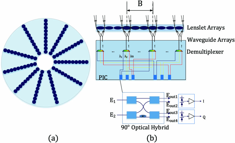
14,15]. The image can be acquired by making an inverse Fourier transform from the mutual coherent intensity, which is detected by the system. A schematic of the detection and tracking system is illustrated in Fig. 1. The top view of the wide-field target detection and tracking system is illustrated in Fig. 1(a), and the principle of the system is illustrated in Fig. 1(b). Light from an extended scene travels through the lenslets and couples into waveguides, and then, the demultiplexer[16,17] divides the light into many spectral channels (e.g., λ1,λ2,,λn). The two demultiplexed lights from each pair of waveguides behind the lenslets meet the coherent condition by path-matching delays. The two lights then couple into a 90° optical hybrid to produce interference[18]. The output of the 90° optical hybrid is as follows: Eout1=E1+E2,Eout2=E1E2,Eout3=E1+jE2,Eout4=E1jE2.

    Schematic of the detection and tracking system. (a) Top view of the system. (b) Working principle of the system.

    Figure 1.Schematic of the detection and tracking system. (a) Top view of the system. (b) Working principle of the system.

    The output signals detected by photodetectors[19]I and Q are as follows: I=Eout1Eout1*Eout2Eout2*=4E1E2cos(Δφ),Q=Eout3Eout3*Eout4Eout4*=4E1E2sin(Δφ),where E1 and E2 are the input signal. Δφ is the phase difference of input signals E1 and E2. With the information collected by the photodetectors I and Q, the image mutual coherent intensity J can be obtained. Finally, the target image is obtained by making an inverse Fourier transform[20].

    According to the Van Cittert–Zernike theorem, the mutual coherent intensity J of paired lenslet (x1,y1) and lenslet (x2,y2) is[15]J(x1,y1;x2,y2)=exp(jφ)(λz)2I(α,β)exp[j2πλz(Δxα+Δyβ)]dαdβ,where λ is the wavelength, z is the object distance, I(α,β) is the light intensity of object, and (Δx,Δy) is the vector distance of paired lenslets, which is also called baseline B. The phase factor φ is given by φ=πλz[(x22+y22)(x12+y12)].

    The spatial frequency of the image is given by (u,v)=1λz(Δx,Δy).

    From Eq. (5), the spatial frequency is proportional to the vector distance of the paired apertures and wavelength. A range of spatial frequencies can be detected by the different baselines assembled by the paired lenslets and demultiplexed working wavelengths.

    From Eq. (5), the highest frequency of the target detection and tracking system is determined by the longest baseline Bmax and the wavelength λ, thus, the resolution of the system can be given by θmin=λBmax.

    When the wavelength is given, the imaging resolution can be determined by the longest baseline, which is the longest distance of the paired lenslets.

    The light from one lenslet is coupled into a waveguide, where the coupling efficiency can be given by[21]ρ(α)=8e3.923(|α|λ/D)2×[er2I0(2.802|α|λ/Dr)J1(πr1.402)dr]2,where α is the angular position of the point source relative to the optical axis, I0 is the zeroth-order modified Bessel function, J1 is the first-order Bessel function, r is the radial distance from any point on the plane of the waveguide to the center of the waveguide, and D is the lenslet diameter.

    From Eq. (7), the efficiency is ten times smaller than that of the on-axis for a non-obstructed circular lens. The FOV of one lenslet coupled into one waveguide can be described by FOVsingle=2|αmax|=2λD.

    If the FOV needs to be expanded, N×N arrays of waveguides can be used, and the FOV can then be given by FOV=N×FOVsingle=2NλD.

    When the diameter and working wavelength of the lenslet are given, the available system FOV can be determined by the waveguide array size.

    According to the previous analysis, the imaging resolution can be determined by the longest baseline and working wavelength, and the available FOV can be determined by the lenslet diameter, waveguide array size, and working wavelength. Different combinations of the working lenslet arrays and working waveguides correspond to different imaging resolutions and FOVs. Thus, we can obtain two operating modes: a detection mode with a wide field and low resolution and a tracking mode with a narrow field and high resolution.

    Detection mode with wide field and low resolution: the side view of the lenslets and waveguide arrays of a single interferometer for the detection mode is illustrated in Fig. 2(a). Paired lenslets with relatively short baselines [the colored lenslets in Fig. 2(a)] operate with all of the corresponding waveguide arrays (WS1, WS2). The paired lenslets with relatively long baselines and the corresponding waveguide arrays (WL1, WL2) do not function. From Eq. (9), all of the working waveguides can achieve a wide FOV. The longest working baseline is determined by the resolution required by the detection mode. From Eqs. (5) and (6), when only paired lenslets with relatively short baselines are working, the range of the relatively low spatial frequencies of the target scene in the wide FOV can be detected; therefore, in the detection mode, resolution of the targets is relatively low, but the FOV of the target scene detected is wide.

    Schematic of system operating modes. (a) Detection mode with wide field and low resolution. (b) Tracking mode with narrow field and high resolution.

    Figure 2.Schematic of system operating modes. (a) Detection mode with wide field and low resolution. (b) Tracking mode with narrow field and high resolution.

    Tracking mode with narrow field and high resolution: the side view of the lenslets and waveguide arrays of a single interferometer for the tracking mode is illustrated in Fig. 2(b). Paired lenslets with all of the baselines [the colored paired lenslets in Fig. 2(b)] and specific waveguides [colored area in WS1, WS2, WL1, and WL2 in Fig. 2(b)] will function. We define the targets we want to monitor as the focus targets. The specific working waveguides can achieve a narrow FOV, which are determined by the position and size of the focus targets imaged in the detection mode. The longest working baseline is determined by the resolution required by the tracking mode. From Eqs. (5) and (6), paired lenslets with all of the baselines [the colored paired lenslets in Fig. 2(b)] operate at all of the spatial frequencies in the range of the available detected frequencies of the targets that can be obtained. Therefore, the resolution of the focus targets is relatively high.

    When using this system to detect and track targets, firstly, the system switches to the detection mode and obtains a wide field with relatively low-resolution imaging. When the focus targets are found from the detection mode results, the system can evaluate the size and position of the focus targets and change the working electronic switches. Then, the system switches to the tracking mode with specific working waveguides, obtains high-resolution images of the focus targets, and predicts the moving path of the focus targets to track them. When the focus targets disappear in the narrow field of the tracking mode, the system switches to the detection mode again to find other new focus targets. The detection and tracking system working flowchart is outlined in Fig. 3. As shown in the example in Fig. 4, with multiple imaging in the tracking mode, the target path can be predicted. The target path in the shape of an arrow can be obtained.

    Flowchart of the detection and tracking system.

    Figure 3.Flowchart of the detection and tracking system.

    Schematic of the working waveguides for tracking focus targets.

    Figure 4.Schematic of the working waveguides for tracking focus targets.

    To verify the feasibility of the system, an example simulated by MATLAB is presented below. The simulation process is as follows: (1) perform a pristine target scene to obtain the intensity; (2) get the light-field distribution at the lenslets plane; (3) perform interference intensity of two beams of light transmitted by waveguides at the output of 90° optical hybrids; (4) obtain the outputs I, Q of the photodetectors; (5) calculate the coherent intensity J corresponding to multiple (u-v) spatial frequencies of all baselines and wavelengths; (6) restore the image by inverse Fourier transform.

    The required performance parameters of the system are listed in Table 1.

    Performance ParametersValue
    Object distance250 km
    Wavelength500–900 nm
    Number of spectral bins10
    Wide-field resolution10 arcsec
    Focus targets resolution2 arcsec
    FOV of wide field10°
    FOV of focus targets0.2° and 0.3°

    Table 1. Target Detection and Tracking System Imaging Performance

    According to the solution to Eq. (6), to achieve the wide-field resolution of 10 arcsec, the corresponding longest baseline in the detection mode should be Bdmax=0.014m. In contrast, to achieve the resolution of the focus targets of 2 arcsec, the corresponding longest baseline in the tracking mode should be Btmax=0.072m.

    Considering the processing difficulty of the lenslets and the aim to collect more light from the targets, the waveguide arrays are chosen to enlarge the FOV. According to Eq. (9), if we assume the system uses 100×100 rectangular arrays of waveguides, which can be accommodated by standard lithographic fabrication techniques[11,22], and the FOV of the single waveguide is 0.1°, the diameter of the lenslets should be about 0.802 mm. For the wide field with an FOV of 10°, the detection mode requires all of the 100×100 rectangular waveguide arrays to be functioning. To achieve FOVs of the focus targets of 0.2°and 0.3°, the tracking mode should use 2×2 or 3×3 rectangular waveguide array, respectively, and the working waveguides can be determined by the positions of the focus targets.

    According to the initial structure of SPIDER, the system uses 37 interferometric arms, and, to sample more spatial frequency, the maximum number of baselines is chosen. The lenslets are arranged next to each other in one interferometric arm[7]. As shown in Fig. 2, the lenslet uses a head-to-tail matching pairing method. According to the relationship between the longest baseline and lenslet diameter, the number of baselines in the detection mode is Ndetection(Bdmax+D)/2D=9, so baseline number 9 is adopted to achieve 3330 frequency samplings according to Eq. (5). The number of baselines in the tracking mode is Ntracking(Btmax+D)/2D=45, so baseline number 45 is adopted to achieve 16650 frequency samplings according to Eq. (5).

    The design structural parameters of the system are listed in Table 2.

    Structure ParametersValue
    Bdmax for detection mode0.014 m
    Btmax for tracking mode0.072 m
    Waveguide arrays for detection mode100×100
    Waveguide arrays for tracking mode2×2 and 3×3
    Lenslet diameter0.802 mm
    Interferometer arms37
    Baselines in single interferometer arm45

    Table 2. Target Detection and Tracking System Structure

    Because of the difficulty in simulating such a large image corresponding to an FOV of 10°, we choose to simulate a relatively small image corresponding to an FOV of 1°, which does not affect the system principle verification. The waveguide array is 10×10. The simulation results of the detection of airplanes in an airport are presented in Fig. 5. Figure 5(a) shows the original input image. The imaging result with an FOV of 1° and imaging resolution of 10 arcsec achieved by the detection mode with short baselines, and all of the corresponding working waveguide arrays are presented in Fig. 5(b). In addition, the outline of the airplanes can be observed without knowing the details. Figures 5(c)5(e) show the focus targets, which are the airplane imaging results of the tracking mode with all of the short and long baselines and corresponding specific waveguides of the working arrays. From the 0.2° and 0.3° FOVs and 2 arcsec resolution imaging, the airplanes are clearer and can be observed in greater detail.

    Simulation results for target detection and tracking system. (a) Pristine target scene used for the simulation; (b) detection mode simulation result; (c)–(e) tracking mode simulation results.

    Figure 5.Simulation results for target detection and tracking system. (a) Pristine target scene used for the simulation; (b) detection mode simulation result; (c)–(e) tracking mode simulation results.

    The peak signal-to-noise ratio (PSNR) is an objective standard for evaluating the imaging quality[23]. The PSNR method is chosen to compare the imaging results with the original image, and the PSNRs are listed in Table 3.

    Comparison FiguresPSNR
    Fig. 5(b) with Fig. 5(a)29.2622
    Fig. 5(c) with Fig. 5(a)38.9698
    Fig. 5(d) with Fig. 5(a)39.1527
    Fig. 5(e) with Fig. 5(a)36.9610

    Table 3. PSNRs of Imaging Result with Original Image

    We can verify the image quality of the two operation modes from the results of Table 3. The narrow-field and high-resolution operating mode image quality is better than that of the wide-field target detection.

    In summary, the simulation result indicates that the detection and tracking system can realize detection of the targets from a wide area and track multiple targets simultaneously without any moving parts.

    In contrast, compared to all of the baselines and waveguide arrays working to realize multiple target high-resolution imaging in a wide field, the target detection and tracking system can reduce the system power consumption, which is achieved through two operating modes via system integration control. The simulation results indicate that the power of the detection mode is 20% of all of the baselines and waveguide arrays, and the power of the tracking mode with three airplanes and synchronous tracking in the FOV is 0.17% of all of the baselines and working waveguide arrays. In addition, the detection and tracking system can reduce the amount of data processing to improve the processing speed and achieve real-time target detection and tracking.

    In this Letter, we present a target detection and tracking system using SPIDER. The system principle is introduced and includes two operating modes: a detection mode and a tracking mode. The system searches the targets from a wide field in the detection mode, and, once the focus targets are found, the system switches to the tracking mode and images the focus targets with a high resolution. We provided a simulation example of the system and used the quality evaluation method PSNR to analyze the simulation results. The results indicate that this system can achieve wide-field target detection and multi-target tracking simultaneously with a high imaging resolution via the integrated system control without any moving parts.

    In conclusion, this system provides a design reference for the application of the new space-based imaging system with simultaneous multi-target detection and tracking in a wide field. As research reports show that the SPIDER technology is still in its infancy, SPIDER imaging system development includes micro–nano manufacturing technology, PICs, spatial frequency domain undersampling image inversion, and other technologies. With the development of SPIDER, the design of the detection and tracking system will be widely applied.

    References

    [1] S. Meimon, J. Jarosz, C. Petit, E. G. Salas, K. Grieve, J.-M. Conan, B. Emica, M. Paques, K. Irsch. Appl. Opt., 56, D66(2017).

    [2] G. Li, L. Li, H. Shen, Y. He, J. Huang, S. Mao, Y. Wang. Appl. Opt., 52, 7919(2013).

    [3] T. Manzur, J. Zeller, S. Serati. Appl. Opt., 51, 4976(2012).

    [4] I. Cohen, G. Medioni. Proceedings of the CVPR ‘98 Workshop on Interpretation of Visual Motion(1998).

    [5] Y. Gao, X. L. Zhang. Proceedings of the 2010 5th IEEE International Conference on Intelligent Systems, 402(2010).

    [6] V. Reilly, H. Idrees, M. Shah. Proceedings of the ECCV 2010, 186(2010).

    [7] R. Bodor, R. Morlok, N. Papanikolopoulos. Proceedings of the 2004 IEEE/RSJ International Conference on Intelligent Robots and Systems, 643(2004).

    [8] R. Kendrick, A. Duncan, J. Wilm, S. T. Thurman, D. M. Stubbs, C. Ogden. Proceedings of the Advanced Maui Optical and Space Surveillance Technologies Conference(2013).

    [9] R. Kendrick, S. T. Thurman, A. Duncan, J. Wilm, C. Ogden. Imaging and Applied Optics, OSA Technical Digest, CM4C.1(2013).

    [10] A. Duncan, R. Kendrick, S. Thurman, D. Wuchenich, R. P. Scott, S. J. B. Yoo, T. Su, R. Yu, C. Ogden, R. Proiett. Proceedings of the Advanced Maui Optical and Space Surveillance Technologies Conference(2015).

    [11] T. Su, R. P. Scott, C. Ogden, S. T. Thurman, R. L. Kendrick, A. Duncan, R. Yu, S. J. B. Yoo. Opt. Express, 25, 12653(2017).

    [12] M. Li, C. L. Zou, G. C. Guo, X. F. Ren. Chin. Opt. Lett., 15, 092701(2017).

    [13] A. Duncan, C. Ogden, D. Wuchenich, R. L. Kendrick, S. T. Thurman. Frontiers in Optics 2015, OSA Technical Digest, FM3E.3(2015).

    [14] M. Francon, S. S. Ballard. Encyclopedia of Physical Science and Technology, 371(2003).

    [15] J. W. Goodman, L. M. Narducci. Phys. Today, 39, 126(1986).

    [16] Z. M. Wang, K. Su, B. Feng, T. H. Zhang, W. Q. Huang, W. C. Cai, W. Xiao, H. F. Liu, J. J. Liu. Chin. Opt. Lett., 16, 011301(2018).

    [17] C. S. Li, X. Y. Qiu, X. Li. Photon. Res., 5, 97(2017).

    [18] T. Hong, W. Yang, H. Yi, X. Wang, Y. Li, Z. Wang, Z. Zhou. Proc. SPIE, 8255, 82551Z(2012).

    [19] P. Zhao, Y. B. Yuan, Y. Zhang, W. P. Qian. Chin. Opt. Lett., 14, 042801(2016).

    [20] A. L. Duncan, R. L. Kendrick. Segmented planar imaging detector for electro-optic reconnaissance. U.S. patent(2014).

    [21] O. Guyon. Astron. Astrophys., 387, 366(2002).

    [22] K. Badham, R. L. Kendrick, D. Wuchenich, C. Ogden, G. Chriqui, A. Duncan, S. T. Thurman, S. J. B. Yoo, T. Su, W. Lai. Conference on Lasers and Electro-Optics Pacific Rim, 1(2017).

    [23] A. Hore, D. Ziou. Proceedings of 2010 20th International Conference on Pattern Recognition, 2366(2010).

    Qinghua Yu, Dongmei Wu, Fuchun Chen, Shengli Sun. Design of a wide-field target detection and tracking system using the segmented planar imaging detector for electro-optical reconnaissance[J]. Chinese Optics Letters, 2018, 16(7): 071101
    Download Citation