1Institute of Lightwave Technology, Beijing Jiaotong University, Beijing 100044, China
2Key Laboratory of All Optical Network and Advanced Telecommunication Network of Ministry of Education, Beijing Jiaotong University, Beijing 100044, China
In a D-shaped twin-core fiber (DTCF), the central core is insensitive to the variation of the external environment, while the other core is highly sensitive. As an electro-optic polymer coated on a DTCF, the coupling between the two cores varies with voltages applied to the polymer. Based on this, a superior all-fiber modulator is proposed that bears little coupling loss, prohibits mode mismatch, and provides a more stable working circumstance. A half-wave driving voltage () of 1.26 V is achieved. Moreover, a high modulation depth of 40 dB can be realized for a voltage of 2.7 V at a 1550 nm wavelength.
Optical modulators are important devices because of their popular applications in telecommunication, laser engineering, and electro-optic (EO) systems. Hence, many forms of optical modulators have been developed, which are mainly modulators based on , GaAs, and EO polymers. Among those modulators, EO polymer modulators have demonstrated exceptional performance for an ultrahigh bandwidth and a subvolt of [1]. Furthermore, EO polymer-based optical modulators offer several advantages over the mature modulators due to the exclusive properties of polymer materials[2]. For the advantages of polymer materials, EO polymer modulators have shown great potential for a variety of applications, such as analog-to-digital conversion[3], a phased-array radar[4], electromagnetic field sensing[5], etc. However, a high propagation loss of about 2 dB/cm is observed in EO polymer waveguides, which hinders its further development and application[6]. Besides, almost all modulators are based on the Mach–Zehnder (MZ) structure, composed of planer waveguides, and deposited on semi-conductor substrates, which result in large coupling losses to optical fibers and velocity mismatch with propagation modes. Thus, the performance of the modulator would be limited. Nowadays, modulators based silicon fibers have shown up. An optical microfiber phase modulator has been proposed with a simple structure, potential compact size, and low-power-driven light, as in Ref. [7]. Also, all-optical modulators based on a graphene microfiber[8] and a graphene-coated fiber[9] have been demonstrated with ultralow loss and high modulation efficiency. Besides, an optical intensity modulator based on a silicon core fiber has been realized with a modulation depth of 10 dB[10]. This not only makes it possible to integrate such silicon-based fiber devices within existing fiber networks, but also has the potential for manipulating the waveguide properties of the devices in ways not possible on-chip. However, the devices, mentioned above, are expensive and complicated for fabrication.
Twin-core fibers (TCFs) are waveguides that have two parallel cores in one fiber. When properly designed and fabricated, a TCF acts as a directional coupling device where periodic optical power transfers between the two cores. Many devices based on TCF have been demonstrated, such as directional couplers[11], optical switching[12], sensors[13], etc. Moreover, an all-fiber low-loss connector for a TCF has been demonstrated with a super low coupling loss of 0.056 dB[14]. Thus, TCFs match well with single-mode fibers (SMFs). A D-shaped fiber has an asymmetrical structure, which is formed by polishing one side of the fiber. When close to the side-polishing surface, the core would be sensitive to the external environment[15]. In fact, a D-shaped TCF (DTCF) is based on an asymmetrical TCF, which is composed of a central and a side core. A DTCF can be obtained by chemical etching, physical grinding, or laser irradiation damage. In a DTCF, the central core is located away from the outside, which makes it stable. Meanwhile, the side core is sensitive to the external environment because it is close to the surface.
In this Letter, we present an all-fiber intensity EO modulator based on a DTCF, which is marked by a simple structure, super stability, and low loss. An EO polymer is coated on the surface of the DTCF. Due to that, the side core is sensitive to the change of the external refractive index (RI), whereas that of the central core is insensitive; the effective RI () of the side core will be numerous if a voltage () is applied to the polymer. The output optical power can be modulated by adjusting the applied voltages. The light totally propagates along the fiber, which exhibits little mismatch with the mode in the splicing SMFs. The TCF-based structure provides a one-arm modulation operation, which is more stable than two-arm MZ modulators. Moreover, this all-fiber device owns distinguished properties for a low cost, low loss, and the possibility of eliminating the semi-conductor substrates.
Sign up for Chinese Optics Letters TOC. Get the latest issue of Chinese Optics Letters delivered right to you!Sign up now
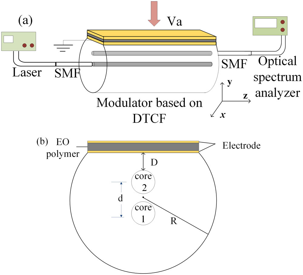
The schematic of the DTCF coupler is illustrated in Fig. 1(a). The coupling is realized by splicing two SMFs to the ends of a piece of DTCF. A laser is employed as the signal source and spliced to the input core by an SMF. An optical spectrum analyzer (OSA) is connected to the output port and applied to measure the transmission spectra. The cross-section of the DTCF is shown in Fig. 1(b). When the DTCF is obtained, the bottom electrode is spun on the surface of the DTCF. The EO polymer and top electrode are located in turns. and denote the radius and RI of the cladding, respectively. The two cores have identical RI profiles, noted as . The radius of the central core (core 1) and the side core (core 2) are measured as and , respectively. Besides, and represent the central distance between the two cores and the length of the DTCF. , , , and denote the etching depth, thickness of the EO polymer, thickness of the two electrodes, and RI of the EO polymer, respectively. In the DTCF, to improve the sensitivity of core 2, the values of and are set to be close to .
Figure 1.(a) Schematic of the DTCF coupler. (b) The cross-section of the DTCF.
According to the weak coupled-mode theory, the output fundamental mode of the TCF is excited with the power of[16]where, is the propagation constant for the fundamental mode of core 1 and core 2, respectively. The mode-coupling coefficient is a measure of the spatial overlapping of the mode fields of core and over the cross-section area of core . The light propagates along the axis.
According to Eq. (1), the interference signal reaches its maximum when satisfies the condition of When , the first order of the total coupling length can be defined as
In the DTCF, core 2 is located close to the external surface, which makes it susceptible to the variation of the RI or thickness of the polymer. However, the performance of core 1 stays static. Thus, when the external environment changes, the propagation constant for the fundamental mode of the two cores will be different, which results in the power from core 1 coupled into core 2 changing. Therefore, the output intensity could be modulated by adjusting the applied voltage. Poly (methyl methacrylate) (PMMA) has been used in many technological fields due to its excellent optical transparency, light weight, and good mechanical properties[17]. In this Letter, PMMA is applied as the polymer. The coefficient of the polymer is set to be 300 pm/V[18]. For the TM mode, the RI of EO polymer can be expressed by[19]For a better acknowledgment of the modulator, only a TM mode is applied at the input port. Hence, only the TM mode operation is analyzed.
To investigate the different performances of the two cores, and are defined as the shift of and within a range of voltages of , respectively. Figure 2 illustrates as a function of the etching depth, the thickness of the electrodes, and the thickness of the polymer at , where , , at a 1550 nm wavelength, , , and , respectively. A dramatic small shift of is observed, which varies in the range of . It reveals that core 1 is hardly affected by the external environment. Therefore, we mainly focus on analyzing the properties of core 2.
Figure 2. versus (a) the etching depth, (b) the thickness of the electrodes, and (c) the thickness of the EO polymer.
Accounting for the D-shaped fiber, closer to the edge, the core will be more sensitive to the external medium but with a higher loss. Figure 3 shows and the propagation loss of core 2, corresponding to the etching depth. The thickness of the electrodes and polymer are 1.5 nm and 5 μm, respectively. From Fig. 3, is reduced with the increment of the etching depth. At , values of and are obtained with and , respectively, for . As to the propagation loss, 0.37–0.39 dB/cm is obtained in the voltage range of 0 to 10 V at . After all, the etching depth is assumed to be 20 nm.
Figure 3. versus the etching depth at and (black). Propagation loss versus the etching depth at , , and (red).
The bottom electrode is located on the surface of the DTCF, which is made of gold. Figure 4 illustrates and the propagation loss as a function of the thickness of the electrodes. Values of and are obtained with and , respectively, for . However, because of the large imaginary part of the RI, a large propagation loss would be exhibited. At , the loss of 1 dB/cm is obtained, and the loss rises up as high as 5 dB/cm for the electrode thickness of 10 nm. Considering both and the propagation loss, the thickness of the electrode is assumed to be 2 nm.
Figure 4. versus the thickness of the electrodes at and (black). Propagation loss versus the thickness of the electrodes at , , and (red).
As it is known, a larger thickness of the polymer leads to a more significant effect on core 2, but a small for a certain voltage from Eq. (5). Figure 5 depicts and the propagation loss as a function of the thickness of the polymer. increases in the range of , and then reduces for a further increment of the thickness of the polymer. However, the propagation loss decreases with the growing thickness of the polymer. At , a loss of 0.47 dB/cm is obtained. Thus, the thickness of the polymer is fixed to 5.5 μm.
Figure 5. versus the thickness of the polymer at and (black). Propagation loss versus the thickness of the polymer at , , and (red).
On account of the high sensitivity of core 2, the etching depth, the thicknesses of the electrodes, and the polymer are set to be 20 nm, 2 nm, and 5.5 μm, respectively. The length of the DTCF is assumed to be the first order coupling length . Figure 6 illustrates the normalized output optical power as a function of the applied voltages at the coupling length of 1.36 cm. The output power ranges from 0 to 0.025, which is overwhelmingly invisible. It is because of that, a poor coupling between the two cores exists in this condition.
Figure 6.Normalized optical power versus the applied voltages at .
For a superior modulation mechanism, the modulator should be designed to meet the total coupling condition without the applied voltages. The complete coupling could be achieved by adjusting the radius of core 1, while the RI of the two cores remains identical. Figure 7 illustrates and as functions of the radius of core 1 at . From Fig. 7, increases corresponding to a growing radius. With the rising , there is a point (A), where . Thus, the total coupling can be achieved at .
Figure 8 illustrates the optical intensity as a function of the applied voltages. The coupling length of the DTCF is 1.54 cm. Complete coupling occurs without the applied voltages. The power reduces with voltages in the range of 0 to 8 V, and then the power goes up when . This is because the difference of the coupling coefficients between the two cores varies nonlinearly, while the difference of the propagation constant relates linearly to the voltages. Thus, a rising output intensity is exhibited. As Fig. 8 illustrates, the half-wave driving voltage is 3.78 V.
Figure 8.Normalized optical power versus the applied voltages at .
In fact, a half-wave driving voltage of 3.78 V is quite large for modulators. The RI variation of the EO polymer has a more significant effect on core 2 for smaller core sizes. Consequently, for a certain , the sensitivity of core 2 with a smaller size will be improved. Thus, could be lower by minimizing the radius of core 2. For a better confinement to the light, the RI of the two cores should be enlarged. Once core 2 is minimized, the coupling length and radius of core 1 would be adjusted. However, the decreasing radius would bring larger propagation loss. The properties of the DTCF in the simulation are shown in Table. 1. Figure 9 illustrates the normalized intensity as a function of the applied voltages for a different radius of core 2. The half-wave voltages decrease with the decreasing . At , the half-wave voltage is 1.26 V. Moreover, can be lowered by applying materials with a higher EO coefficient or by narrowing the difference of RI between the EO polymer and the fiber core by a further step. Figure 10 illustrates the transmission spectrum of the modulator versus the applied voltages of 0, 1.26, 2.5, 2.65, and 2.7 V with . A half-wave modulation of 3 dB is realized at the voltage of 1.26 V, which agrees with the results in Fig. 9. The modulation depths of 20 and 30 dB are obtained with a voltage of 2.5 and 2.65 V, respectively. Besides, it reaches a superior modulation depth of 40 dB for a voltage of 2.7 V at the wavelength of 1550 nm.
Figure 9.Normalized optical power versus applied voltages at , , , and .
In conclusion, we introduce the concept of a coated DTCF and show the modulation properties of this architecture, which are composed of an all-fiber structure. It is optimized by the etching depth, the thickness of the electrodes, and the polymer for an excellent modulator, respectively. In this modulator, a half-wave voltage of 1.26 V is realized at the side core radius of 2 μm with a length of 2.64 cm. A modulation depth, as high as 40 dB, can be achieved for a voltage of 2.7 V. Instead of modulation, this structure will have potential applications in imaging, display, holography, metrology, and sensors, which will be investigated later.
[3] S. R. Nuccio, R. Dinu, B. Shamee, D. Parekh, C. Chang-Hasnain, A. Willner. Optical Fiber Communication Conference/National Fiber Optic Engineers Conference 2011, JThA030(2011).